Abstract
The article considers the possibilities of developing the combined discrete-continuous vibratory systems, in which the disturbing member is designed in the form of the uniform elastic rod with distributed inertia and stiffness parameters. The forced oscillations of the continuous member of the three-mass vibratory system are analyzed. Based on the Krylov-Duncan functions (circular and hyperbolic functions), the system of equations describing the motion of the continuous rod is derived. The novelty of the present paper consists in deriving the mathematical model of the discrete-continuous vibratory system, in which the model of the discrete subsystem is combined with the model of the continuous subsystem by applying the reactions in the supports holding the uniform elastic rods. The inertia-stiffness parameters of the vibratory system are determined and the analytical dependencies for calculating the reactions in supports are derived. The frequency-response curves of the considered discrete-continuous vibratory system are constructed. The deflection (bending) diagram of the continuous members is plotted for the case of forced oscillations of the combined discrete-continuous vibratory system.
Highlights
- The possibilities of designing the disturbing members of the three-mass vibratory systems in the form of the uniform elastic rods with distributed inertia and stiffness parameters are considered.
- The mathematical model describing forced oscillations of the three-mass discrete-continuous vibratory system is derived, and the equations of deflections of the continuous member are deduced using the Krylov-Duncan functions.
- The frequency-response curves (or, so-called, amplitude-frequency characteristics) of the three-mass vibratory system are plotted, and the corresponding deflection (bending) diagram of the continuous member is constructed.
1. Introduction
The major characteristics of any vibratory machine depend on the structure of its oscillatory system and vibration exciter. Most of the existent industrial vibratory machines are equipped by single-mass or double-mass oscillatory systems, and by inertial, electromagnetic or crank-type vibration exciters. The paper [1] is dedicated to dynamics and stability investigation of a single-mass vibratory system with inertial vibration exciter. In the paper [2], the authors studied the dynamic behavior of a double-mass vibratory machine with inertial vibration exciter. The problems of synthesizing three-mass resonance vibratory systems with electromagnetic drive are considered in [3]. The papers [4-6] are aimed at the investigation of the single-mass and double-mass oscillatory systems with crank excitation mechanisms. In all the previously mentioned papers, the oscillatory system is considered as a discrete one, i.e., each vibrating mass is modelled as a solid (nondeformable) body.
In the paper [7], there are discussed the possibilities of synthesizing the oscillatory systems with continuous members, and the problems of modelling the dynamic behavior of an elastic rod considered as a disturbing body. Different theoretical techniques of studying free vibrations of a cantilever beam with several spans are considered in [8]. Despite the fact that numerous scientific publications are dedicated to discrete-continuous oscillatory systems, the problems of synthesizing the three-mass structures with rod-shaped elastic members excited by crank mechanisms are not thoroughly investigated. In the previous publications of the authors, there were considered the technique of calculation of the inertia-stiffness parameters of the three-mass discrete oscillatory system ensuring its operation in energy-efficient resonance mode [9], and the forced and free oscillations of an elastic rod considered as a disturbing body of the three-mass discrete-continuous oscillatory system [10, 11]. The novelty of the present paper consists in deriving the mathematical model of the discrete-continuous vibratory system, in which the model of the discrete subsystem is combined with the model of the continuous subsystem by applying the reactions in the supports holding the uniform elastic rod.
2. Calculation diagram and mathematical model of discrete-continuous inter-resonance oscillatory system
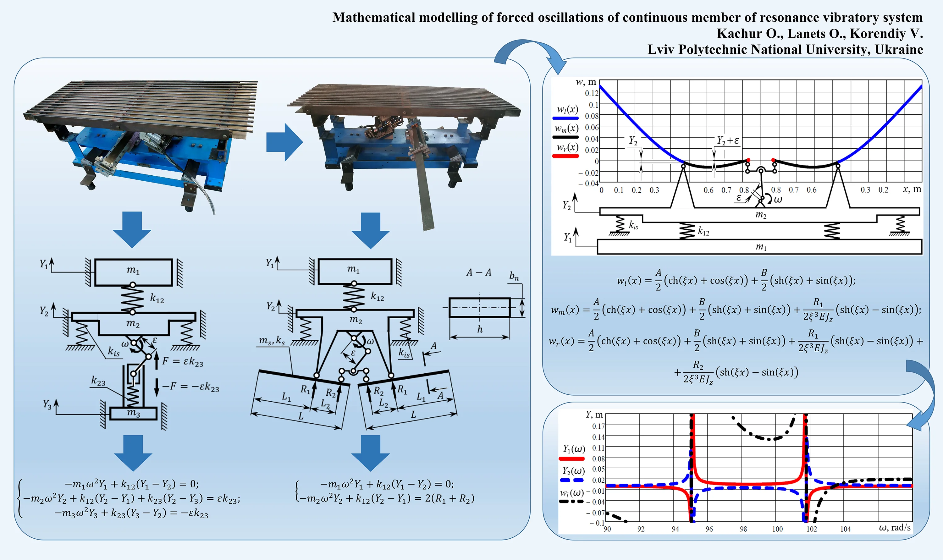
In Fig. 1(a), there is presented the three-mass discrete vibratory system whose bodies performs straight-line (linear) oscillations [10]. It consists of the active mass connected to the intermediate mass with the help of the spring unit of stiffness . The vibration excitation of the system is characterized by the forced circular frequency , and is carried out with the help of the crank mechanism whose drive is installed on the intermediate mass . The crank of the exciting mechanism ensures the disturbing eccentricity , and is connected to the spring unit installed on the reactive mass . The intermediate mass of the vibratory system is supported by the vibration isolators of stiffness . The mathematical model of the three-mass discrete oscillatory system can be derived in the amplitude form as follows [10]:
where , , are the amplitude values of displacements of the corresponding masses.
Fig. 1Calculation diagrams of a) three-mass discrete and b) discrete-continuous oscillatory systems
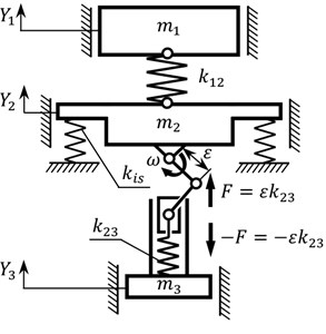
a)
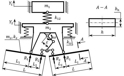
b)
The general condition of increasing the system efficiency consists in the fact that the value of the reactive mass and the stiffness of the corresponding spring unit must be very small in comparison with the other masses and springs. Such features are characteristic of an elastic body, i.e. continuous member, which optimally combines the inertial and stiffness parameters. The basic peculiarity of the oscillatory system presented in Fig. 1(b) consists in the fact that it is constructed of the discrete and the continuous subsystems. The discrete subsystem is formed by the double-mass oscillatory system that consists of the active mass and the intermediate mass , which are connected to one another by the spring unit of the stiffness . The continuous subsystem is formed by two elastic bodies simultaneously combining the distributed stiffness parameters and inertial parameters . The continuous member is considered as an elastic rod connected to the intermediate mass and to the disturbing rod of the crank excitation mechanism by two hinged joints. Due to the rotation of the crank, the rod performs oscillatory motion, and is subjected to the corresponding reactive forces and applied at hinged supports. The cantilever section of the elastic rod ensures the possibility of accumulating the necessary inertial energy for disturbing the intermediate body, as well as the whole oscillatory system. The considered system consists of two continuous members.
To determine the amplitude values of displacements of the active mass and the intermediate mass of the discrete-continuous oscillatory system, let us rewrite Eq. (1) in the following form:
where the expression models the action of two continuous members upon the intermediated mass; , are the reactions in the hinged supports holding the elastic rods. The reactions in the supports can be determined from the system of equations describing the forced oscillations of the continuous member. Such a system can be formed on the basis of the circular and hyperbolic functions (Krylov-Duncan functions) , ,, [11]:
where, are arbitrary constants; is the modulus of elasticity of elongation for the rod material; is the moment of inertia of the rod cross-section about its neutral line; , , are the lengths of the rod sections; ; is the density of the rod material; is the forced circular frequency; , are the width and the thickness of the continuous member.
Solving Eq. (3), let us derive the analytical expressions for the unknowns , , , :
Substituting Eq. (6) and Eq. (7) into Eq. (2), the analytical expressions for the amplitudes and have been derived. They are not presented in the paper because of their large sizes. Nevertheless, the obtained dependencies allow for analyzing the frequency-response curves (or, so-called, amplitude-frequency characteristics) of the discrete-continuous system.
In accordance with the input data [10], the forced circular frequency 99.5 rad/s, the amplitude displacement of the active mass 5∙10-3 m, the inertial parameters 83.7 kg, 62.1 kg, the stiffness of the spring unit 3.794∙105 N/m. In order to ensure the prescribed amplitude of the active mass, and taking into account the following parameters of the continual member [11]: 7850 kg/m3, 0.0225 m, 5.74∙10-3 m, 2.1∙1011 Pa, , 0.475 m, 0.355 m, 0.8301 m, the calculated value of the eccentricity of the crank mechanism is equal to 4.75∙10-3 m. In this case, the amplitude displacement of the intermediate mass is following –5.9∙10-3 m. Substituting the obtained parameters into Eq. (4)-(7), let us determine the values of , , , :
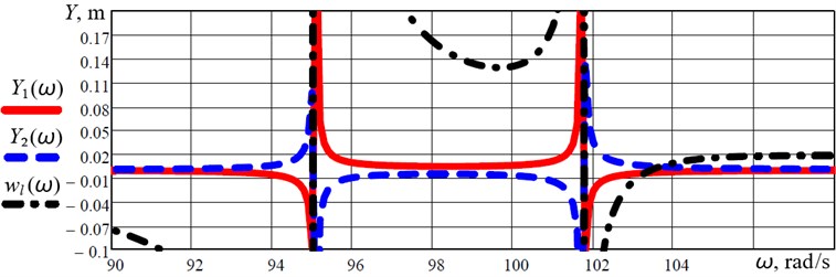
Using the derived analytical expressions for the amplitudes and , let us plot the corresponding frequency-response curves (or, so-called, amplitude-frequency characteristics) of the discrete-continuous system (Fig. 3). Based on the obtained results it can be seen that the first two resonance peaks take place at the frequencies of 95 rad/s and 101.8 rad/s. This fact allows for concluding that the considered discrete-continuous system is working under the inter-resonance conditions characterized by high efficiency. The next stage of the investigations is aimed at analyzing the amplitude of oscillations of the continuous member.
3. Calculation of deflection of the continuous member
Let us analyze the deflections of the separate sections of the elastic rods (continuous members). Let us denote the deflection of the left section ( [0…0.475 m]) as , of the middle section ( [0.475 m…0.83 m]) as , and of the right section ( [0.83 m…0.8301 m]) as (Fig. 2). The corresponding deflections can be described by the following equations:
Substituting the above calculated values of the constants , , and the reactions , (see Eq. (9)) into Eq. (10), let us plot the corresponding deflection diagram (Fig. 2).
Fig. 2The diagram of deflections of the continuous members during their forced oscillations
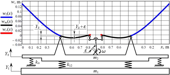
Analyzing the diagram of Fig. 2, it can be concluded that the maximal deflection of the continuous member takes place on its cantilever section: the amplitude displacement of the rod’s free end is equal to 0.129 m. The displacement of the left hinged support is equal to the displacement of the intermediate mass –5.9∙10-3 m, and the displacement of the right hinged support is equal to –5.9∙10-3 + 4.75∙10-3 = –1.15∙10-3 m.
Using Eq. (10) for analyzing the deflection of the free end of the continuous member, and taking into account the value of eccentricity of the crank mechanism, which ensures the amplitude of oscillations of the active mass equal to 5 mm at the forced frequency of 99.5 rad/s, let us plot the frequency-response curves of the discrete-continuous system taking into account the deflection of the continuous members (Fig. 3).
Fig. 3Frequency-response curves (amplitude-frequency characteristics) of the discrete-continuous system taking into account the deflections of the continuous members
4. Conclusions
The possibilities of development and implementation of the combined discrete-continuous vibratory systems are considered. It is proposed to design the disturbing member in the form of the uniform elastic rod with distributed inertia and stiffness parameters (Fig. 1). The mathematical model describing forced oscillations of the three-mass discrete-continuous vibratory system is derived, and the equations of deflections of the continuous member are deduced using the Krylov-Duncan functions. In the proposed calculation diagram, the model of the discrete subsystem is combined with the model of the continuous subsystem by applying the reactions in the supports holding the uniform elastic rods. Based on the prescribed inertia-stiffness parameters of the vibratory system, the analytical dependencies for calculating the reactions in supports are derived.
Using the proposed mathematical model describing the forced oscillations of the three-mass discrete-continuous system, the corresponding frequency-response curves (or, so-called, amplitude-frequency characteristics) are plotted (Fig. 3). The first two resonance peaks take place at the frequencies of 95 rad/s and 101.8 rad/s. This means that the system is working under the inter-resonance conditions characterized by high efficiency. The amplitude displacement of the active mass is equal to 5 mm at the forced frequency of 99.5 rad/s.
Based on the derived equation for analyzing the deflection of the free end of the continuous member, the corresponding deflection (bending) diagram is plotted (Fig. 2). The maximal displacement of the rod’s free end is equal to 0.129 m, of the left hinged support – 5.9∙10-3 , and of the right hinged support – 1.15∙10-3 m. The prospects of further investigations on the subject of the paper include the analysis of the damping effect on the system oscillations, and the experimental testing of forced oscillations of the discrete-continuous system.
References
-
Yatsun V., Filimonikhin G., Haleeva A., Nevdakha A. On stability of the dual-frequency motion modes of a single-mass vibratory machine with a vibration exciter in the form of a passive auto-balancer. Eastern-European Journal of Enterprise Technologies, Vol. 4, Issue 7(92), 2018, p. 59-67.
-
Filimonikhin G., Yatsun V., Kyrychenko A., Hrechka A., Shcherbyna K. Synthesizing a resonance anti-phase two-mass vibratory machine whose operation is based on the Sommerfeld effect. Eastern-European Journal of Enterprise Technologies, Vol. 6, Issue 7(108), 2020, p. 42-50.
-
Gursky V., Kuzio I., Korendiy V. Optimal synthesis and implementation of resonant vibratory systems. Universal Journal of Mechanical Engineering, Vol. 6, Issue 2, 2018, p. 38-46.
-
Alşverişçi G. F. The nonlinear behavior of vibrational conveyers with single-mass crank-and-rod exciters. Mathematical Problems in Engineering, Vol. 2012, 2012, p. 534189.
-
Igumnov A. L., Metrikin S. V., Nikiforova V. I. The dynamics of eccentric vibration mechanism (Part 1). Journal of Vibroengineering, Vol. 19, Issue 7, 2017, p. 4854-4865.
-
Igumnov A. L., Metrikin S. V., Nikiforova V. I., Fevral’skikh L. N. The dynamics of eccentric vibration mechanism (Part 2). Advanced Structured Materials, Vol. 137, 2021, p. 173-190.
-
Gursky V., Kuzio I. Dynamic analysis of a rod vibro-impact system with intermediate supports. Acta Mechanica et Automatica, Vol. 12, Issue 2, 2018, p. 127-134.
-
Jaworski J. W., Dowell E. H. Free vibration of a cantilevered beam with multiple steps: comparison of several theoretical methods with experiment. Journal of Sound and Vibration, Vol. 312, Issues 4-5, 2008, p. 713-725.
-
Korendiy V.,Lanets O., Kachur O., Dmyterko P., Kachmar R. Determination of inertia-stiffness parameters and motion modelling of three-mass vibratory system with crank excitation mechanism. Vibroengineering Procedia, Vol. 36, 2021, p. 7-12.
-
Lanets O. S., Kachur O. Yu., Korendiy V. М. Classical approach to determining the natural frequency of continual subsystem of three-mass inter-resonant vibratory machine. Ukrainian Journal of Mechanical Engineering and Materials Science, Vol. 5, Issues 3-4, 2019, p. 77-87.
-
Lanets O., Kachur O., Korendiy V., Dmyterko P., Nikipchuk S., Derevenko I. Determination of the first natural frequency of an elastic rod of a discrete-continuous vibratory system. Vibroengineering Procedia, Vol. 37, 2021, p. 7-12.
Cited by
About this article

