Abstract
The dynamics of the gun drilling process is analyzed in this paper. The tool shank is modeled as long straight beam vibrating in transverse direction under action of cutting forces. Axial force component is expressed as proportional to cutting thickness, which is determined as nonlinear function of beam transverse deflection with time delay. Nonlinear equations of motion of the drilling shank are derived. The stability diagram of the system dynamics was determined. The bifurcation analysis of nonlinear differential delay equations by means of multiple scale method was performed. The obtained results were verified by numerical integration of nonlinear equations. The influence of cutting conditions on system stability and chatter amplitude was observed.
1. Introduction
Long straight holes are usually produced by means of a special drilling tool. This efficient process is widely used in the automotive industry to drill deep holes in cylinder heads, crankshafts, fuel pump housings, turbine blades and etc. Gundrilling is the mostly used method of deep small hole machining. Gun drill has asymmetrical single edge tool design with long straight tube of asymmetrical cross-section with a typical reachable diameter range of 0.5 mm up to 40 mm and length-to-diameter- ratios up to / = 400 (in special applications even / = 900 [1]). The method is widely applied in machining small deep holes as it provides a good straightness and high quality of machined surface due to its self-guiding action [2]. Optimal drill performance in gundrilling is achieved when the combination of the cutting speed, feed rate, tool geometry, carbide grade, and coolant parameters are selected properly depending upon the work material, deep-hole tool machine conditions, and the quality requirements to the drilled holes. Due to low flexural stiffness of gun drill shank lateral vibrations of high magnitude could be excited during the machining. Excessive vibrations are detrimental to finish surface quality and may damage the tool. Therefore, it is important to predict in advance regimes with chatter vibrations. The regenerative mechanism is the main source of chatter vibrations. And it requires that time-delayed terms in model equations should be taken into account. The same mechanism emerges not only in drilling [3-5], but in milling [6], boring etc. The comprehensive review of present state of deep hole drilling modeling was given in [1]. Most authors modeled drill shank using the reduced single degree of freedom system. In this paper gun drill is considered as flexible continuous beam loaded with eccentrically applied cutting force. The new approach allows considering the influence of lateral vibrations on the dynamics of the gun drilling system. The multiple scale method is applied for nonlinear vibrations analysis. Stability diagram was constructed and bifurcation diagrams were obtained by multi-scale expansion. The nonlinear behavior of system in vicinity of stability borders was analyzed by using numerical integration of nonlinear equation.
2. Model of gun drilling system
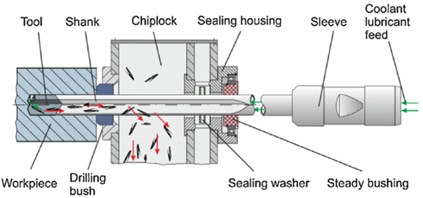
Gun drill shank is modeled as long slender beam using Euler-Bernoulli beam theory. The beam axial line is supposed to be straight line in undeformed state. Schematic of gun drilling process is presented on Fig. 1. Usually gun drill rests upon intermediate supports, but we suppose that clearance in these supports is large enough, so that these supports are not taken into consideration. Therefore, for the sake of simplicity we assume, that gun drilling shank as simply supported beam.
Fig. 1Scheme of gun drilling process.
Gun drill tool has asymmetric cutting edge design, components of cutting force are shown in Fig. 2(a). In-plane component of cutting force () is balanced by guiding pads, while tangential component of force leads to torque loading upon gun drill.
Axial component of cutting force is applied with eccentricity – . Therefore, beam is loaded with axial force and bending moment. The mathematical model is presented in Fig. 2(b).
Fig. 2Loading conditions of gun drill cutting edge and drawing of mathematical model of gun drilling system
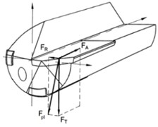
a) Loading conditions of gun drill cutting edge
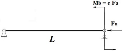
b) Drawing of mathematical model of gun drilling system
Nonlinear partial differential equation of beam vibration in plane of minimal rigidity were derived in [7] as:
where – lateral displacement of beam axis, – time, – axial coordinate, – mass of unit length, – flexural stiffness of the beam, – axial force acting at the beam end, – bending moment, due to cutting force eccentricity, – Dirac function, – length of the beam. Deflection in other plane and torsion are ignored.
Chatter vibrations occur due to regenerative mechanism as the vibrating tool cutting edge interacts with the surface left by edge at its previous pass [8, 9]. To model this phenomenon we assume, that cutting force is proportional to the uncut chip thickness , which is dependent upon axial position of the cutting edge at instant moment and time delayed by period of workpiece rotation :
where – cutting coefficient, – eccentricity of the applied cutting force, – chip thickness, – feed, – delay equal to work piece rotation period, – axial displacement.
Axial displacement of the beam end is expressed nonlinearly through lateral displacement as:
Under such loading transverse vibrations arise and it leads to axial deflection of tool tip and therefore varying uncut chip thickness and forces [10]. Various models of tool vibrations under drilling were analyzed by authors in [8, 11, 12]. Chatter vibrations in these papers are explained due to axial or axial-torsional deformation of tool. However, for gun drill with high length-to-diameter ratio flexural vibrations are more significant and are analyzed in the paper.
The equations of flexural-torsional tool vibration under finite tool shank deflection were analyzed in [9]. It was shown that chatter vibration occurs in vicinity of lower eigenfrequency with eigenmode corresponding to this frequency.
Equations of motion in nondimensional form were obtained [7], following nondimensional variables and parameters were introduced:
Here and after we omit all tildes and use nondimensional variables only.
Next, we discretize system equations by means of Galerkin method using first flexural mode in plane of minimal flexural rigidity. We also add viscous damping to take into account dissipation of energy [7]:
where:
– time-delayed variable value, – damping coefficient.
Further we will study the effect of nonlinear regenerative mechanism for chatter vibrations excitation, thus we simplify equations by neglecting terms corresponding the geometrical nonlinearity of the system, except for terms, which are associated with determining axial displacement and loading containing the delayed functions. This could be done due to the fact, that usually cutting coefficient is much higher compared to other terms and are highly responsible for chatter vibration excitation. The geometrical nonlinearity consideration leads to nonsignificant variation of chatter stability borders.
After such assumptions we get:
Term represents constant component of bending moment, which defines the static deflection . To study dynamic displacement near the equilibrium position, we rewrite equation of motion in vicinity of bent equilibrium state for dynamic component of beam deflection as follows:
where:
The Eq. (8) feature concludes in existence of time delay variables in linear and nonlinear terms, that requires stability analysis and investigation of stationary regimes of linearized equation, and self-vibrations analysis near the border of stability.
3. Numerical analysis
3.1. Stability of linearized equation
First, we perform linear stability analysis via -decomposition technique in domain of system parameters (coordinates ). Linearized Eq. (8) reads as followed:
To find stability boundaries, we express unknown variable in exponential form. After separating real and imaginary term we get system of transcendental equations:
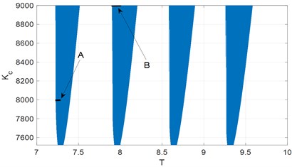
Solving these equations in respect to , for different values of we obtain classical periodically altering regions of stability and instability (Fig. 3). Values of parameters used in this paper are 0.0493, , .
The behavior of the system in vicinity of stability borders is of great interest. Bifurcation analysis of the dynamical system requires analysis of full nonlinear Eq. (8).
Fig. 3Stability diagram of linearized system. A and B – regions where bifurcation analysis is performed
3.2. Nonlinear analysis
To investigate dynamic behavior after stability loss we perform bifurcation analysis of nonlinear differential delay equations by means of multiple scale method [13]. We introduce time, variable and time delay as:
where – critical delay corresponding to stability boundary.
The delayed variable is expanded as:
where , , .
Substituting Eqs. (12)-(15) and equating the same terms of power , the following partial differential equations are obtained:
General solution of first equation is written as:
Quadratic terms do not introduce secular terms in second approximation, therefore , and , are independent of time-scale . However, quadratic terms still contribute to third approximation equations. Second approximation has a form:
where , , – coefficients, which are expressed in terms of , .
After elimination of secular terms in third approximation we get first order differential equations in respect to unknowns , .
It is convenient to introduce solution of equations in polar form:
where , – amplitude and phase.
Eliminating from equations we get differential equation for amplitude . To find limit cycle amplitude we assume, that . As a result we will derive the algebraic equation for limit cycle amplitude calculation. Resulting equation has a form:
Obtained functions and are quite cumbersome and are not presented here. All algebraic manipulations were performed in Matlab Symbolic toolbox.
The system behavior in the vicinity of the bifurcation point has been studied in order to analyze the nature of Andronov-Hopf bifurcation with respect to system parameters variation. Here we vary delay parameter, which corresponds to rotational velocity of gundrill.
Bifurcation diagram for two regions in the vicinity of the stability border. (Fig. 3, regions A, B) have been analyzed by means of asymptotic method. Amplitudes of limit cycle vs parameter T in Fig. 6 are presented. To verify results obtained by asymptotic method we perform numerical time integration of Eq. (8) using implicit scheme with iterations. Examples of resulting displacement time histories and its Fourier spectrum are shown in Figs. 4-5. Amplitudes of steady motion, obtained by numerical integration are compared with the results of asymptotic method. Bifurcation diagrams for two cases determined by two methods in Fig. 6 are presented.
Fig. 4Time history for x and Fourier spectrum of steady motion. Parameters: Kc= 8000, T= 7.2433
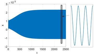
a) Time history for
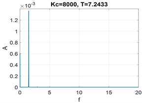
b) Fourier spectrum of steady motion
Fig. 5Time history for x and Fourier spectrum of steady motion. Parameters: Kc= 9000, T= 7.9261
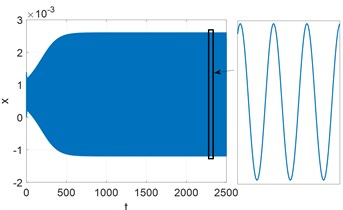
a) Time history for
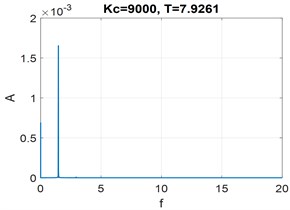
b) Fourier spectrum of steady motion
Results obtained by asymptotic method are found to be in good agreement with results obtained by numerical integration.
Fig. 6Bifurcation diagram determined by asymptotic analysis and numerical integration
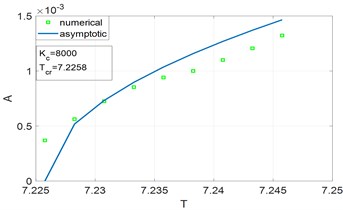
a) Zone A, 8000, 7.2258
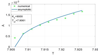
b) Zone B, 9000, 7.9061
4. Conclusions
In this paper nonlinear model of chatter vibrations of gundrilling tool is presented. Stability diagram of the linearized system was obtained. The relative cutting speed is the main critical parameter which effects on process stability. Post-critical behavior after stability loss was analyzed by means of method of multiple scales. The bifurcation diagrams of the dimensionless cutting speed (speed of detail rotation) influence on chatter vibration amplitude were determined. The results of numerical simulation and the nonlinear equation asymptotic solution showed good agreement. Presented model could be used for stability analysis and for prediction of amplitudes of chatter in unstable zone. The results of modeling can be exploited in industry for optimal cutting conditions determination.
References
-
Biermann D., Bleicher F., Heisel, Klocke F., Möhring H. C., Shih A. Deep hole drilling. CIRP Annals, Vol. 67, Issue 2, 2018, p. 673-694.
-
Sakuma K., Taguchi K., Katsuki A., Takeyama H. Self-guiding action of deep-hole-drilling tools. CIRP Annals, Vol. 30, Issue 1, 1981, p. 311-315.
-
Ivanov I. I., Voronov S. A. Processing parameters influence on dynamics of vibratory drilling with adaptive control. MATEC Web of Conferences, Vol. 226, 2018, p. 02001.
-
Kiselev I. A., Zhukov N. A., Selivanov A. N., Barysheva D. V., Voronov S. A., Gouskov A. M. Three-dimensional modeling of deep hole vibratory drilling dynamics. Procedia Engineering, Vol. 176, 2017, p. 50-55.
-
Ivanov I., Pleshcheev I., Larkin A. Investigation of controlled vibratory drilling dynamics with variable velocity feedback gain. International Conference on Industrial Engineering, 2018, p. 585-594.
-
Kuts V., Kiselev I., Voronov S. Vibrations reduction in milling by using singular spectral analysis. MATEC Web of Conferences, Vol. 224, 2018, p. 01102.
-
Voronov S. A., Gouskov A. M., Svetlitsky V. A. Vozbuzhdenie poperechnyh avtokolebanij steblja instrumenta pri glubokom sverlenii (Excitation of lateral self-oscillations of tool shank during deep hole drilling). Raschety na prochnost' (Strength Analysis) Mashinostroenie, 1979, p. 172-182, (in Russian).
-
Batzer S. A., A. M., Gouskov, Voronov S. A. Modeling vibratory drilling dynamics. Transactions ASME. Journal of Vibration and Acoustics, Vol. 123, Issue 4, 2001, p. 435-443.
-
Altintas Y. Manufacturing Automation: Metal Cutting Mechanics, Machine Tool Vibrations, and CNC Design. Cambridge University Press, 2000.
-
Gouskov A. M., Voronov S. A., Butcher E., Sinha S. C. Nonlinear flexural-torsional vibrations of a gundrilling tool. International Design Engineering Technical Conferences and Computers and Information in Engineering Conference, 2005, p. 971-980.
-
Bayly P. V., Metzler S. A., Shaut A. J., Young S. G. Theory of torsional chatter in twist drills: model, stability analysis and composition test. Transactions ASME. Journal of Manufacturing Science and Engineering, Vol. 123, 2002, p. 552-561.
-
Bleicher F., Reiter M., Brier J. Increase of chip removal rate in single-lip deep hole drilling at small diameters by low-frequency vibration support. CIRP Annals, Vol. 68, Issue 1, 2019, p. 93-96.
-
Nayfeh A. H. Perturbation Methods. John Wiley & Sons, 2008.
Cited by
About this article

