Abstract
A continuous rod-shaped member (a body with distributed inertia and rigidity parameters), which is the object of the investigations, is considered. To ensure the optimal natural frequency concerning the oscillations of the reactive (exciting) mass of the three-mass discrete vibratory system, with the use of the Krylov-Duncan functions, the mathematical model describing forced oscillations of the continuous member considered as a disturbing body of the three-mass discrete-continuous vibratory system is established, and the corresponding frequency equation is analytically derived. The obtained theoretical results are verified using the Finite Element Method in SolidWorks software. The novelty of the present paper consists in substantiation of the possibilities of implementing the continuous rod-shaped members with distributed inertia and rigidity parameters for exciting the oscillations of the three-mass discrete-continuous inter-resonance vibratory systems.
Highlights
- The mathematical model describing forced oscillations of the continuous member considered as a disturbing body of the three-mass discrete-continuous vibratory system is established.
- The frequency equation and the analytical expression for calculating the first natural frequency of the continuous member (elastic rod) of the discrete-continuous vibratory system are derived.
- Frequency analysis of a rod-shaped continuous body is performed using Finite Elements Method in SolidWorks software; the obtained results are in satisfactory agreement with analytical calculations.
1. Introduction
Investigations of resonance and trans-resonance regimes of work and determination of dynamical characteristics of oscillatory systems are the most important issues in designing the vibratory technological equipment. As a rule, in such systems, the working members are bodies whose inertial parameters are distributed over planes of given configurations and geometric sizes. Plates, beams, etc. belong to them. In the work [1], there are considered linear and non-linear parameters of the main frequency of cone-shaped beams which had been calculated by means of the coupled displacement field method. Transverse vibrations of tough-elastic beams are determined by means of Kelvin model with different parameters of toughness [2]. The governing equations and boundary conditions are formed according to generalized Hamilton principle.
The application of ANSYS software in order to calculate the first natural frequency of a plate and to determine the shapes of oscillations simplifies the body of mathematics to some extent [3, 4]. In the work [5], vibrational analysis of sandwich-panels was carried out; the equations of motion were there obtained according to Hamilton principle, and the solution was carried out by means of the method of Generalized Differential Quadratures. The modelling was conducted in SolidWorks software. In the paper [6], there were analyzed T-shaped plates, where the prior analytical calculations were carried out according to the Rayleigh-Ritz method, which allowed for determination of the natural frequency of the plate. In the work [7], a beam as a homogeneous rod with constant inertia and rigidity parameters along its length is considered. The paper [8] considers two-mass resonance vibro-impact module with rod-type oscillatory system. By means of Finite Element Method, there were determined the frequencies of free oscillations, contact and equivalent stresses under different positions of the supports.
The analysis of numerous publications dedicated to oscillatory systems of various vibratory technological machines has shown that the problems of implementation of combined discrete-continuous three-mass systems are not thoroughly investigated. Therefore, in the previous publications of the authors, the optimal inertia and stiffness parameters of the three-mass discrete vibratory systems were substantiated [9], and the stress-strain state of the double-span elastic beam was analyzed [10]. The novelty of the present paper consists in determination of natural frequencies and substantiation of the possibilities of implementing the continuous rod-shaped members with distributed inertia and rigidity parameters for exciting the oscillations of the three-mass discrete-continuous inter-resonance vibratory systems.
2. Modelling of forced oscillations of continuous member of vibratory system
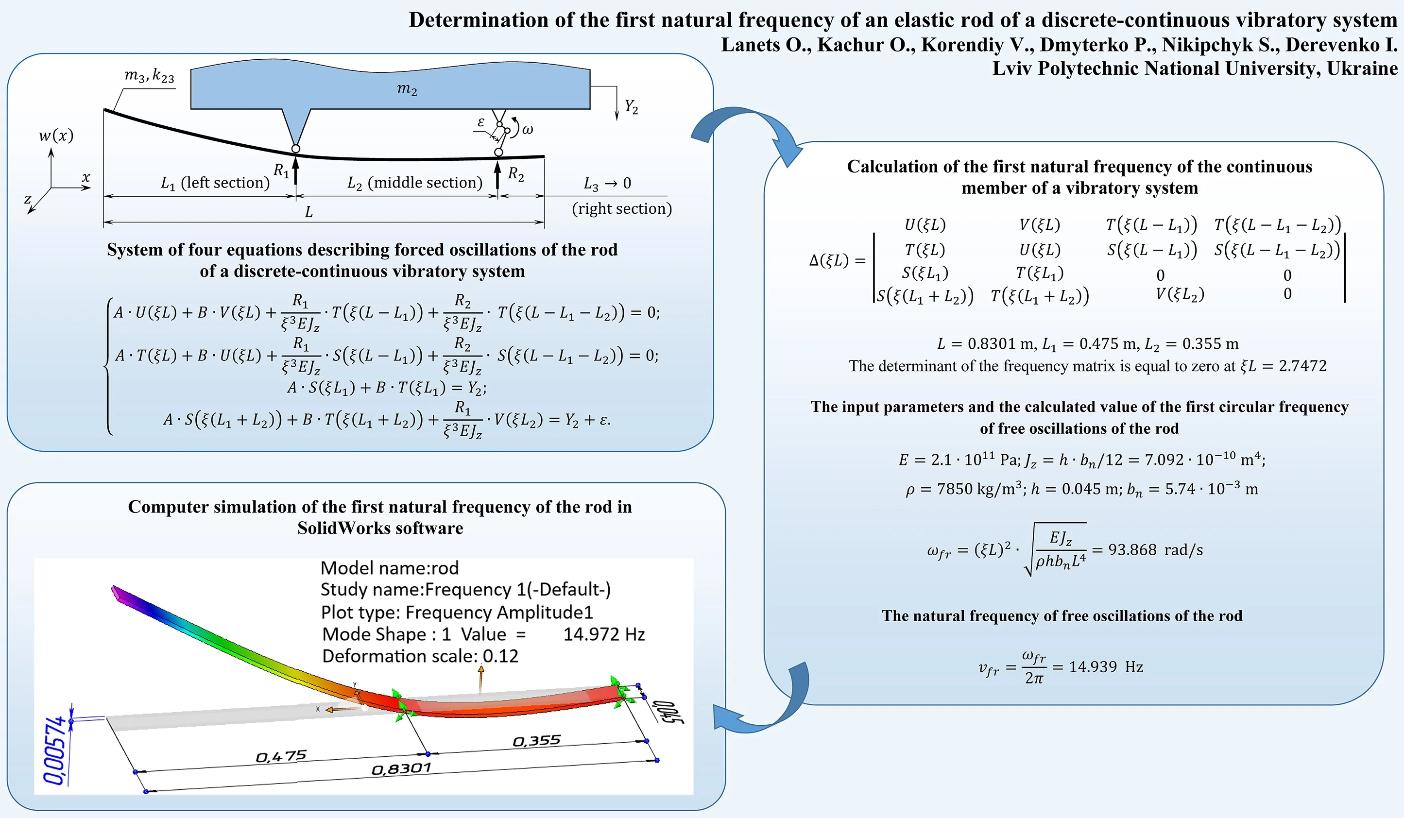
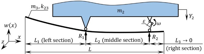
As a continuous member, there is taken a straight rod the dimensions of cross-section of which are small in comparison with its length. The suggested design diagram of fixation of the rod is like that shown in Fig. 1. The advantage of such a fixation is the fact that there exists a cantilever with considerable inertness (as to its length); such a cantilever can be set in motion mechanically. This can be ensured if one of the supports is disturbed by an eccentric drive [9]. This enables us to a priori assert that the virtually separated mass and rigidity will be accepted by the two-mass oscillatory system as a third independent mass, and the three-mass discrete-continuous oscillatory system will be an inter-resonance one.
Fig. 1Calculation diagram of a continuous rod-shaped member (a body with distributed inertia and rigidity parameters) considered as a disturbing body of the three-mass vibratory system
The determination of the natural frequency of a rod, as a beam which has three spans, is carried out in terms of the reactions and of the supports. As the reference point the left end of the rod is chosen; this left end is free (Fig. 1). The equations of deflections and in the middle section and in the right section, respectively, will be of the following form:
where is the deflection equation of the left section of the beam; is the modulus of elasticity of elongation for the material of the rod; is the moment of inertia of the cross-section of the rod about the neutral line of the section; , , are the lengths of the rod’s sections:
where is the density of the material of the rod; is the forced circular frequency; are the width and the thickness of the elastic rod, respectively.
In general, the deflection of a beam’s section can be described by the equation [10]:
where , , , are combinations of circular and hyperbolic functions (Krylov-Duncan functions); , , , are arbitrary constants.
For the middle and the right sections of the beam (see Eqs. (1-2)), the functions takes the following forms:
Since the left end of the rod is free, there take place lateral displacement and the angle of flexion ; the bending moment and the shear force are equal to zero.
The boundary conditions for the left free end of the beam are:
Thus, taking into account the boundary conditions Eq. (6-7), the general solution Eq. (4) in the left section takes the form:
Using Eq. (1), the deflection equation for the middle section assumes the form:
According to Eq. (2), for the right section the deflection equation is the following:
The Eq. (8-10) are written in general form. To determine the first natural frequency of the rod let us deduce a frequency equation. Let us form a system of four equations, which satisfy their corresponding boundary conditions at the ends of the rod and at the supports. Let us consider the free right end of the rod (Fig. 1). The boundary conditions of its fixation are:
Using Eq. (10) for , and taking into account the condition Eq. (12), let us form the first equation of the aforesaid system:
Using Eq. (10) for , and taking into account the condition Eq. (13), let us form the second equation of the aforesaid system:
Since there are four unknowns – constants , and reactions of the supports , – it is necessary to derive two more equations. Considering the vertical displacement of the left support (), where the reaction is equal to (Fig. 1), Eq. (8) can be written as:
Taking into account the vertical displacement of the right support (), where the reaction is equal to (Fig. 1), Eq. (9) can be written as:
From Eqs. (14, 16, 18, 20), the following system of four equations of forced oscillations of the rod is obtained:
3. Determination of first natural frequency of continuous member of vibratory system
From the system of Eq. (22), the determinant of the frequency matrix is formed:
A priory, the lengths 0.8301 m, 0.475 m, and 0.355 m are set; then, the determinant of the frequency matrix Eq. (23) is equal to zero at 2.7472.
The circular frequency of free oscillations of the rod, according to Eq. (3), is the following:
where 2.1∙1011 Pa; 7.092∙10-10 m4; 7850 kg/m3; 0.045 m; 5.74∙10-3 m.
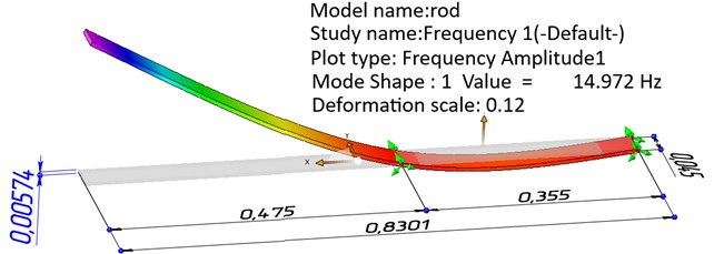
For a solid-body model of the rod, the first natural frequency of oscillations of the rod has been determined by means of Finite Elements Method in SolidWorks software ( 14.972 Hz) (Fig. 2).
The inaccuracy of the obtained results is scanty; therefore, it can be asserted that the rod-shaped continuous member is adequately in compliance with the discrete model (with the mass 0.313 kg and the stiffness coefficient 2.865∙103 N/m) ensuring the first natural frequency of the three-mass vibratory system of approximately 15 Hz [9].
Fig. 2Results of computer simulation of natural frequencies of the elastic rod in SolidWorks software
4. Conclusions
After considering a discrete model of the vibratory machine, the natural frequency concerning the oscillations of its reactive mass (disturbing body) can be determined; that frequency became an initial parameter which must be ensured by the continuous member. The simplified calculation diagram of the discrete-continuous vibratory system is shown in Fig. 1. In such a system, the elastic rod-shaped continuous member is fixed by hinged supports to the oscillating body; this enables us to disturb one of the supports by an eccentric-type vibration exciter.
According to classical theory of oscillations of elastic rods, having used the Krylov-Duncan functions, the mathematical model describing forced oscillations of the continuous member considered as a disturbing body of the three-mass discrete-continuous vibratory system has been established, and the corresponding frequency equation has been analytically derived. According to this equation, the decisive parameter for synthesis of the inter-resonance discrete-continuous vibratory system – the value of the first natural frequency in compliance with the natural frequency concerning the oscillations of the reactive mass of the discrete model – is established. This indicates that the rod-shaped continuous member is in compliance with the discrete model (with the mass 0.313 kg and the stiffness coefficient 2.865∙103 N/m) ensuring the first natural frequency of the three-mass vibratory system of approximately 15 Hz.
Computer simulation of natural frequencies of a rod-shaped continuous body has been carried out using Finite Elements Method in SolidWorks software; the obtained results (Fig. 2) are in satisfactory agreement with the results of analytical calculations (Eq. (24)).
The implemented prototype of a vibratory machine with a continuous member has generalized the results of analytical calculations and those of simulation; it confirmed the adequacy of the suggested theoretical principles.
References
-
Rajesh K., Saheb K. M. Large amplitude free vibration analysis of tapered Timoshenko beams using coupled displacement field method. International Journal of Applied Mechanics and Engineering, Vol. 23, Issue 3, 2018, p. 673-688.
-
Chen Li-Qun, Peng Li, Zhang A-Qiang, Ding Hu Transverse vibration of viscoelastic Timoshenko beam-columns. Journal of Vibration and Control, Vol. 23, Issue 10, 2015, p. 1572-1584.
-
Jaworski J. W., Dowell E. H. Free vibration of a cantilevered beam with multiple steps: comparison of several theoretical methods with experiment. Journal of Sound and Vibration, Vol. 312, Issues 4-5, 2008, p. 713-725.
-
Gharaibeh M. A., Obeidat A. M., Obaidat M. H. Numerical investigation of the free vibration of partially clamped rectangular plates. International Journal of Applied Mechanics and Engineering, Vol. 23, Issue 2, 2018, p. 385-400.
-
Joubaneh Eshagh F., Barry Oumar R., Tanbour Hesham E. Analytical and Experimental Vibration of Sandwich Beams Having Various Boundary Conditions. Shock and Vibration, Vol. 2018, 2018, p. 3682370.
-
Shi Xianjie, Shi Dongyan Free and forced vibration analysis of T-shaped plates with general elastic boundary supports. Journal of Low Frequency Noise, Vibration and Active Control, Vol. 37, Issue 2, 2018, p. 355-372.
-
Buchacz A. The supply of formal notions to synthesis of the vibrating discrete-continuous mechatronic systems. Journal of Achievements in Materials and Manufacturing Engineering, International OCOSCO World Press, Vol. 44, Issue 2, 2011, p. 168-178.
-
Gursky V., Kuzio I. Dynamic analysis of a rod vibro-impact system with intermediate supports. Acta Mechanica et Automatica, Vol. 12, Issue 2, 2018, p. 127-134.
-
Korendiy V., Lanets O., Kachur O., Dmyterko P., Kachmar R. Determination of inertia-stiffness parameters and motion modelling of three-mass vibratory system with crank excitation mechanism. Vibroengineering Procedia, Vol. 36, 2021, p. 7-12.
-
Lanets O. S., Kachur O. Yu., Korendiy V. М. Classical approach to determining the natural frequency of continual subsystem of three-mass inter-resonant vibratory machine. Ukrainian Journal of Mechanical Engineering and Materials Science, Vol. 5, Issues 3-4, 2019, p. 77-87.
Cited by
About this article

