Abstract
Military vehicles are required to negotiate drastic ride environments. Therefore, the vibration magnitudes which are transmitted to the vehicle chassis through the suspension system due to dynamic vehicle-terrain interactions, are usually large. Hence, it is necessary to study the vibrations that are transmitted to the sprung mass as it negotiates different types of terrain at different speeds. The present study is focused on the development of sprung mass non-linear pitch dynamics mathematical model of a military vehicle with a trailing arm torsion bar suspension system. The trailing arm kinematics and dynamics are incorporated into the non-linear governing equations of motion of the sprung and unsprung masses which consider the effects of sprung mass large pitch angular motions. The model is solved by coding in Matlab. The sprung mass non-linear pitch dynamics mathematical model is validated with an equivalent multi-body dynamics model which is developed by using MSC.ADAMS. This mathematical model would play a key role to fine-tune the vehicle and suspension parameters as well as comparatively evaluate the performance of the hydro-gas suspension system. The model can further be extended to include the military vehicle weapon recoil effects which can cause considerable magnitudes of vehicle pitch. Apart from simulating ride dynamics of the entire vehicle, the influence of movement with crane payload on the military recovery vehicle pitch dynamics can also be brought out as a useful extension of this mathematical model.
Highlights
- MBD Representation of single station torsion bar suspension.
- Dynamic Representation of sprung mass non-linear pitch dynamics mathematical model of a military vehicle with a trailing arm torsion bar suspension system.
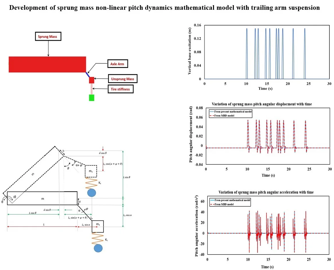
- Variation of vertical base excitation input with respect to time at the wheel bottom over APG at 20 kmph.
- Sprung mass pitch angular displacement variation with time from the mathematical and MBD models over APG at 20 kmph.
- Variation of sprung mass pitch angular acceleration with time from the mathematical and MBD models over APG at 20 kmph.
1. Introduction
Military vehicles are required to negotiate drastic ride environments. Therefore, the vibration magnitudes which are transmitted to the vehicle chassis through the suspension system due to dynamic vehicle-terrain interactions, are usually large. Hence it is necessary to study the vibrations that are transmitted to the sprung mass as it negotiates different types of terrain at different speeds. Gillespie had elaborately described the fundamental theory of vehicle dynamics in [1]. Gagneza and Sujatha had developed the 16 degrees of freedom ride dynamics mathematical model of an ICV BMP-II military tracked vehicle with torsion bar suspension to determine the vibration transmissibility due to road induced excitations and successfully validated the same with experimental findings in [2]. Dhir and Sankar had carried out the Lagrangian formulation of ride dynamics with an in-plane model of the tracked vehicle (Armoured Personal Carrier) over arbitrary rigid terrain profile at constant speed in [3]. Banerjee et al. had developed the non-linear ride dynamics mathematical model of the single suspension station of a military vehicle by incorporating the trailing arm dynamic behavior of the hydro-gas suspension in the governing equations of motion, and thereafter validating the same with an equivalent multi-body dynamic model over standard terrain inputs in [4]. The difference of dynamic performance with an equivalent vertical configuration of the suspension system was highlighted in the study. The 17 degrees of freedom full military vehicle ride dynamics model with trailing arm dynamics of the hydro-gas suspension and inertia coupling effects, was developed by Banerjee et al. in [5]. Parametric evaluation of ride dynamics was carried out to evaluate the frequency weighted ride comfort characteristics in [5]. Even though the actual trailing arm dynamics of the hydro-gas suspension and inertia coupling effects were considered in [4], the main focus was to evaluate the sprung mass bounce dynamics under the influence of unsprung mass rotational motion, which simplified the mathematical formulation of including the inertia coupling effects. The large pitch angular motion of the sprung mass was not considered in [5], which would affect the formulation of the sprung and unsprung mass inertia coupling effects. Yamakawa and Watanabe had carried out spatial motion analysis of high speed tracked vehicles with torsion bar suspension for the evaluation of ride performance, steerability and stability on rough terrain [6].
It is observed from the above studies that significant research was taken up in the field of military vehicle dynamics under the influence of torsion bar suspension systems. In most of the reported literature, the trailing arm suspension dynamics is converted to its equivalent vertical configuration in which the sprung and unsprung mass inertia coupling effects are absent. The effects of sprung mass large pitch angular motion which is induced by virtue of the trailing arm motion are also not considered in most of the studies. The present model is focused on the development of the sprung mass non-linear pitch dynamics mathematical model under the influence of the trailing arm torsion bar suspension. The mathematical model consists of two degrees of freedom namely, sprung mass pitch angular displacement and unsprung mass angular displacement. The inclusion of sprung mass large pitch angular displacement provides a much more accurate formulation of inertia coupling unlike that described in [4, 5]. A multi-body dynamic (MBD) model of the single station with torsion bar suspension is developed in MSC.ADAMS which establishes a numerical experimental platform to validate the non-linear mathematical model.
2. Description of single station torsion bar suspension system
The torsion bar suspension system comprises the sprung mass and unsprung mass which are shown in Fig. 1. The sprung mass is hinged at the extreme end. Being a torsion bar suspension, constant torsional stiffness is considered in the non-linear mathematical vibration model. Solid tire is represented by linear vertical spring with high stiffness in the equations of motion. The tire vertical spring establishes connectivity of the unsprung mass with the ground. The solid tire damping effects are negligible and are therefore not considered in the mathematical model. Viscous torsional damping is assumed in the suspension system.
Fig. 1Schematic representation of the single station torsion bar suspension system
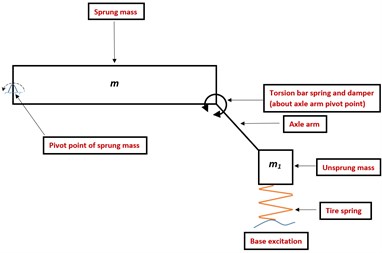
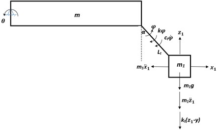
Fig. 2Representation of dynamic behavior of the single torsion bar suspension station due to base excitation
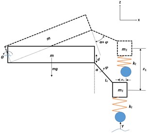
The trailing arm torsion bar suspension model is developed with axle arm under rebound condition at an angle with the vertical. The sprung mass executes large pitch angular motion about its hinge point in the - plane (indicated in Fig. 2). The unsprung mass also executes angular motion about its hinge point in the plane of the paper. Even though constant torsional stiffness value is considered, the non-linearities exist in the mathematical model due to sprung mass large pitch angular motion and trailing arm angular motion about their respective hinge points. The non-linear vibration mathematical model consists of two degrees of freedom, namely sprung mass large pitch angular displacement and unsprung mass angular displacement. By virtue of angular motion about the pivot point, the unsprung mass possesses both vertical and horizontal inertias which affect the sprung mass pitch behaviour. Similarly, the sprung mass large pitch angular motion about its pivot point affects the unsprung mass angular motion. The inertia coupling effects appear due to the trailing arm connection in the suspension system. The unsprung mass angular motion is analogous to that of a pendulum which is supported by a torsional spring and damper about its hinge point. With reference to rebound configuration, the axle arm rotates by an angle and the sprung mass exhibits large pitch angular displacement about its hinge axis while the road wheel is subjected to the terrain excitations. The gravity effect is brought inside the formulation. Therefore, the static equilibrium configuration of the system is obtained under the effect of gravity. Subsequent to the static settlement, suitable base excitations are applied to the non-linear vibration mathematical model. The nomenclature of various parameters that are used in the non-linear vibration mathematical model of the single station, is shown in Table 1.
Table 1Description of the variables
Variable | Definition |
Sprung mass | |
Unsprung mass | |
Linear vertical stiffness of the road wheel tire | |
Stiffness of the torsion bar | |
Damping coefficient of the torsion bar | |
Distance between sprung mass hinge axis and extreme end | |
Axle arm length | |
Rebound angle | |
Vertical distance from axle arm pivot to sprung mass hinge | |
Axle arm rotational angle from rebound position | |
Sprung mass pitch angular displacement | |
Base excitation from terrain |
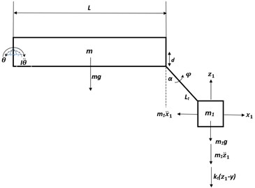
The free-body diagram which represents sprung mass pitch angular motion and unsprung mass angular motion along with the associated forces and moments which account for moment balance about their respective hinge point, is highlighted in Fig. 3(a) and 3(b).
Fig. 3Free body diagram of single station torsion bar suspension model which highlights forces and moments on sprung and unsprung mass
a)
b)
3. Equations of motion of sprung mass pitch dynamics of trailing arm with torsion bar
Referring to Fig. 3(a), the sprung mass pitch motion about its hinge axis is expressed as:
where is the sprung mass moment of inertia about its hinge axis, and are the unsprung mass horizontal and vertical displacements, respectively, which results from the sprung and unsprung mass coupled dynamic behavior and is expressed as:
and , are the moments due to unsprung mass vertical and horizontal inertias (determined at unsprung mass CG), respectively, about the sprung mass hinge axis, is the moment due to the road-wheel vertical spring restoring force (determined at unsprung mass CG), about the sprung mass hinge axis, is the moment induced by sprung mass self-weight about its hinge axis, is the moment due to unsprung mass self-weight about the sprung mass hinge axis.
The second order coupled governing differential equation of motion which represents unsprung mass rotational motion about its hinge point (referring to Fig. 3(b)), is written as:
where and are the moments due to unsprung mass vertical and horizontal inertias (determined at unsprung mass CG), respectively, about its pivotal axis, is the moment due to road wheel vertical spring restoring force (determined at unsprung mass CG) about the unsprung mass pivotal point, is the moment due to unsprung mass self-weight about its pivotal axis, is the moment about unsprung mass hinge axis due to torsional stiffness of the torsion bar, is the moment about unsprung mass hinge axis due to suspension torsional viscous damping.
The non-linear vibration mathematical model of the torsion bar trailing arm suspension is coded in MATLAB and similar solver techniques are used as described in Banerjee et al. in [5].
4. Development of MBD model of the single station torsion bar suspension system
The MBD model of the torsion bar trailing arm suspension is developed in MSC. ADAMS (shown in Fig. 4) in order to provide a numerical experimental platform for validating the non-linear mathematical model. It consists of a torsion bar suspension with constant torsional stiffness. Similar to the mathematical model, viscous torsional damping is assumed for the torsion bar suspension system in the MBD model which is developed in the initial rebound position. Suitable base excitations are applied as a function of time to the road-wheel linear vertical spring in the MBD model of the torsion bar trailing arm suspension system. The solution technique of the MBD model is similar to that described in Banerjee et al. in [4].
Fig. 4MBD model of single torsion bar suspension station
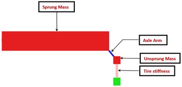
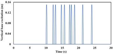
Fig. 5Variation of vertical base excitation input with respect to time at the wheel bottom over APG at 20 kmph
5. Dynamic response comparison between the non-linear mathematical model and MBD model
The mathematical and MBD models of the torsion bar trailing arm suspension are simulated over Aberdeen Proving Ground (APG) at speeds of 20 kmph. The sprung mass () and unsprung mass () of the single station torsion bar suspension model are 2000 kg and 250 kg, respectively. The rebound angle () is 42°. The spring stiffness () and the damping coefficient () of the torsion bar are 10.05 Nm/rad and 1000 Nms/rad, respectively. The linear vertical stiffness of the road wheel is 8000 kN/m. The distance between the sprung mass hinge axis and extreme end () is 3 m. The axle arm length () is 0.35 m and the vertical distance from axle arm pivot to sprung mass hinge () is 0.25m.
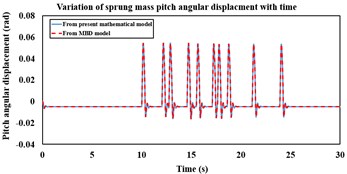
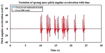
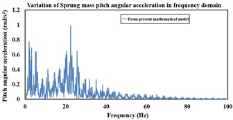
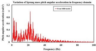
Fig. 6a) Sprung mass pitch angular displacement variation with time from the mathematical and MBD models over APG at 20 kmph, b) variation of sprung mass pitch angular acceleration with time from the mathematical and MBD models over APG at 20 kmph, c) variation of sprung mass pitch angular acceleration in frequency domain from the mathematical model over APG at 20 kmph, d) frequency domain variation of sprung mass pitch angular acceleration from the MBD model over APG at 20 kmph speed
a)
b)
c)
d)
The mathematical vibration model of the torsion bar trailing arm suspension is simulated over APG (shown in [4]) at 20 kmph for 30 s and the sprung as well as unsprung mass responses are compared with that from the MBD model. APG induced base excitation which corresponds to vehicle speed of 20 kmph, is applied to the road-wheel vertical spring and highlighted in Fig. 5. Fig. 6(a) highlights the sprung mass comparative pitch angular displacements which are obtained from both mathematical and MBD models. The sprung mass pitch angular acceleration response comparison in both time and frequency domains between the non-linear mathematical and MBD models, are shown in Fig. 6(b), 6(c) and 6(d) respectively.
It is observed from Fig. 6(a), 6(b), 6(c) and 6(d) that the non-linear mathematical model of the torsion bar trailing arm suspension is in close agreement with its equivalent MBD model. The sprung mass peak pitch angular acceleration magnitudes that are obtained from the non-linear mathematical and equivalent MBD models at 20 kmph speed are 42.04 rad/s2 and 42.23 rad/s2, respectively. The RMS sprung mass pitch angular acceleration obtained from the non-linear mathematical and equivalent MBD models at 20 kmph are 5.99 rad/s2 and 6.01 rad/s2, respectively.
6. Conclusions
The sprung mass non-linear pitch dynamics mathematical model is developed under the influence of the trailing arm torsion bar suspension. The sprung mass dynamic responses from the non-linear vibration model compare well with that obtained from the equivalent MBD model. The equivalent MBD model may be considered as a numerical experiment that is solved through implicit time integration scheme. Small amount of deviation in the responses which are obtained from both the mathematical and MBD models, may be attributed to numerical differences in the solver techniques. Parametric sensitivity analyses can be carried out with the present mathematical model through which various suspension design configurations can be frozen. The comparative dynamic performance between hydro-gas and torsion bar suspensions can be evaluated through this mathematical model. The model can further be extended to include the military vehicle weapon recoil effects which can cause considerable magnitudes of vehicle pitch. Apart from simulating ride dynamics of the entire vehicle, the influence of movement with crane payload on the military recovery vehicle pitch dynamics can also be brought out as a useful extension of this mathematical model.
References
-
Gillespie T. D. Fundamentals of Vehicle Dynamics. USA: Society of Automotive Engineers, 1992.
-
Gagneza G. P., Chandramohan S. Estimation of road loads and vibration transmissibility of torsion bar suspension system in a tracked vehicle. Journal of The Institution of Engineers (India): Series C, Vol. 100, Issue 5, 2019, p. 747-761.
-
Dhir A., Sankar S. Assessment of tracked vehicle suspension system using a validated computer simulation model. Journal of Terramechanics, Vol. 32, Issue 3, 1995, p. 127-149.
-
Banerjee S., Balamurugan V., Krishna Kumar R. Ride dynamics mathematical model for a single station representation of tracked vehicle. Journal of Terramechanics, Vol. 53, 2014, p. 47-58.
-
Banerjee S., Balamurugan V., Krishna Kumar R. Ride comfort analysis of math ride dynamics model of full tracked vehicle with trailing arm suspension. Procedia Engineering, Vol. 144, 2016, p. 1110-1118.
-
Yamakawa J., Watanabe K. A spatial motion analysis model of tracked vehicles with torsion bar type suspension. Journal of Terramechanics, Vol. 41, Issues 2-3, 2004, p. 113-126.
Cited by
About this article

The authors would like to thank Dr. Sivakumar R, Dean, School of Mechanical Engineering of Vellore Institute of Technology, Chennai for their continuous support and encouragement during this research work. The authors are also grateful to Shri. Balamurugan V, Director, CVRDE, Shri. Murugesan R, Addl. Director (CEAD) and Shri. Hameed Faizul A, Sc ‘E’ (Mechanical Systems Laboratory) for extending all required facilities to carry out the research work. The authors express their gratitude to Dr. V. Balamurugan, Addl. Director (AP) and Dr. R. Krishna Kumar, Professor, IIT Madras for their valuable guidance and consultancy in the field of vehicle dynamics.
