Abstract
This paper analyzes the dynamical behavior of a six-bar linkage used in mechanical presses for metal forming such as deep drawing. Raising the technical level of machines requires an expansion of technological capabilities of the equipment and devices of the existing structures, as well as their equipping with fundamentally new mechanisms. In this regard, the task of developing methods for the dynamic of complex flat lever mechanisms with the desired laws of motion of the input and output elements allowing automatizing the implementation of all design phases with the use of computer is quite relevant. The simulation results obtained with a Maple program are validated by comparing the theoretical values of the input moment with the ones obtained from the conservation of energy law. Content of the article is distinguished by serious problem statement, interesting theoretical study and its practical test. This article provides new scientific results that have theoretical and applied significance.
1. Introduction
The work is carried out using various techniques, as well as techniques and their computer programming of kinematic analysis [1]. The more complicated device of the lever transmission, the analysis and synthesis of such mechanisms will be difficult [2]. Therefore, a two-part structural group will be used for practice [3]. Leverage consists of the main mechanism consisting of four parts of the structural group; their application in technology will not be [5, 6]. The reason is, the difficulty of distributing the practice of design engineers in the field of investigation of the mechanism from the structural group of four parts [7-9]. Automation and automatic press is carried out by means of processing of the two-lever mechanism of the structural group functionality [10-12]. In this regard, based on the structural group of four parts, mechanisms and planning machines, the synthesis of dynamic planning, processing of a numerical algorithm is a versatile issue, consisting of a structural group of four parts [13, 14].
2. Materials and methods
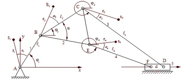
Dynamical equations on the first degree of freedom of the mechanism can be calculated from the basis of the algorithmic system without resorting to the cumbersome approach of solving the reduced force and mass [1]. The approach excludes the process of differentiating cumbersome expressions and allows us to construct an explicit dynamic equation with fairly good approximations [2]. The executive mechanism of the exhaust press machine is a flat crank-and-rod mechanism of the fourth class, represented in Fig. 1.
In a variant of the dynamic equation on the first degree of the mechanism is presented:
where – accumulated coordinates, , the reduced moment of inertia and its production from the accumulated coordinates, , The forces accumulated in motion and accordingly resistance forces [3-4]. In this algorithm Eq. (1) the d’Alembert-Lagrange equations are applied:
Fig. 1Kinematic model of six-bar mechanical press
On the basis of Eq. (2) from Eq. (1), by means of variation, it is possible to obtain discrete values of the inertia moment and its derivative, as well as the reduced moment of the resistance force mechanism [5-7]. The digital calculated algorithm of the mechanism includes the following main values: the equations of motion of a strictly secured press machine are indicated below [8-10]. Positioning function: , , , . Is determined by the formula:
and we use the following equation to determine the quantitative structure of the mechanism:
where:
The mechanism connects the center of the mass coordinates using the following formula:
Than we determine by the formula of analogue velocity:
by agreement.
where:
and so:
, by agreement:
Accordingly, we define the velocity analogue with the following formula:
where:
and more:
In general the angular velocity , and acceleration , . Speed and acceleration of the 5 (F) wet by the speed and acceleration of the engine joints 1 generation [11, 12], with the following formula:
where , angular velocity and angular acceleration of the drivers joints [13].
The complex movement of the mechanism , accepted for permanently movement:
and in the initial movement:
We determine the velocity and accelerations of the center of gravitation of the link [14] accordingly Eq. (8-10) on the basis of Eq. (20):
where:
3. Results and discussion
According to the 3D Maple program, you can see the enlarged internal structure of the planned new type of automatic press of the hammer-stamping mechanism, considering the scheme, during the work of the links the main role of the parts; we see that each force is affected by different forces, thereby losing its workforce. And also, relying on the path of analytics and kinematics, we do not the effect to the link mechanism, but the values that we do not take into account have a significant effect on the mechanism, and so that all the values have been taken into account we come to the aid of the Maple program (see Fig. 2-8).
Fig. 2Six bar linkage motion simulation in Maple
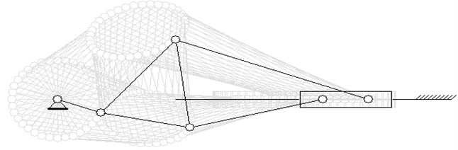
Fig. 3Computed plot of the crank angular velocity
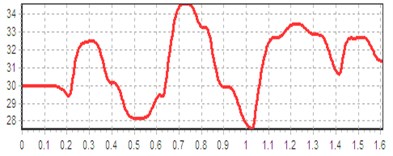
Fig. 4Computed plot of the pressure
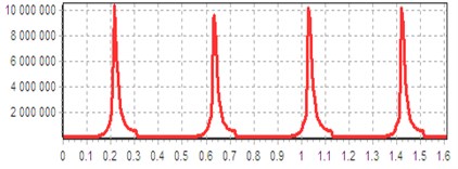
Fig. 5Computed plot of the moments of driving forces and resistance forces
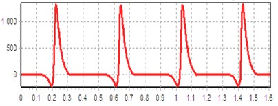
Fig. 6Computed plot of the power on the internal combustion engine shaft
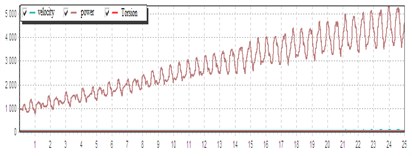
Fig. 7Computed plot of the dynamic characteristics of the engine
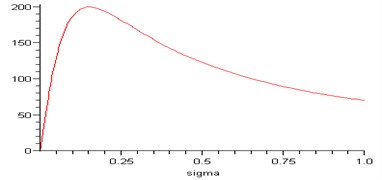
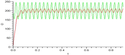
Fig. 8Computed plot of the angular velocity of rotor and motor moment
4. Conclusions
In the current study, the dynamic analysis of a six-bar linkage of a mechanical press for deep drawing has been investigated developing a Maple program. Raising the technical level of machines requires an expansion of technological capabilities of the equipment and devices of the existing structures, as well as their equipping with fundamentally new mechanisms. Creation and implementation of new structures of industrial robots, equipment for light industry, mining, and oil and gas industry requires the use of mechanisms with a complicated motion of actuating devices. In this regard, the task of developing methods for the kinematic and dynamic of complex flat lever mechanisms with the desired laws of motion of the input and output elements allowing automatizing the implementation of all design phases with the use of computer is quite relevant.
References
-
Yan H. S., Chen W. R. A variable input speed approach for improving the output motion characteristics of Watt-type presses. International Journal of Machine Tools and Manufacture, Vol. 40, 2000, p. 675-687.
-
Yan H. S., Chen W. R. Optimized kinematics properties for Stevenson-type presses with variable input speed approach. Journal of Mechanical Design, Vol. 124, 2002, p. 350-360.
-
Hsieh W. H., Tsai C. H. On a novel press system with six links for precision deep drawing. Mechanism and Machine Theory, Vol. 46, 2011, p. 239-251.
-
Soong R. Ch. A new design for single DOF mechanical presses with variable speeds and length-adjustable driving links. Mechanism and Machine Theory, Vol. 45, 2010, p. 496-511.
-
Yossifon S., Shivpuri R. Analysis and comparison of selected rotary linkage drives for mechanical presses. International Journal of Machine Tools and Manufacture, Vol. 33, 1993, p. 175-185.
-
Yossifon S., Shivpuri R. Design considerations for the electric servo-motor driven 30 ton double knichle press for precision forming. International Journal of Machine Tools and Manufacture, Vol. 33, 1993, p. 209-225.
-
Tso P. L., Liang K. C. A nine-bar linkage for mechanical forming presses. International Journal of Machine Tools and Manufacture, Vol. 42, 2002, p. 139-156.
-
Li H., Zhang Y. Seven-bar mechanical press with hybrid-driven mechanism for deep drawing Part 2 Dynamic modelling and simulation. Journal of Mechanical Science and Technology, Vol. 24, 2010, p. 2161-2182.
-
Mitsi S, Tsiafis I., Bouzakis K. D. Force analysis of six-bar linkage for mechanical presses considering joint frictions. Journal of the Balkan Tribological Association, Vol. 21, 2015, p. 281-295.
-
Zhauyt A. The substantiating of the dynamic parameters of the shaking conveyor mechanism. Vibroengineering Procedia, Vol. 5, 2015, p. 15-20.
-
Askarov E. Zhauyt A., Abilkaiyr Zh., Zhankeldi A., Naurushev B. A new type cam-screw mechanical press. Engineering for Rural Development, Vol. 16, 2017, p. 36-41.
About this article

