Abstract
It is necessary to make link mechanisms calculation to the strength at designing of flat link mechanisms of high class after definition of block diagrams and link linear sizes i.e. it is rationally to choose their forms and to determine the section sizes. The algorithm of the definition of dimension of link mechanism lengths of high classes (MHC) and their metric parameters at successive approach is offered in this work.
1. Introduction
At the solution of synthesis problems of transfer mechanism with the difficult transfer function including stops of the output link, we often come to the third class link mechanism. This mechanism can be considered formally as a four-bar linkage with a variable length of the piston rod, then implementation of difficult laws of the movement is obviously reached. It is necessary to know point functions and transfer functions of all links for the further dynamic investigation of these mechanisms. The vector method of the kinematic analysis of the third class mechanism based on the principle published in the work, is offered. We represent link length of the mechanism in the form of vectors, as shown in Fig. 1. We make four independent vector equations of circuit completeness.
Fig. 1The kinematic scheme of six-bar mechanism, φo – generalized coordinate; φi(i=1,2....5) – points of link mechanism which are defined by the method of the conditional generalized coordinates
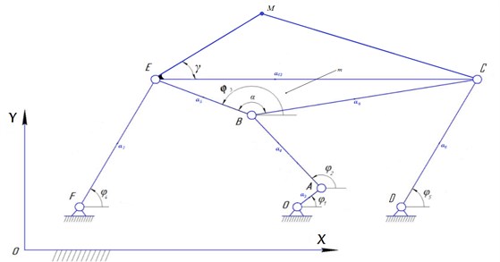
It is necessary to find errors of piston rod point of the studied third class mechanism occurring in metric parameters: , , , , , , , , , , , , .
We write down coordinates of point:
The errors of the point position is defined by formulas:
where – length error, – link:
For finding of private derivatives in Eq. (3) we consider system of the equations:
and differentiate on . From where we receive:
then:
where:
We substitute the received values of private derivatives in equality Eq. (3), after that we define errors of the point position .
The maximum error of the conrod point position coming from errors in all metric parameters:
The algorithm of the solution of the task of the kinematic analysis of the third class mechanism is made on the basis of the derived formulas. The replacement of the rotary guide link on the progressive doesn’t make essential changes to formulas of kinematic analysis. This technique was used at kinematic and dynamic investigations of concrete transform mechanism of the third class.
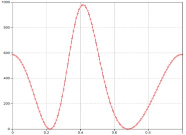
Fig. 2Computed plot of the M point velocity module
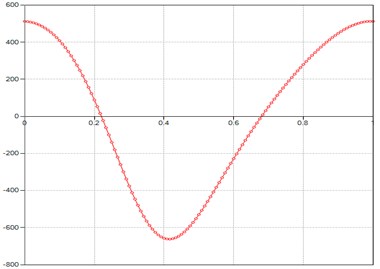
Fig. 3Computed plot of the M point acceleration module
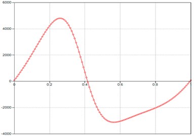
Fig. 4Computed plot of the M point tangent acceleration module
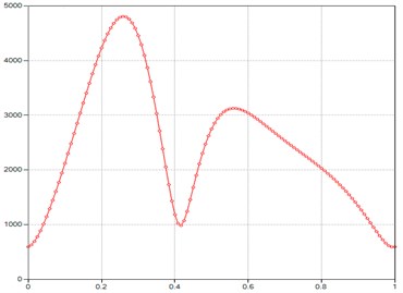
Fig. 5Computed plot of the M point normal acceleration module
2. Results and discussion
In this paper, a kinematic model of the third class Assur group is presented. The method has the property of visibility, which makes it suitable for use in engineering practice. Simulation of the kinematical analysis of third class plain lever mechanism with output dwell is done using Model GIM software application that gives opportunity to develop discrete, continuous and hybrid models of complicated technical systems.
Fig. 6Computed plot of the M point velocity Phi
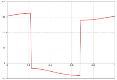
Fig. 7Computed plot of the M point acceleration Phi
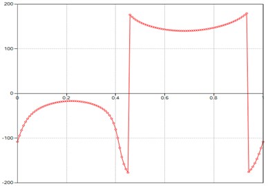
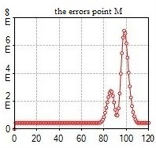
Fig. 8Computed plot of the errors point M
3. Conclusions
The combined analytic and graphic-analytical kinematic analysis method of the sixth class third order mechanism can be performed by accepting the inverse motion, considering the input element of the original mechanism as frame and one of the adjacent ternary element as drive element. The analysis of the mechanism is reduced to the study of third and second class Assur kinematic groups. The positional kinematic analysis shows that the most difficult problem is the solving of a trigonometric equations system by means of numerical methods. The kinematic analysis of a particular case indicated by Artobolevsky highlights the difficulties in computing the velocities in particular positions. However, some properties of the mechanism recommend it to be used in applications which need the preservation of parallel positions of the higher order couplers in self-locked extreme position and its compact size in folded position.
References
-
Zhauyt Algazy, Alipov Kuanyshkali, Sakenova Aizhan, Zhankeldi Adilet, Abdirova Raushan, Abilkaiyr Zhastalap The synthesis of four-bar mechanism. Vibroengineering Procedia, Vol. 10, 2016, p. 486-491.
-
Zhauyt Algazy The substantiating of the dynamic parameters of the shaking conveyor mechanism, Vibroengineering Procedia, Vol. 5, 2015, p. 15-20.
-
Yang X. L., Wu H. T., Li Y., Chen B. A dual quaternion solution to the forward kinematics of a class of six-DOF parallel robots with full or reductant actuation. Mechanism and Machine Theory, Vol. 107, 2017, p. 27-36.
-
Joldasbekov Skanderbek, Ibraev Sayat, Zhauyt Algazy, Nurmagambetova Aiman, Imanbaeva Nurbibi Modular synthesis of plane lever six-link mechanism of high class. Middle-East Journal of Scientific Research, Vol. 21, Issue 12, 2014, p. 2339-2345.
-
Wang Z., He J., Shang H., Gu H. Forward kinematics analysis of a six-DOF Stewart platform using PCA and NM algorithm. Industrial Robot: An International Journal, Vol. 36, 2009, p. 448-460.
-
Zhauyt Algazy, Mamatova Gulnar, Alipov Kuanysh, Sakenova Aizhan, Abdirova Raushan The kinematic analysis of flat lever mechanisms with application of vector calculation. Vibroengineering Procedia, Vol. 8, 2016, p. 1-5.
-
Cabrera J. A., Simon A., Prado M. Optimal synthesis of mechanisms with genetic algorithms. Mechanism and Machine Theory, Vol. 37, 2000, p. 1165-1177.
-
Lin W.-Y. A GA-DE hybrid evolutionary algorithm for path synthesis of four-bar linkage. Mechanism and Machine Theory, Vol. 45, 2008, p. 1096-1107.
-
Lipson H. Evolutionary synthesis of kinematic mechanisms. Artificial Intelligence for Engineering Design, Analysis and Manufacturing, Vol. 22, 2006, p. 195-205.
Cited by
About this article

