Abstract
This paper proposes a novel design of a high order closed-loop Sigma-Delta modulator using a fractional-order disturbance observer, which can reduce the influence of possible dispersions of the sensing element and offset the effect of the external disturbance. The proof mass can maintain near its position of equilibrium by using the proposed fractional-order disturbance observer, which ensures a better control of the proof mass displacement, and the small proof mass displacement can enhance the sensor resolution and the overall system performance. Fractional-order disturbance observer possesses stronger robust stability of interference elimination, because the introduction of fractional calculus makes Q-filter expanding from an integer domain to a real-number domain. Experimental results from the proposed architecture shows an increase of more than 2X improved in signal quantization noise ratio compared to the pure high-order closed-loop Sigma-Delta modulator, and also the proposed Sigma-Delta modulator with a fractional-order disturbance observer improves the performance of disturbance attenuation and system robustness.
1. Introduction
The fast development of micro-processing and integrated circuit technology were the main driver of the widely application for the MEMS (Micro-Electromechanical System) accelerometer [1, 2]. MEMS accelerometers are commonly used in automotive applications, biomedical domain and navigation system [3-5] thanks to their small size, low cost, and low power consumption, etc. MEMS accelerometers using a capacitive sensing element incorporated in Sigma-Delta () modulator closed-loop control systems with electrostatic feedback. MEMS accelerometer systems consist of chips developed separately may not work properly together when they were integrated together even each chip might be designed and optimized in its own develop project. MEMS accelerometer requires system level integrated design and development. As we all know that an advanced MEMS accelerometer system contains several features such as (1) feedback system with MEMS sensor in the loop; (2) system with sensing and digitization in one step; (3) system with multi-physics principles; (4) - closed-loop system with force rebalance.
Among various techniques for implementing the MEMS accelerometer, modulator provides the combined benefits of force feedback and inherent analog-to-digital conversion [6]. The sensing element of MEMS accelerometer can be modeled as a mass-spring-damper system, which provides a 2nd order dynamics. Therefore, a traditional MEMS accelerometer is mainly focused on using the sensing element as a low-pass filter to form a 2nd order modulator [7]. At present, many researchers have mainly focused on using the additional electronic integrator as a loop integrator to form the high order closed-loop modulator to improve its SNR and noise performance [8]. There are a lot of advantages to the high order closed-loop modulator, nevertheless such this architecture may suffer from the overall system instability. As discussed, a modulator, which can both achieve high SNR, outstanding noise performance and also ensure the system stable, is much difficulty to be designed. It is shown that the Sigma-Delta modulator system can be studied as a nonlinear dynamical system with feedback control [9]. Representing a modulator as “plant” and “controller” transforms a modulator design problem into a control design problem. Therefore, many researchers introduced several advanced control techniques to Sigma-Delta modulator. In ref [10, 11], a high-order Sigma-Delta modulator design by slide mode control is proposed, which can precisely predict the modulator performs and reduce the nonlinear effect from the 1-bit comparator; In ref [12], a Kalman state estimator is applied to a Sigma-Delta micro-accelerometer which can enhance the resolution of the Sigma-Delta modulator. In this paper, we present an approach that ensures a better control of the proof mass displacement thanks to the proposed fractional-order disturbance observer, which is able to improve the noise performance and system robust stability.
In practice, a physical motion system cannot be exactly the same as any mathematical model, no matter how the model is obtained [13]. In the system of a MEMS accelerometer, a precise mathematic model of the sensing element which may not be readily available because of the external disturbance (temperature, pressure) or dispersions in the manufacturing process. Thus, the mismatch between the real and ideal parameters can result in relatively large proof mass displacements and as a consequence in a decrease of the overall system performance. The concept of disturbance observer (DOB) was proposed in ref [14], which is able to improve the ability of disturbance rejection. The filter in DOB belongs to the low-pass filter called Q-filter. The so-called Q-filter has three adjustable parameters, including the order, the relative degree and the bandwidth. Therefore, compared to integral action, DOB offers more opportunities to improve the performance of the control system (rapidity, stability, phase shift etc.) through tuning the three parameters of Q-filter. In ref. [15], a fractional-order disturbance observer (FO-DOB) based on a fractional-order Q-filter was proposed and thus extending the integer-order disturbance observer to a new fractional-order one. The fractional-order Q-filter is employed to make a tradeoff between the robust stability and the disturbance suppressing force. Therefore, in this paper, FO-DOB is employed to observe and compensate the disturbances and model mismatch of the sensing element, which is able to make the overall system have better robust stability against variation of mathematic model of the sensing element and then ensure MEMS accelerometer achieve high SNR and satisfactory noise performance.
The remainder part of this paper is organized as follows: in Section 2, a basic architecture of FO-DOB and parameters design in FO-DOB are introduced; in Section 3, the proposed design of a high order closed-loop modulator with a FO-DOB is presented. Then simulation results of the proposed design architecture are demonstrated and analyzed in Section 4. Finally, conclusions are given in Section 5.
2. Continuous-time fractional-order disturbance observer
The basic idea of the conventional DOB is to apply a nominal inverse model of the plant to observe the disturbance which caused by external interference and parameters variation, and then an equivalent compensation is generated by DOB. The basic architecture of DOB is depicted in Fig. 1.
In Fig. 1, is the transfer function of the plant model, is the equivalent disturbance, is the observing value of , and are the input and output of DOB, respectively. By observation from Fig. 1, the observing value can be written as:
Unfortunately, the implementation of the conventional DOB encounters three key problems in a practical system [8] as follows:
1) In general cases, the relative order of is not equal to zero, therefore the inverse of the plant model cannot be obtained.
2) The transfer function of the plant model cannot describe the practical system precisely, that is to say is not totally accurate.
3) The existence of the measurement noise will deteriorate the control performance of control system.
In order to solve the above three problems, a Q-filter and a transfer function are introduced, which is shown as in Fig. 2.
Fig. 1Basic architecture of DOB
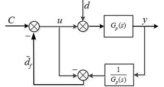
Fig. 2Block diagram of DOB
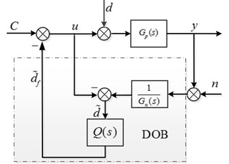
In Fig. 2, is a low-pass filter, which is used to restrict the effective bandwidth of DOB. and are the disturbance observe before and after by the Q-filter.
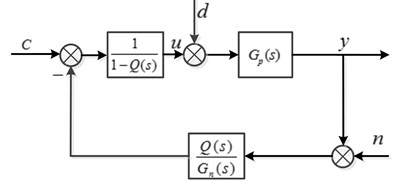
From the conventional DOB shown in Fig. 2, the signal transfer function , the disturbance transfer function and the noise transfer function can be written as:
where, we assume that the cutoff frequency of the low-pass Q-filter is . When , , taking into Eqs. (2), (3) and (4), the signal transfer function , the disturbance transfer function and the noise transfer function ; and when , , taking into Eqs. (2), (3) and (4), the signal transfer function , the disturbance transfer function and the noise transfer function . By observation from , and , we can find that the external disturbance can be suppressed by designing the low-pass Q-filter. In other words, the design of Q-filter is a key part in DOB design. In particular, the relative order of the low-pass Q-filter should be more than that of to maintain being a regular rational transfer function, and the bandwidth design of Q-filter should make a tradeoff between robust stability and disturbance elimination force of the overall system.
The relation between the real model and ideal model can be expressed by:
where is a uncertain transfer function, which contains variable parameters of the plant model. The robust stability criterion of the uncertain system is discussed in [16], the sufficient criterion of robust stability for Q-filter is expressed as follows:
In order to simplify design process of the low-pass Q-filter, an equivalent block diagram of DOB is shown in Fig. 3.
Fig. 3Equivalent block diagram of DOB
It can be seen from the block shown in Fig. 3, the disturbance observer is a high gain technique when . To simplify the analysis of uncertain transfer function , here we assume is the only source of uncertain dynamics, so can be rewritten as:
By observation from Eqs. (5) and (7), the uncertain transfer function is written as:
In this paper, the low-pass filter can be expressed as:
where cutoff frequency , here we set 0.2 ms, 50 rad/sec, 100 rad/sec, 500 rad/sec, so the uncertain transfer function and three are rewritten as follows:
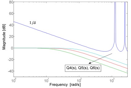
The robust stability of DOB with respect to the cutoff frequency of is depicted in Fig. 4.
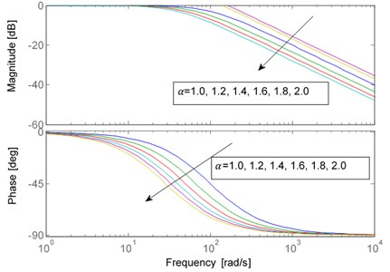
It is obvious from Fig. 4 that the robust stability criterion Eq. (6) is violated when 500 rad/sec. The magnitude responses of and are below the curve of , so the robust stability criterion can be satisfied when 100 rad/sec. Also, here we set 0.2 ms, 100 rad/sec and 1, 2, 3 to inspect the variations of the robust stability of DOB with respect to relative order of the . Fig. 5 shows three curves with different relative order 1, 2, 3.
Fig. 4The robust stability of DOB with different cutoff frequency
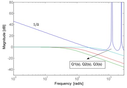
Fig. 5The robust stability of DOB with different orders
By observation from Fig. 5, the higher relative order of , the better robust stability of DOB. In ref. [14], the cutoff frequency is always determined according to the disturbance attenuation requirement in advance. Therefore, the relative order of the low-pass is the only knob to design. As discussed, if the relative order can be tuned in the real-number domain instead of the integer domain, the tuning range will be broader dramatically, while the relative order is selected in real-number domain, as a consequence, a traditional disturbance observer belongs to a fractional-order disturbance observer. Therefore, FO-DOB possesses more flexibility than the conventional DOB for disturbance elimination in that the relative order of the low-pass Q-filter can be tuned in a real-number domain. In the field of FO-DOB, the low-pass has become fractional-order low-pass filter and the fractional order can be continuously tuned to improve the dynamic performance of FO-DOB. In this paper, the fractional-order low-pass filter is expressed as:
where , , in this paper, a continuous integer-order filter is used to approximate the fractional-order filter in a selected frequency bandwidth . General form of the integer-order filter is given as follows:
The steps of this approximation method are present in [17]. The fractional-order filter is approximated by a fifth order integer-order filter in bandwidth range [100, 1000], which is expressed as:
Fig. 6 shows the bode curves of the fractional-order filter with different .
Here we set 0.01 s, 1.6, so the fractional-order low-pass filter is written as:
Fig. 6Bode curves of Qα(s) with different α
3. Implementation in the case of a modulator
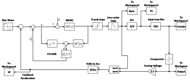
The general system block diagram of modulator is shown in Fig. 7.
Fig. 7Block diagram of ΔΣ modulator system
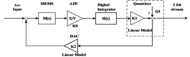
The loop is consisted of an electromechanical sensing element, a charge amplifier, a digital integrator, and a 1-bit quantizer. In Fig. 1, is the gain of AFE, is a digital integrator, is the quantizer gain, is the quantization noise of 1-bit quantizer, and is the equivalent linear model of 1-bit DAC feedback. Unfortunately, the relationship of 1-bit quantizer input and output is nonlinear, here, a quasi-linear model of the 1-bit quantizer is presented in Fig. 1, where the quantizer output is equal to the sum of quantization noise and quantizer input with a quantization gain .
The sensing element can be modeled as a mass-spring-damper system, a 2nd order dynamics with transfer function that can be expressed as Eq. (18):
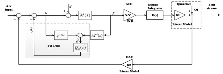
where is the proof mass, is the damping coefficient and is the spring constant. Due to the parametric yield errors, and are not always the actual values caused by manufacturing process. So, FO-DOB is employed to observe and compensate the model mismatch of the proof mass. The proposed architecture of the closed-loop modulator with a FO-DOB is given in Fig. 8.
In Fig. 8, is the inverse model of the sensing element , is the fractional-order Q-filter, is the time delay. By observation from Fig. 8, FO-DOB is employed to observe and compensate the disturbances and model mismatch of the sensing element. The effects of the employed FO-DOB are shown in the following.
Fig. 8Block diagram of the proposed ΔΣ modulator system
4. Simulation
Firstly, the Simulink model of the proposed modulator with a FO-DOB is developed shown in Fig. 9.
Fig. 9Simulink model of the proposed ΔΣ modulator with a FO-DOB
In Fig. 9, the oversampling ratio (OSR) needs to be specified in the modulator system. Here, we choose sample frequency as 128 kHz, and OSR = 64. The mechanical and system parameters in the proposed architecture of the closed-loop modulator with a FO-DOB are listed in Table 1.
Table 1Parameters of the proposed architecture
Parameter | Value |
Proof mass [mg] | 20 |
Damping coefficient [Ns/m] | 2.4×10⁻³ |
Spring constant [N/m] | 100 |
AFE gain [V/m] | 4.55×10⁷ |
Comparator gain | 1 |
Feedback gain [m/s2] | 49.05 |
External disturbance | 3.4 ng/√Hz |
Two numerical experiments of the proposed architecture have been performed in the following.
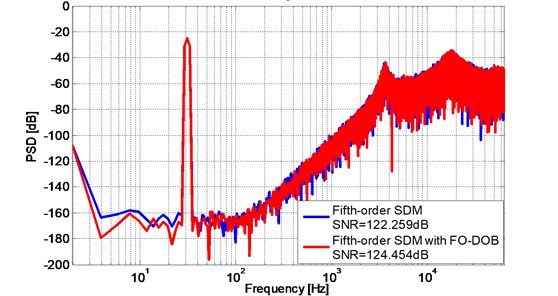
Case one. A 5th order closed-loop modulator with the FO-DOB.
In this case, we choose the digital integrator for the closed-loop modulator as follows:
Due to the system of sensing element responds quickly, in Fig. 8 is set as 0.2 ms, and has been adjusted empirically, so finally is selected as 2.4 to inspect the effects of FO-DOB.
Taking 2.4 in Eq. (14):
From Eq. (20), can be obtained. Taking , the linearized parameters , , and the major transfer function into Fig. 9, The corresponding SNR is 124.454 dB which is 2X improved comparing to 5th order modulator only. The PSD plot of the proposed modulator is shown in Fig. 10. Comparing to the only 5th order modulator, the proposed modulator with the FO-DOB not only performs better SNR, but also lower noise floor.
Fig. 10PSD of the 5th order ΔΣ modulator using FO-DOB
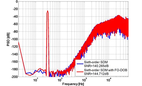
Case two. A 6th order closed-loop modulator with FO-DOB.
In this case, we choose the digital integrator for the closed-loop modulator as follows:
Taking , the linearized parameters , , and the major transfer function into Fig. 9, The corresponding SNR is 144.265 dB which is 2X improved comparing to 6th order modulator only. The PSD plot of the proposed modulator with FO-DOB is shown in Fig. 10. Comparing to the only 6th order modulator, the proposed modulator not only performs better SNR, but also lower noise floor.
Fig. 11PSD of the 6th order ΔΣ modulator using FO-DOB
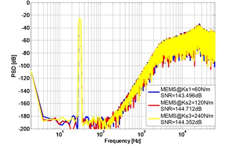
Further simulation are also observed at system response with different spring constant k and damping coefficient b, For instance, taking different spring constants 60 N/m, 120 N/m, 240 N/m in MEMS transfer function to verify the robustness of the proposed modulator with the FO-DOB, Fig. 12 and Fig. 13 show the PSD plot of the proposed 5th order and 6th order modulator with different spring constant , , using FO-DOB.
Fig. 12PSD of the 5th order ΔΣ modulator with different spring constant k
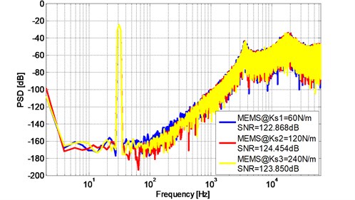
Fig. 13PSD of the 6th order ΔΣ modulator with different spring constant k
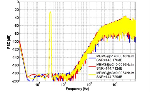
Also, taking 1.8×10⁻³Ns/m, 3.6×10⁻³Ns/m, 5.4×10⁻³Ns/m in MEMS transfer function, Fig. 13 and Fig. 14 show the PSD plot of the proposed 5th order and 6th order modulator with different damping coefficient .
Simulation results show that SNR and the noise floor of the three sensing elements with different and three sensing elements with different only present an acceptable slight fluctuation which indicate that the proposed modulator using FO-DOB has strong robustness against to the sensitivity of MEMS devices.
Fig. 14PSD of the 5th order ΔΣ modulator with different damping coefficient b
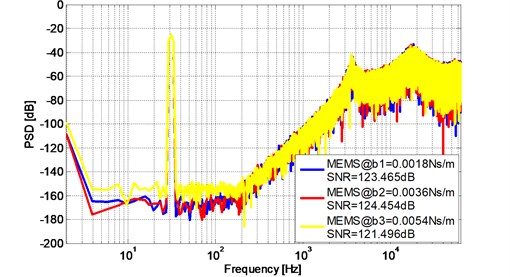
Fig. 15PSD of the 6th order ΔΣ modulator with different damping coefficient b
5. Conclusions
A novel design of a high order closed-loop Sigma-Delta modulator using a fractional-order disturbance observer is present in this paper. The proposed 5th order Sigma-Delta modulator using FO-DOB achieved SNR = 124.454 dB in simulation and noise floor under –170 dB in frequency of [5-150Hz] and the proposed 6th order Sigma-Delta modulator using FO-DOB achieved SNR = 144.712 dB in simulation and noise floor under –190 dB in frequency of [5-150 Hz]. The numerical experiments also show the improved robust stability of the proposed Sigma-Delta modulator using fractional-order disturbance observer comparing to the pure 5th order and 6th order Sigma-Delta modulator. This study can promote the development of high performance of MEMS accelerometer, also provide a scientific and technical supports for the application of fractional-order disturbance observer.
References
-
Marek J. MEMS for automotive and consumer electronics. IEEE International on Solid-State Circuits Conference Digest of Technical Papers, 2010.
-
Aysu A., Ghalaty N. F., Franklin Z., Yali M. P., Schaumont P. Digital fingerprints for low-cost platforms using MEMS sensors. Proceedings of the Workshop on Embedded Systems Security, New York, 2013.
-
Lin H., Zhang Y., Long F., Mei F., Yu M., Lin F., Yao L., Jiang X. Digital noise-coupling technique for delta-sigma modulators with segmented quantization. IEEE Transactions on Circuits and Systems II: Express Briefs, Vol. 61, Issue 6, 2014, p. 403-407.
-
Bafandeh A., Yavari M. Digital calibration of amplifier finite DC gain and gain bandwidth in mash ΣΔ modulators. IEEE Transactions on Circuits and Systems II: Express Briefs, Vol. 63, Issue 4, 2016, p. 321-325.
-
Luo X. C., Feng J. A monolithic MEMS gyroscope interface circuit in 0.35 μm CMOS. Tien Tzu Hsueh Pao/Acta Electronica Sinica, Vol. 42, Issue 9, 2014, p. 1868-1872.
-
Keller M., Buhmann A., Ortmanns M., Manoli Y. A method for the discrete-time simulation of continuous-time sigma-delta modulators. IEEE International Symposium on Circuits and Systems, 2007, p. 241-244.
-
Saxena G. D., Thamarai V. Modeling and simulation of high performance sixth order sigma-delta MEMS accelerometer. International Conference on Computational Intelligence and Communication Networks, 527, p. 531-2011.
-
Petkov V. P., Boser B. High-order electromechanical modulation in micro-machined inertial sensors. IEEE Transactions Circuits and Systems, Vol. 53, Issue 5, 2006, p. 1016-1022.
-
Handtmann M., Aigner R., Meckes A., Wachutka G. Sensitivity enhancement of mems inertial sensors using negative springs and active control. Sensors and Actuators A, Vol. 97-98, 2002, p. 153-160.
-
Plekhanov S., Shkolnikov I. A., Shtessel Y. B. High order sigma-delta modulator design via sliding mode control. American Control Conference, 2003, p. 897-902.
-
Yu S. H. Analysis and design of sigma-delta modulators using the theory of sliding modes. International Conference on Signals and Electronic System, Poznan, Poland, 2004, p. 91-94.
-
Colmet E., Juillard J., Guessab S. Resolution enhancement of a sigma-delta micro-accelerometer using signal prediction. International Conference on MEMS, NANO and Smart Systems, Banff, Canada, 2004, p. 72-79.
-
Chen Y. Q., Vinagre B. M., Podlubny I. Fractional order disturbance observer for robust vibration suppression. Nonlinear Dynamics, Vol. 38, 2004, p. 355-367.
-
Kempf C. J., Kobayashi S. Disturbance observer and feedforward design for a high-speed direct-drive positioning table. IEEE Transactions on Control System and Technology, Vol. 7, Issue 5, 1999, p. 513-526.
-
Brahima N. I., Darouach Voos M. H., Michel Z. Design of unknown input fractional-order observers for fractional-order systems. International Journal of Applied Mathematics and Computer Science, Vol. 23, Issue 3, 2013, p. 491-500.
-
Liu J. K. Advance PID Control and MATLAB Simulation. Publishing House of Electronics Industry, Beijing, China, 2003.
-
Chen H., Chen Y. Fractional-order generalized principle of self-support in control system design. Journal of Automatica Sinica, Vol. 3, Issue 4, 2016, p. 430-441.
About this article

This work was supported by the research fund to the top scientific and technological innovation team from Beijing University of Chemical Technology (No. buctylkjcx06).
