Abstract
. The possibilities of changing the dynamic state of mechanical oscillatory systems are considered on the basis of using additional connections that are implemented by introducing lever mechanisms. Through the example of the problem of the dynamics of a solid body with two degrees of freedom and elastic supports, it is shown that the kinematic impact on the side of the bearing surface can be greatly reduced by a deliberate displacement of the concentrated masses on the elements of the lever device. The method for developing mathematical models is proposed. The results of the experiment are presented.
1. Introduction
The problems of the dynamics of transport and production machines are diverse and their solution is essential for improving the reliability of operation in conditions of intense vibration loading. The search for methods and means for the dynamic state management, as well as their development, is typical for railway transport, construction and road machines, and the operation of vibrational technological equipment, which is reflected in the work of recent years [1-3].
External excitations in technical objects are of different nature. Among other things, they can be force, that is, to be applied directly to the mass inertia elements, and also kinematic, when the excitation is transmitted through a vibrating supporting surface or base.
The methodological bases for solving applied technical problems are presented in [4-6]. The possibilities of using mechanical oscillatory systems in structures that are used as computational models for technical objects can be expanded by introducing various additional connections, including various mechanisms [7] and motion transformation devices.
The proposed work deals with the development of new approaches in the problems of changing the dynamic states of technical objects on the basis of the idea of controlling the properties of systems using special mechanisms.
2. The main idea of the approach: constructive forms and principles of obtaining dynamic effects
A peculiar aspect of the considered approach is the possibility of providing simultaneous dynamic damping in two coordinates of a technical object. This effect is implemented by a mechanical system that transforms the vibrations of the supporting surface.
The device for changing the dynamic state of the object is installed on elastic supports in the form of springs. It includes lever mechanisms for motion transformation, which are installed on each of the supports of the protection object. In their turn, the mechanisms have additional balanced weights at their free ends, which have the capabilities of controlled displacement to allow for the certain values of the so-called “blocking” frequency of the external force on two supports. This provides a mode for the dynamic damping of the vibrations of the protection object simultaneously in two coordinates.
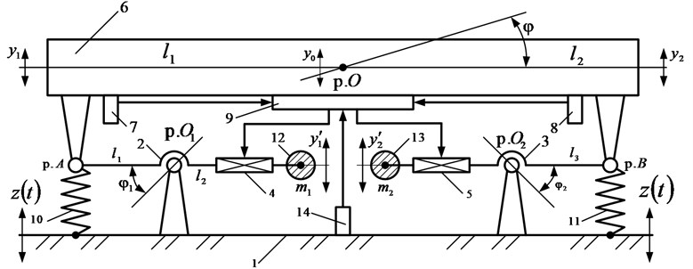
The device has vibration measuring means (sensors for measuring the motion parameters of the protection object and the base) and information processing units, as well as power sources and servo drives (in the form of screw mechanisms). Fig. 1 shows a schematic diagram of an object with a system of dynamic damping of vibrations excited by vibrations of the bearing surface.
Fig. 1Schematic diagram of the vibration protection system. The following designations are accepted: base 1; levers 2, 3; servo drives 4, 5; protection object 6; vibration measuring sensors 7, 8; control unit 9; springs 10, 11; loads 12, 13; vibration sensor of the base 14

The following designations are also used for the study: are oscillations of the center of gravity of the protection object 6; , are coordinates of vertical oscillations of the protection object 6; , are mass inertial parameters of the protection object 6; are angular oscillations of the protection object 1; are angular oscillations of the lever 2; is angular oscillations of the lever 3; - are the lengths of the arms of levers 2 and 3; , are additional loads 12 and 13; are fluctuations of the load 12; is fluctuations of load 13; is the kinematic perturbation of the base 1; point is the center of gravity of the object of protection 6; point is a point of rotation of the lever 2; point is a point of rotation of the lever 3; point is a point of attachment of the lever 2 and the spring 10 with the object of protection 6; point is a point of attachment of the lever 3 and the spring 11 with the object of protection 6. The functioning of the system is ensured by the sequence of actions of the elements; the system has mass inertial and elastic bonds. The motion of the levers is regulated by the control unit and servo drives. The operating mode of the vibration protection system is regulated by means of vibration measuring sensors and the control unit.
Adaptation of the system is carried out by means of a device that works as follows: from the base 1 to the protection object 6, a kinematic perturbation is transmitted through the springs 10, 11. Information on the value of the oscillations of the protection object 6 is recorded by the sensors 7 and 8 and enters the control unit 9, programmed to zero out the amplitudes of the vibrations of the protection object 6.
The control unit 9 implements the adaptation algorithm; the signal is applied to servo drives 4 and 5 to change the length of the arms of levers 2 and 3, during the angular motions of which the loads 12 and 13 create additional inertial forces to compensate for the vibrations of the protection object 6. The value of the kinematic excitation frequency at which the amplitudes of the vibrations of the protection object 6 become equal or differ among themselves within the specified limits.
3. Construction of a mathematical model of the system
The mathematical model of the system is based on the approaches outlined in [3, 5] and presupposes the preliminary compilation of system expressions for kinetic and potential energy; it is assumed that the system performs small oscillations with respect to the static equilibrium position and possesses linear properties. In Fig. 2, as a result of preliminary actions, a structural mathematical model is presented (the structural diagram of the dynamically equivalent automatic control system [3, 5]).
Fig. 2Structural mathematical model of the technical object in Fig. 1

On the basis of the above structural diagram, it is possible to obtain transfer functions for an external kinematic excitation :
where
In the notation , , , , is the mass of the protection object, is the moment of inertia of the solid body relative to the center of gravity; , , , , ; ,, - are geometric parameters of the system, which are shown in the schematic diagram (Fig. 1).
In Eq. (1) and (2), is a complex variable, the symbol < – > corresponds to the image of the variable by Laplace [3, 5].
It follows from Eqs. (1) and (2) that if fulfilling the condition:
external impact on points (1) and (2) are “blocked” and the values of the coordinates and simultaneously assume zero values, which predetermines the physical effect of simultaneous dynamic damping of vibrations in two coordinates.
4. Discussion of the results
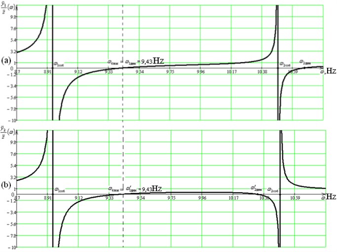
Fig. 3 shows the amplitude-frequency characteristics of the system, reflecting the specific aspects of the dynamic state of the object with simultaneous dynamic damping of vibrations along two coordinates: , .
The analysis of the obtained data makes it possible to note the presence of dynamic effects, which involve the possibilities of a significant change in the dynamic properties of the system with respect to damping of vibration effects. Amplitude-frequency characteristics were obtained on the basis of computational modeling for a mechanical system with the following parameters: 20 kg; 20 kg·m2; 8000 N/m; 10000 N/m; 15 kg; 10 kg; 1 m; 2 m; 1,85 m; 0,64 m. Based on the studies carried out, diagrams of dependency of and vibration amplitudes on the frequency of the kinematic excitation were plotted, according to the results of which it was found that at a frequency 9.43 Hz there is a mode of simultaneous “blocking” of the motion along two coordinates, which confirms the correspondence of the set goal to the calculations obtained.
Fig. 3Amplitude-frequency characteristics of the system according to Fig. 1

5. Conclusions
Technical objects considered as mechanical oscillatory systems with several degrees of freedom can have specific dynamic states, including, and modes of dynamic damping of oscillations simultaneously in two coordinates. Effects can be achieved using additional input devices for the conversion of motion, in particular, based on lever mechanisms. The capabilities of the system are significantly extended when using the automatic parameter setting system.
References
-
de Silva C. W. Vibration. Fundamentals and Practice. CRC Press, Boca Raton, London, New York, Washington, 2000, p. 957.
-
Karnovsky I. A., Lebed E. Theory of Vibration Protection. Springer International Publishing, Switzerland, 2016, p. 708.
-
Eliseev S. V., Artyunin A. I. Applied Theory of Oscillations in Problems of the Dynamics of Linear Mechanical Systems. Nauka, Novosibirsk, 2016, p. 459, (in Russian).
-
Frolov K. V., Furman F. A. Applied Theory of Vibration Protection Systems. Mechanical Engineering Publ., Moscow, 1985, p. 286. (in Russian).
-
Eliseev S. V., Reznik Yu. N., Khomenko A. P., Zasyadko A. A. Dynamic Synthesis in Generalized Problems of Vibration Protection and Vibration Isolation of Technical Objects. Irkutsk State University, Irkutsk, 2008, p. 523, (in Russian).
-
Harris С. М., Сrеdе C. E. Shock and Vibration Handbook. McGraw-Hill Book Со, New York, 2002, p. 1457.
-
Eliseev S. V., Lukyanov A. V., Reznik Yu. N., Khomenko A. P. Dynamics of Mechanical Systems with Additional Ties. Irkutsk State University, Irkutsk, 2006, p. 316.
