Abstract
The paper demonstrates modelling and analysis of the thin circular plate. Numerical and analytical methods were used to analyse the problem. The introduction is about the vibrations of thin circular plate made from steel. Boundary conditions and constitutive equation on dynamics of the plate were shown. Moreover, the model of vibrations of the thin plate was presented. Next part shows the concept of test stand. It is based on Bruel & Kjer impedance tube, Polytec laser vibrometer and white noise generator. The research of thin steel plates was done. The eigenfrequencies and modes of vibrations were found using theoretical and experimental methods. Moreover, comparison between obtained results was shown. Last but one chapter presents the influence of support stiffness on vibrations spectra. Abstract model was used to explain the difference between experimental and theoretical results. The summary of the whole paper includes discussion on the obtained results and synthetic conclusions about vibrations of the considered system. Conclusions also show further application of this investigation.
1. Introduction
Using dynamic models is common in machine modeling and testing. Modelling is particularly useful in cases where experimental research is very expensive or time consuming. In addition, there are many cases where, due to the nature of the work carried out, it is not possible to carry out interesting tests, for example: destructive tests of units manufactured individually [1, 2].
Therefore, it is necessary to create and identify dynamic models. For obvious reasons, it is not possible to build a model describing all phenomena in a considered system. Models have to be relevant to the phenomenon under investigation. Due to the necessity of simplification dynamic response of the model may differ from experimental data. It is very difficult to select such model parameters to ensure compability of theoretical and experimental data. The simplification of the model is mainly responsible for the discrepancy, i.e. omission of significant phenomena or errors associated with the conditions of the experiment. This article focuses on theoretical and experimental studies of thin vibrating circular plate. The purpose is to determine the conditions for identification of material parameters of thin plates made of different types of materials [3, 4, 7].
2. Dynamic model of thin circular plate vibrations
Free vibrations of circular symmetrical thin plates are described by the following equation [1, 2]:
where: – flexural rigidity, – plate deflection, – radial coordinate, – angular coordinate, – density of the steel, – nabla operator.
To solve this equation, it is necessary to formulate boundary conditions. In the case of the clamped edge they have the form [5]:
where: – radius of the plate.
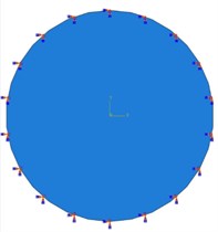
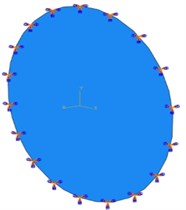
Fig. 1Clamped circular plate
The frequency of the free vibrations can be determined by solving the problem on eigenvalues [6]:
where: – thickness of the plate, , – number of the vibration mode (1, 2, 3,…; ), – roots of the characteristic equation in the dimensionless form of the subsequent modes determined numerically.
Higher values can be determined on the basis of a simplified relationship (with an error smaller than 1 %):
In this case, the calculated frequencies are 24, 50, 82, 94, 144, 209, 210, 287, 374, 474, 585, 708, 842, 988, 1147, 1316 and 1 498 Hz. The difference between next components is about 160 Hz.
3. Experiments
The tested specimen was a thin circular symmetrical 1 mm thick plate made of steel. The investigated plate was made of homogeneous material. The outer diameter was 100 mm.
Fig. 2Test stand prepared for testing – impedance tube and generator module
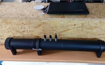
The plate was placed in an B & K 4206T impedance tube with a B & K 3160 generator module (Fig. 2). The module generated two excitation signals: white noise and harmonic signal in the frequency range 0-1000 Hz.
Fig. 3Test stand prepared for testing – laser vibrometer
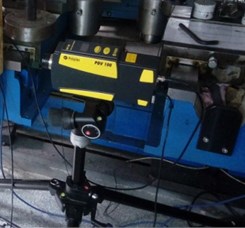
Fig. 4Scheme of the measuring system
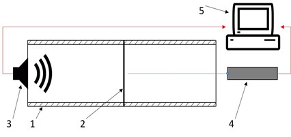
The measurement system consisted of a measuring card, a computer with a SigLab software (analyzer and data logger), a Polytec PDV-100 laser vibrometer and a B & K 3160 generator. The scheme of the test stand is shown in Fig. 4. The preliminary results are shown in the Fig. 5.
Fig. 5Spectrum of vibration velocity of the tested plate
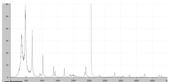
Based on the recorded vibration velocity signals, the vibration frequencies were determined. Significant spectral components are 356, 473, 691, 1014, 1346, 1696, 2343, 2772, 3225, and 3678 Hz. The difference between next harmonics is 496 Hz. Frequencies determined experimentally are not consistent with the results of theoretical calculations. The largest discrepancies are observed in the range up to 200 Hz.
4. Influence of support stiffness on eigenfrequencies
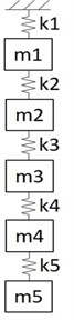
Big differences between analytical and experimental results indicate a significant impact of support stiffness on the frequency response obtained. In order to explain the phenomenon, the abstract discrete model was proposed (shown in Fig. 6).
Proposed model shows the relationship between the eigenfrequencies of two oscillating systems with countable sets of eigenvalues. The idea of simplification is replacing continuous systems with infinite number of the eigenfrequencies by discrete systems with finite sets of eigenvalues. First subsystem (consisted of and ) represents two first eigenfrequencies of the test stand. Stiffness is the stiffness of the connection between the test stand and the object under test (stiffness of the support). The values of the obtained amplitudes will not correspond with experiments because of significant simplifications used in considered model. However, it does not qualitatively affect the obtained results. It is only a model of the influence of stiffness of the connection between the test stand and the object on spectral structure of the investigated system. The advantage of this approach is that the analysis is much simplier. For computations it was assumed that:
Fig. 6Abstract model of tested plate and test stand
The characteristic equations of the considered system have the following form:
where: – stiffness matrix of the considered system, – mass matrix of the considered system.
For the purpose of determining the eigenvalues, characteristic Eq. (11) were solved. The plot shows the changes in the value of the system’s eigenvalues depending on the stiffness of the support of the plate (Fig. 7).
Fig. 7Eigenfrequencies of the tested object and test stand given by characteristic Eq. (11) – influence of stiffness of the connection between the test stand and the plate on spectral structure (support stiffness)
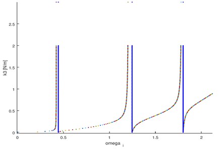
Simulations show that depending on the rigidity of the mounting, the selected vibration frequencies can change or even not occur ( 0.5), while rest of the frequencies remain unchanged (to the accuracy of the measurement error). In more complex case of continuous systems, the essence of the phenomenon remains unchanged. Only the quantitative description will change (exact values of the frequencies and the amplitudes).
5. Conclusions
The paper presents experimental and analytical investigation of the circular thin plate vibrations. The first chapter presents the problem of using models in vibration testing and machine design. The dynamics of the thin circular symmetrical plate was further described and its eigenfrequencies were determined. The third chapter presents the research stand and the results of the experiment. The next part presents an abstract model of a research station and a research object. Based on the elementary analysis (simplified case), the qualitative nature of the influence of the stiffness of the connection between test stand and plate on the spectral structure has been demonstrated.
The studies show that the dynamic parameters of the station have a significant impact on the obtained results. In the case of the dynamics of the circular plate, the stiffness of the support is a very important parameter. It means that there are two ways to carry out a thorough research. The first one is that the support conditions should be very well defined. The second one is that a series of experiments for a various support stiffness should be done and the components unrelated to the test element (as shown in Fig. 7) should be eliminated. In many cases, applying the first approach is very difficult, so the research on the second method is important and it could be used in many practical cases.
References
-
Newman M., Pipano A. Fast Modal Extraction in NASTRAN via the FEER Computer Program. NASA, TM X-2893, p. 485-506, 1973.
-
Cheng L., Nicolas J. Free Vibration Analysis of a Cylindrical Shell-Circular Plate System with General Coupling and Various Boundary Conditions. G.A.U.S., Department of Mechanical Engineering, Université de Sherbrooke, Québec, Canada J1K 2R1.
-
Jaroszewicz J., Zoryj L. M. The method of partial discretization in free vibration problems of circular plates with variable distribution of parameters. International Applied Mechanics, Vol. 42, Issue 3, 2006, p. 364-373.
-
Dąbrowski Zbigniew, Chiliński Bogumił Identification of a model of the crankshaft with a damper of torsional vibrations. Journal of Vibroengineering, Vol. 19, Issue 1, 2017, p. 539-548.
-
Chiliński Bogumił, Zawisza Maciej Analysis of bending and angular vibration of the crankshaft with a torsional vibrations damper. Journal of Vibroengineering, Vol. 18, Issue 8, 2016, p. 5353-5363.
-
Chiliński Bogumił, Pakowski Radosław, Stanik Zbigniew Coupled lateral-torsional vibrations of a symmetric rotor. Journal of Kones, Institute of Aviation, Vol. 23, Issue 4, 2016, p. 41-47.
-
Chiliński Bogumił, Dziurdź Jacek, Zawisza Maciej The analysis of the influence of a torsional vibration dmper on transversal displacement of a crankshaft. Journal of Kones, Institute of Aviation, Vol. 23, Issue 4, 2016, p. 33-39.
-
Dąbrowski Zbigniew, Chiliński Bogumił, Pankiewicz Jarosław A proposition of a torsional-bending vibrations modeling of combustion engines. Journal of Kones, Institute of Aviation, Vol. 23, Issue 4, 2016, p. 71-77.
-
Dąbrowski Zbigniew, Chiliński Bogumił Influence of torsional-bending coupling on transverse vibration of piston engine. Vibrations in Physical Systems, Vol. 27, 2016.
About this article

