Abstract
Advanced research equipment like the SOLARIS synchrotron requires specific working conditions. One of the major disturbances are vibrations of the synchrotron foundation plate, derived from internal equipment and external sources. The purpose of the present research was to identify the dominant sources and to analyze the wave propagation path. In basic research, a set of circulating pumps for cooling liquid was selected and under controlled conditions measurements were made. As a result of the analysis of the data obtained, was revealed an inability to which could affect the work of the synchrotron. The paper presents partial results and conclusions from the research conducted.
1. Introduction
The Synchrotron National Synchrotron Radiation Center is the first synchrotron in Poland. Synchrotron is a modern multidisciplinary research device that has opened up new opportunities in many areas of science such as biology, chemistry, physics, materials engineering, medicine, pharmacology, geology and crystallography. The SOLARIS Synchrotron consists of an electron source, a linear accelerator and an accumulation ring. As the source of electrons is used gun with barium oxide (BaO). Electrons are emitted from the surface of the cathode due to the phenomenon of electron thermoelectricity. The SOLARIS Synchrotron Linear Accelerator is made up of six accelerating straight sections powered by three power stations (RFU). [Injector System for Polish Synchrotron Radiation Facility “SOLARIS”].
The accumulation ring is the heart of the SOLARIS National Synchrotron Radiation Center. It is a replica of the accumulation ring built at the MAX IV Laboratory in Lund (Sweden) with a power of 1.5 GeV, 6 nmrad emittance and a circumference of 96 m. The main task of the ring is to accumulate and sustain as long as possible the circuitry of the synchrotron radiation circulating in it. VUV range and soft X.
The electron source and linear accelerator are located at –7.7 [m], while the accumulation ring at the foundation –3.5 [m]. With such extensive and extreme precision instruments, the influence on the work of the synchrotron has, among other things, temperature and paraseysmic vibrations. Accuracy of geometry assembly has a significant impact on beam collimations. Based on the experience of MAX IV Laboratory, the maximum vibration value of the foundation plate is determined, which is more related to the measurement resolution of the used registers. For the accumulation ring and the experimental hall, a displacement amplitude of 20-30 nm is assumed. This is a narrowband RMS (integrated value) for 5 Hz. The linear accelerator tunnel is much less susceptible to vibration, but never has the permissible numerical values. The most sensitive elements of the measuring system are the end stations where the examined samples (objects) are placed, and the optical elements – the mirrors. The admissible values were assumed to be identical to that of the Swedish synchrotron because the Solaris accelerator is identical to the smaller accelerator in Max IV. On the other hand, the guidelines established by the Swedish experts are the result of monitoring the vibrations of their previous synchrotrons at Max-lab for a period of 15 years.
2. Vibration sources
The sources of vibration transmitted to the synchrotron foundation plate can be divided into external sources coming from outside the Center and the vibrations emitted by synchrotron auxiliary devices. The main external sources are, among others, a fast tram in the streets Grota Roweckiego - Bobrzyńskiego, cars, trucks and buses. Internal sources are electric power sources such as motors, generators, power supplies; auxiliary machinery and equipment (fans, compressors, pumps, machine tools, internal transport equipment); Elements of NCPE installations and devices such as pipelines, flange valves, exhaust nozzles, diffusers; electrical equipment (transformers, switches, switches, contactors, resistors, capacitors); tools in workshops (saws, grinders, screwdrivers, hammers); installation of equipment in the building (elevator, overhead gantry and hoists, central heating and water and sewage installations, heating node, air conditioners, fans, compressors, pumps, vacuum pumps [1, 2].
Ancillary equipment selected for significant vibration sources includes all types of circulating pump circuits for cooling synchrotron components, HVAC systems, electrical power plants as well as moving personnel. The temperature stabilization system consists bending electromagnets, acceleration structures radio frequency cavities [3].
During the technological break it is possible to independently control individual auxiliaries, and examine the effect of their work on the mechanical stability of the foundation plate. So, the experiment was to start at the Wilo MVIE 5205-2 pump and the simultaneous measurement of vibration on the pump housing, on the floor in the vicinity of the pump and on the experimental hall of the synchrotron [4].
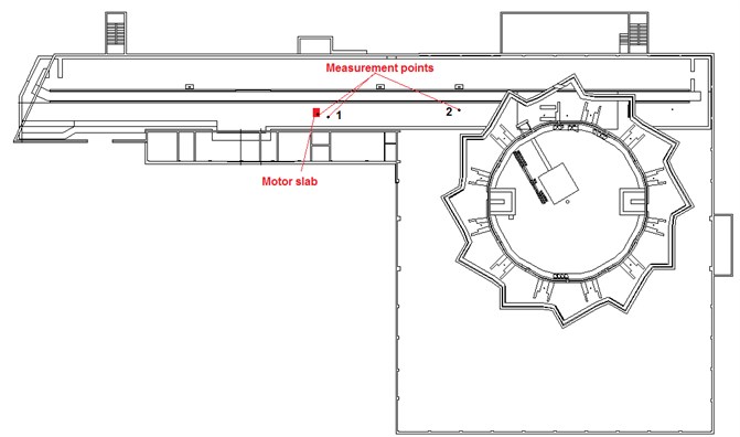
During the study two measurement sessions were conducted (Fig. 1). In the first series measurements were taken on the concrete plate to which the analyzed engine was mounted. The second measuring point was on the floor at the engine room at 3 m above ground level. The accelerator sensor was mounted about 1m from the source of vibration. This positioning of the measuring points was made in order to determine the transfer function between the motor mounting plate and the floor of the engine room [5, 6].
In the second measurement session, both the plate forming the base of the engine and the point at the level of the accumulation ring base (level –3.2 m) were measured at a distance of about 5 m from the ring walls. This location of the sensor allowed to test the vibrations transfer from the engine room to the storage ring base (Fig. 1) [7].
Fig. 1A layout of measuring sensors
3. Vibration measurements
Thanks to the control system of motors equipped with frequency inverters, it was possible to perform vibration measurements with a wide range of motor load [8].
The measuring path consisted of the following elements:
• Sensors-acceleration sensors, on a PCB356B08 motor with a sensitivity of 100 mV/g and paraseismic measurements on baseplates, type PCB393A03 with a sensitivity of 1 V/g.
• NI PIXe-1062 computer-controlled measurement system and 24bit NI-PXIe 4472B measuring card, along with IEPE (ICP) signal conditioning conditioning systems.
The location and orientation of the sensors are given in Table 1.
A 300 [s] signal was recorded for the nominal operation of the pump. RMS values for full bandwidth are listed in the Table 2.
Table 1The location and orientation of the sensors
Channel | Sensor | Location | Orientation |
Channel 0 | PCB393A03 | Ground | Horizontal |
Channel 1 | PCB356B08 X | Pump | Vertical (the transverse) |
Channel 2 | PCB356B08 Y | Pump | Vertical (the longitudinal) |
Channel 3 | PCB356B08 Z | Pump | Vertical (axially) |
Table 2RMS values for full bandwidth
Channel | Sensor | Value RMS [m/ss] |
Channel 0 | PCB393A03 | 0,0026 |
Channel 1 | PCB356B08 X | 0,0182 |
Channel 2 | PCB356B08 Y | 0,0377 |
Channel 3 | PCB356B08 Z | 0,0259 |
The next step in data analysis was to determine the power spectral density (PSD) [9]. Sample spectrum for signals measured on motor slab, machine room floor and accumulation ring base are shown below.
Fig. 2Spectrum of Y axis signal measured on the motor slab
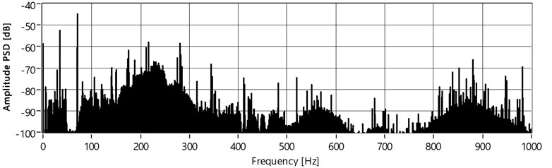
Fig. 3Spectrum of signal measured on the machine room floor
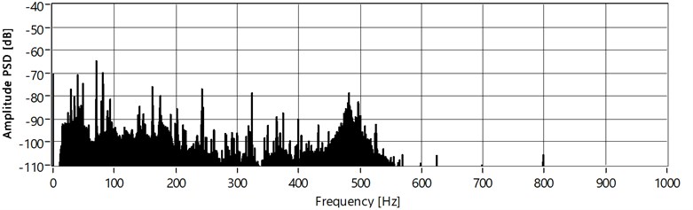
Fig. 4Spectrum of signal measured on the accumulation ring base
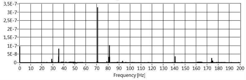
In these spectra you can recognize the rotational frequency and its second, fourth, and vane harmonic. A brief summary of these frequencies is provided in the table below.
Table 3Summary of frequencies
No | Frequency [Hz] | Source |
1 | 35 | Rotation frequency |
2 | 70,6 | II harmonic frequency |
3 | 141,2 | IV harmonic frequency |
4 | 175,4 | V harmonic frequency – blade frequency |
4. Conclusions
The analysis showed a significant amplitude of the second harmonic of the rotational frequency. This is a symptom of lack of rotation system axiality. The motor with the pump is connected by a rigid coupling, which can cause a significant increase in vibration even at very slight eccentricity.
References
-
Huang H., Kay J. Vibration measurement at diamond and the storage ring response. Proceedings of EPAC, Edinburgh, Scotland, 2006.
-
Haga K., Nakayama M., Masuda K., Ishizaki H., Kura M., Meng L., Oku Y. The vibration measurement at the photon factory storage ring building. Proceedings of EPAC, Vienna, Austria, 2000.
-
Nakayama Y., Ito T., Sugahara R., Takeda S., Yamaoka H., Yoshioka M., Matsui S., Zhang C., Yamashita S. Characteristics of ground motion at kek and sprong-8. Proceedings of EPAC, Lucerne, Switzerland, 2004.
-
Sarkar S., Ilhoff E., Sibley C., Soong S. B., Wells S., Tsentalovich E., Zwart T., Shaw J. Vibration measurement for instrumentation and diagnostics. Particle Accelerator Conference, Vol. 2, 1997, p. 2241-2243, https://doi.org/10.1109/PAC.1997.751169.
-
Simos N., Fallier M., Amick H. Comparative study of vibration stability at operating light source facilities and lessons learned in achievinh nsls II stability goals. 11th European Particle Accelerator Conference, 2008.
-
Sharma S., Doom L., Jain A., Joshi P., Lincoln F., Ravindranath V. Optimization of magnet stability and alignment for nsls II. Conference Proceedings, C110328, 2011, p. 2082-2086.
-
Sensitivity analysis to variation in input soil parameters. MaxLab IV vibrationer, Raport.
-
Korbiel T., Krzyworzeka P. An application of splines in synchronous analysis of nonstationary machine run. Diagnostyka, Vol. 4, Issue 44, 2007, p. 119-124.
-
Zieliński T. Cyfrowe przetwarzanie sygnałów. Od teorii do zastosowań (Digital Signal Processing. from Theory to Applications). Wydawnictwa Komunikacji i Łączności WKŁ, 2014, (in Polish).
About this article

