Abstract
The intensive development of gas transport and compressor manufacturing aimed at increasing the unit capacities of gas pumping units, creating high-flow centrifugal compressors, increasing the productivity of compressor shops has led to the appearance of fundamentally new problems in the diagnosis of industrial pipelines. The reasons for premature failure of piping manifold of gas pumping stations can be associated with both high static voltage in the pipelines and a high level of vibration. The main reasons for the increased vibration of the technological pipelines of the centrifugal compressor can be significant disturbing forces of the gas flow, coincidence of the natural frequencies of the pipeline system elements with frequencies of the disturbing forces, low dynamic stiffness of the pipeline- support system or a combination of the above conditions. The most effective method for studying problems such as low-frequency vibrations is the combination of engineering means for calculating dynamic processes and the results of measurements of the parameters of these processes in real systems and operating modes of the compressor stations. The hypotheses of the occurrence of low-frequency vibrations in pipelines are considered during the study, the acoustic properties of the process piping, and the resonant vibrations conditions are calculated. A computer model was created in the ANSYS Workbench software in order to consider the loading conditions for process piping. Based on Gazprom company standard 2-2.3-324-2009, an algorithm is proposed that is of practical importance for engineers of plant diagnostics operating gas transmission equipment. It is proposed to combine the performance of vibroacoustic studies and computing modeling with the determination of trends in the technical condition of the system for the analysis of changes in vibro-parameters. As a result of the work, direct measurements of the vibrodiagnostic specialists of the operating compressor station were compared with the obtained modeling data. Some methods were proposed to reduce the impact of operating conditions and design of the process piping on unacceptable low-frequency vibrations.
Highlights
- The research shows an influence of heterogeneity of the gas flow in the gas compressor unit manifold on the appearance of abnormal oscillations.
- This technique allows specialists determine the areas where there is an influence of the flows gas dynamics on the increased vibration of the piping from the heterogeneity of the geometry point of view; determine the dependence of the influence intensity of flow; help to increase the reliability of the gas compressor units.
- As a result of the work there were given recommendations for improving the efficiency and reliability of the compressor station to reduce the likelihood of vibrations in dead ends.
1. Introduction
Research Objective: the development of a methodology using computer modeling to determine the causes of additional loading of the compressor station pipeline systems and cracking, including gas-dynamic, static and modal analyzes of the compressor station operating modes. It is also important to take into account the self-excited vibrations of the working fluid to determine the effect of gas-dynamic parameters on the resonant vibration of the individual compressor shops piping assemblies [1]. A method of comparing statistical studies and field tests in the form of monitoring vibration parameters in order to identify the regular dependence of resonance and its relationship with the spectral characteristics of drive units was applied in this study.
The intensive development of gas transport and compressor manufacturing aimed at increasing the unit capacities of gas pumping units, creating high-flow centrifugal compressors, increasing the productivity of compressor shops has led to the appearance of fundamentally new problems in the diagnosis of industrial pipelines. On the one hand, these problems were caused by the design features of compressor shops with high-flow blower: large diameter of the process piping; ring collecting mains; a support system is fundamentally different from process piping of piston gas compressor units. On the other hand, new physical phenomena have appeared in the gas-dynamic and mechanical piping systems: high frequencies of gas flow disturbances; the possibility of radial gas-dynamic resonances; self-excited vibrations of the gas flow in the region of both low and high frequencies; high flow turbulization; dynamic deformation of the pipe jacket shape [2].
The main distinguishing feature of compressor station process piping as an object of diagnosis is that these systems, when interacting with complex variable-permanent loads, are systems with distributed parameters. This circumstance determines the fundamental impossibility of diagnosing the causes of a state change only by experimental means that allow obtaining diagnostic information at discrete points of the system. Therefore, for the effective diagnosis of such systems it is necessary to combine direct measurements with the creation of mathematical models and disturbance models, which will allow taking into account most of the factors affecting the object.
The object of the study is compressor station (CS) process piping – CS-19A, owned by LLC Gazprom Transgaz Ufa. A survey of process piping revealed a change in elevations, which may be related to the deformation of pipelines due to the complex effect of destructive factors. Such deformations can lead to high stress levels when the design position of the support’s changes. In this regard, the analysis of the stressed-deformed state of process piping for gas compressor units was carried out.
Measurements of vibration of process piping showed that their level exceeds acceptable standards.
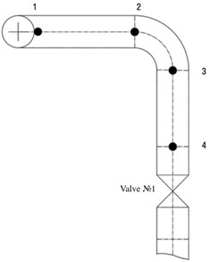
According to the results of leveling of gas compressor unit process piping No. 31, No. 33 of compressor station – CS-19A, it was established that there are slope excesses. The dynamics of changes are shown on Fig. 1 and 2.
Fig. 1Layout of pick-up points
Vibration rates for gas compressor unit process piping according to [3]:
– admissible values: up to 11.2 mm/s;
– requires measures: from 11.2 to 18 mm/s;
– inadmissible: over 18 mm/s.
Table 1 shows the values of vibration velocity, indicating points with excess admissible values.
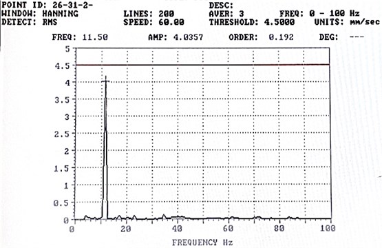
An analysis of the spectra found that the frequency of the dominant vibration component at the stabbing valve No.1 of gas compressor units No. 31-34 is equal to 11.5 Hz. Fig. 2 shows one of the spectral results of vibration measurements, on which you can notice an inadmissible value of the vibration frequency.
In this work, we calculated the low frequency “dead-end” vibrations from the conditions of their occurrence [3]:
– the gas velocity in the manifold tee-joint at the dead end should be greater than the critical velocity ;
– the presence of at least two dead ends connected to one manifold block with a ratio of dead-end lengths close to odd: 1.35;
– the ratio of the distance between the connections of the dead ends with the manifold block along the axis of the manifold block to the average length is close to even (0, 2, 4).
Table 1Measured values of vibration velocity in mm/s
No. gas compressor unit | Measuring direction | Control point No. | |||
1 | 2 | 3 | 4 | ||
31 (reserve) | Upright | 4,25 | 1,22 | 0,13 | 1,11 |
Horizontal | 12,22 | 4,10 | 0,11 | 2,59 | |
Axial | – | 16,87 | 0,12 | 16,33 | |
33 (reserve) | Upright | 2,06 | 1,58 | 3,49 | 2,45 |
Horizontal | 11,07 | 2,01 | 2,79 | 2,48 | |
Axial | – | 17,36 | 2,24 | 2,40 | |
Note: bold font indicates values that exceed the standard | |||||
Fig. 2Spectrum of the reference measurement point in front of the stabbing valve No. 1 of gas compressor unit No. 31 (in reserve)
The processes described in this paper are considered from the point of view of a group hypothesis about the sources of resonance vibrations:
– flow turbulence. This mechanism determines a continuous spectrum of vibrations in a wide frequency range due to the friction of the gas flow on the pipe wall;
– turbulence in local inhomogeneities. This mechanism is due to the disruption of the vortices at the places where the local resistance flows around it; it is characterized by vibration frequencies in narrower (octave) frequency bands defined by the central frequency (Strouhal frequency) [4];
– self-excited vibrations in the acoustic system of the pipeline. This mechanism is based on resonance phenomena in the gas dynamic system of the pipeline, which is an amplifier of flow vibrations at frequencies characterizing it (natural frequencies).
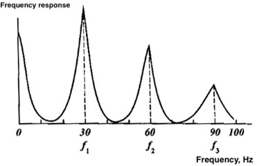
In order to determine the natural frequency of the system, which is in the frequency region of turbulization, one of a number of engineering relationships is used, which allows us to identify which of the elements can initiate non-standard vibrations. An element of type “open end – closed end” [5]. In process piping elements of this type, for example, closed bypass lines, closed suction and discharge lines of non-running units, and manhole, resonant gas vibrations can occur at frequencies determined by an odd number of quarters of pressure waves equal to the equivalent length of the element (Fig. 3 and 4). Elements of this type are the most common initiators of gas self-excited vibrations in the compressor station process piping with a high-power centrifugal compressor.
Fig. 3The scheme of the formation of standing waves at a quarter-wave
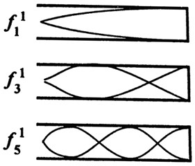
Fig. 4frequency response at a quarter-wave resonance
2. Modeling the pumping process in ANSYS
The most appropriate method for a deeper study of problems such as low-frequency vibrations is the combination of engineering tools for calculating dynamic processes and the measurement results of the parameters of these processes in real schemes and operating modes of the compressor station.
Evaluation of vibration parameters of process piping was performed by the method of computational modeling in the Ansys Workbench software with sequential use of modules for the following types of analysis:
– gas-dynamic CFX, designed for three-dimensional computational modeling of gas flows, which allows you to get the values of environmental parameters such as speed, pressure, temperature, etc. at each point of the object of study, taking into account the turbulent flow parameter and geometric features of the piping [5];
– static structural, designed to determine displacements, deformations, stresses and internal forces arising in the process piping under the influence of static loads (internal pressure);
– modal, designed to determine the vibrational characteristics of the process piping model under the influence of static loads (natural frequencies of vibrations of a prestressed structure).
The process piping of the centrifugal compressors is a piping system with branches, tees and stop valves (Fig. 6). It was also assumed that the centrifugal compressor is a sufficiently rigid and well-fixed structural element, therefore, the suction section of the piping was modeled independently. An equivalent securing that corresponds to the dimensions of the adjustable support was established for the most accurate modeling along the length of the suction manifold. The development of the model was carried out on the basis of design documentation and taking into account the individual dimensions and location of the supports (Fig. 5).
Fig. 5The geometry of the model and the layout of control points

2.1. Analysis of gas-dynamic calculation (CFX module)
3D numerical simulation of gas flow in CFX module makes it possible to obtain the magnitude of gas-dynamic parameters, such as velocity, pressure, temperature, etc., at each point of the research object, taking into account the turbulent flow parameter and geometric features of the piping system. Experimental gas-dynamic parameters of the operating mode was used for calculating CFX module (Table 2).
Table 2The operating mode of compressor station
No. Pumping unit | Mode | Inlet gas paraments | Outlet gas paraments |
31 | In reserve | 24.05.16 5,384 MPa, 296,15 K | 24.05.16 6,404 MPa, 312,15 K |
32 | In process | ||
33 | In reserve | ||
34 | In process |
Based on the results of computational modeling, the following parameters were determined:
– gas pressure at predetermined control points (Fig. 6, 8);
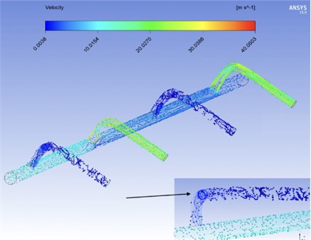
– gas velocity in the given control sections and the structure of the gas stream (Fig. 7).
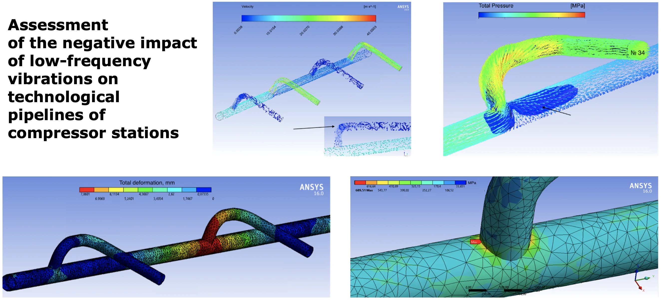
By the nature of the changes in the streamlines in Fig. 7, one can clearly visualize how the retention of gas molecules in blind, non-flow areas occurs. Also, it is possible to notice zones of gas flow disruption and, as a result, turbulence in complex heterogeneous regions such as tees and quarter-turns.
Fig. 6Pressure distribution field along the length of the piping
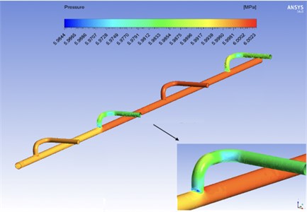
Fig. 7Gas flow line. Velocity distribution
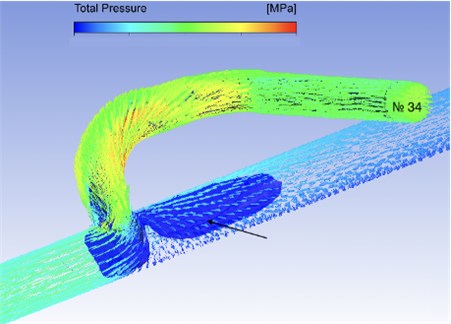
According to the results of computational modeling of the process of gas outflow from the intake manifold to the gas compressor unit, it was established that the gas flow within the working tees has a rather complex structure, characterized by a low pressure zone and a change in the direction of flow velocity.
Fig. 8The pressure distribution field in front of the entrance to a running gas compressor unit No. 34
2.2. Analysis of static calculation (static structural module)
Pressure loads from the previous hydrodynamic module acted as loads on the shell made of 09G2S steel (Russian National Standard). The appearance of the solid-state model is shown in Fig. 9. At this stage of the calculation, stresses and strains in the piping are determined due to the influence of the gas flow pressure in the pipeline sections.
The solid-state model securing scheme was used by installing adjustable supports corresponding to the geometric characteristics along the length of the intake manifold and at the inlet sections of the centrifugal compressor in front of stabbing valve No. 1.
Fig. 9Simulation of underground anchorages and supports under the stabbing valve No. 1
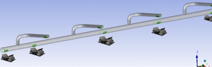
Fig. 10 shows a relatively uniform stress distribution excluding the weld joint zone of the tees. Tee joints during operation remain the most tense and, as a result, potentially dangerous.
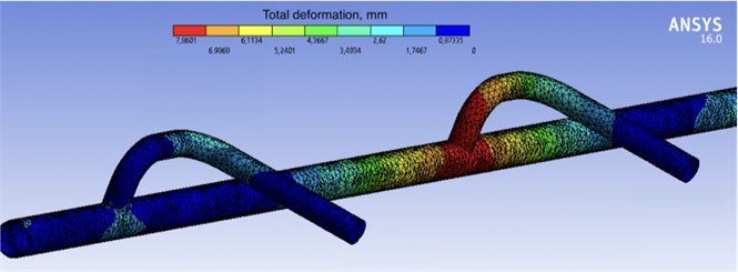
As can be seen from Fig. 11, there are zones of increased deformation, which indicates a change in the design geodetic position described as a result of the inspection of the piping.
Fig. 10Tee zone with a maximum stress value (gas compressor unit No. 33)
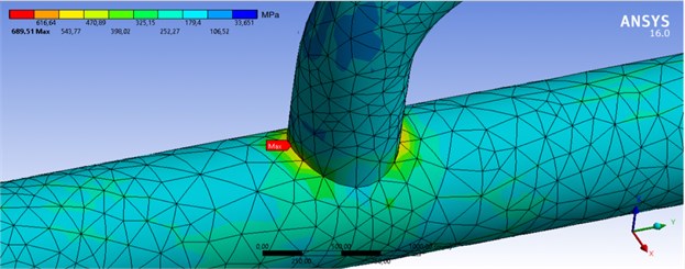
Fig. 11Deformation distribution gradient
According to the results of evaluating the parameters of the stress-strain state of the gas reduction line elements under the influence of static loads, the following was established:
– the level of equivalent stresses of the piping is from 33.7 to 689.5 MPa;
– maximum equivalent stresses (689.5 MPa) were recorded in the tee at the entrance to the gas compressor unit No. 33, which is in reserve. This fact indicates the initiation of fatigue cracks;
– the range of pipeline strains varies from 0 to 7.81 mm;
– the tee at the entrance to the working gas compressor unit No. 32 experiences maximum deformation.
The calculation showed that the process piping on the suction line and branches have a safety margin. The equivalent stresses of the pipeline walls for 09G2S steel (Russian National Standard) were 2 times lower than the tensile strength (420 MPa). However, an excess of the tensile strength of the material was recorded in the areas of tee joints, which indicates the possibility of destruction of the material [6].
2.3. Analysis of modal calculation
Modal analysis is a calculation tool for finding the natural frequencies and vibration modes of a structure (Fig. 12 and Table 3). It also represents an important component of any dynamic analysis, which allows to evaluate the dynamic behavior of a structure.
At this stage of the calculation, the parameters of the stress-strain state of the model determined during the second stage of the calculation of the problem were taken into account.
Fig. 12The obtained values of the natural frequencies of the system depending on the form of vibration
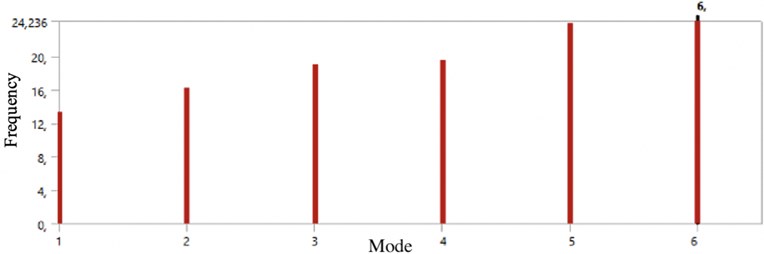
When comparing the actual value of the first harmonic 11,5 Hz, measured by vibration diagnostics specialists at the compressor station – CS-19A and the natural frequency of the piping for the first mode of vibration, the measurement error was 16.2 %. The modeling of gas pumping can be considered close to real conditions.
Table 3The results of the modal calculation for the natural frequency of process piping
Mode of vibration | Natural frequency , Hz |
1 | 13,383 |
2 | 16,295 |
3 | 19,076 |
4 | 19,484 |
5 | 23,964 |
6 | 24,236 |
2.4. Recommendations for eliminating the occurrence of self-excited vibrations
To eliminate the excess of pitches at the inlet pipelines of gas compressor units No. 31, 33, it is necessary to perform high-altitude adjustment of the stabbing valve supports No. 1.
To eliminate the conditions for the occurrence of resonant acoustic “dead end” vibrations and, as a result, increased vibration of the inlet pipelines of non-running gas compressor units, it is proposed [7-9]:
– if the gas flow when moving through the compressor station CS-19A is close to the nominal, then select operating modes with the loading of gas compressor units No. 31, 33;
– to change the position of the inlet pipelines tees of the gas compressor unit on the intake manifold in order to eliminate the conditions of acoustic resonance;
– to change the position of the valves No. 1 on the input lines of the gas compressor unit No. 31, 32, 33, 34 in order to eliminate the conditions of acoustic resonance, moving the valve No. 1 closer to the intake manifold by 1.5-2.0 m.
3. Conclusions
In order to achieve the objective, the following data were obtained:
1. The results of vibration studies of the resonant loading of the compressor station process piping.
2. The results of numerical studies of the influence of irregularities in the geometry and operating conditions of the compressor station on resonant vibration.
3. The influence of heterogeneity of the gas flow in the gas compressor unit manifold on the appearance of abnormal oscillations.
4. Recommendations for improving the efficiency and reliability of the compressor station to reduce the likelihood of vibrations in dead ends.
This technique allows specialists:
– determine the areas where there is an influence of the flows gas dynamics on the increased vibration of the piping from the heterogeneity of the geometry point of view;
– determine the dependence of the influence intensity of flow vibrations on the vibration level of the gas compressor unit assemblies in the selected frequency ranges using vibration diagnostics;
– make technical decisions to reduce these influences, helping to increase the reliability of the gas compressor;
– get a working model that allows you to explore the self-excited vibrations of the gas stream: to calculate the approximate values of the system natural frequencies and establish the most dangerous areas where cracking is possible.
It should be noted that the objective of further research will be direct modeling of recommendations to reduce the likelihood of this negative phenomenon in compressor stations. The resulting model can be used to calculate possible compressor shop operating modes (combinations of switching on and off the gas compressor unit) and selecting the optimal ones. It is also planned to check the effectiveness of the stabbing valves No. 1 displacement in order to change the ratio of the lengths of dead ends. In the future it will be possible to assess the effectiveness of these methods on the working model obtained in the course of this work.
References
-
A. M. Shammazov, Fundamentals of Technical Diagnostics of Pipeline Oil and Gas Systems, St. Petersburg: Nedra, 2009, (in Russian).
-
V. A. Yakubovich, Vibration Diagnostics of Pipelines of Compressor Stations, Moscow: Nedra-Business Center, 2004, (in Russian).
-
Gazprom company standard 2-2.3-324-2009. Diagnostic vibration inspection of technological pipelines of compressor shops with centrifugal compressor. Evaluation standards and methods of work. Moscow, LLC Gazprom Expo publ., 2009, (in Russian).
-
D. S. Butusov, Research of a Flow Pulsation in Technological Pipelines of Compressor Stations of the Main Gas Pipelines, Ph.D. Thesis, Moscow, 2000, (in Russian).
-
I. A. Belov, Modeling of Turbulent Flows, St. Petersburg, Russia: Publishing House of the Baltic State Technical University, 2000, (in Russian).
-
State Standart 32388-2013. Technological pipelines. Standards and methods for calculating strength, vibration and technological impact. Moscow: Standartinform publ., 2013, (in Russian).
-
A. N. Kozachenko, Operation of Compressor Stations of Gas Pipelines, Moscow: Oil and gas, 1999, (in Russian).
-
Gazprom company standard 2-3.5-454-2010. Rules for the operation of gas pipelines. Moscow, LLC Gazprom Expo publ., 2010, (in Russian).
-
A. V. Ustyuzhanin, “The use of acoustic analysis to study the excitability of dead ends in the piping of compressor stations,” Gas industry, Vol. 1, pp. 42-49, 2018.
About this article

