Abstract
This paper presents a thorough overview of hydraulic stimulation techniques, conducted in laboratories. It further analyses field experiments and ongoing projects for geothermal energy production to investigate if the findings from the lab can be practically applied to the field. Stimulation techniques have been long used in the oil and gas industry as a means to increasing the rock permeability and consequently the reservoir’s fluid production rate. Among the different stimulation methods, hydraulic fracturing is known to be the most successful in creating new passageways in the formation. Nevertheless, the benefits of fracturing have been hindered by the handful of events in which poor planning had led to severe seismic activities. Therefore, across the globe, many efforts were dedicated to characterizing fracture creation and propagation in different rocks, not only to provide know-how for further and safer developments in the oil and gas front but also to adapt such findings to the ever-emerging field of geothermal energy recovery. In the course of this work, over 100 papers were studied. The papers included laboratory experiments on various rock types encountered in reservoirs, where parameters such as stress regime, fracture initiation pressure, formation breakdown pressure, volume, and types of fluid injected were monitored. To investigate whether or not such practices had been previously applied in geothermal energy production, a thorough study was also conducted on large-scale experimental setups constructed in the field as well as hydraulic fracturing procedures performed in operational projects, going back as far as a decade. The results show an agreement between laboratory experiments and field operations, yet naturally including individual results from cases where either the lab parameters or field characteristics were extraordinarily unique. Multiple cross-correlations were also performed between different key parameters that play a role in a fracturing process, providing trends that could be intra- or extrapolated for further research and planning. The novelty of this work is the comprehensive analysis of numerous research projects done around the world. As a result, this paper will not only be an informative and yet compacted source of information concerning previous projects, but it also points out the main factors and their relationships which need to be understood to guide a future project to success.
Highlights
- The review concluded that the harder the rock material and the deeper the reservoir, the higher the stress fields and the required injection pressure and flow rate.
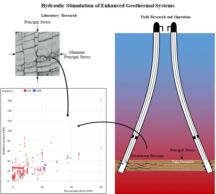
- The increase in minimum horizontal stress increases the formation breakdown pressure.
- The review of Iaboratory tests concluded that for various rock types, having a different internal structure, like bedding planes or natural fractures, using high viscous fluid resulted in an over proportional high formation breakdown pressure.
1. Introduction
Ever since the discovery of shale oil and gas, there had been considerable growth in the implementation of stimulation techniques, in particular, hydraulic fracturing. What was once a mere effort to recover the lost reservoir permeability due to fines migration, had become the key element in accessing and producing vast hydrocarbon resources that eventually altered the balance of supply and demand in the global market, probably for years to come. To keep up with this new trend, the focus of several research projects was shifted as well, investigating every possible detail of the fracturing process, under the effect of numerous variables both in the reservoir and in control of the operator. Among all this work, special attention was also given to reservoirs withholding great amounts of geothermal energy, securing the research projects not only a spot for contribution in the oil and gas recovery but also in the popular topic of renewables.
Geothermal energy has been gaining more and more popularity around the world, partly for its green nature and low emissions and partly due to its year-round availability. Acquired in the form of hot water, geothermal energy is not only utilized by households and communities for heating or cooling purposes but can also be tapped into for high-enthalpy applications such as electricity generation. While the former is essentially feasible almost everywhere, the latter applies to locations with a significantly high geothermal gradient to deem the process practically and economically successful.
The high-temperature zones exist mainly in very deep layers of the earth’s crust, typically in crystalline rocks and close to the earth’s mantle. Accessing these layers requires one or more wellbores drilled through hard rocks as well as a permeable reservoir into which water can be injected, allowed to flow through, heat up, and then produced again back to the surface. Such conditions are not always met, and often major modifications are essential to prepare the system and make it functional. Therefore, such manipulated producing systems are commonly referred to as Enhanced/Engineered Geothermal Systems (EGS).
Although technologies involved in exploration, drilling, and production of EGS are for the most part adapted from the petroleum industry, some challenges are uniquely encountered in EGS, predominantly as a result of reservoir rock type and the production rates. One of such challenges is the stimulation of reservoir rock to create fractures and compensate for the low permeability expected in crystalline formations. Thermal, chemical, and hydraulic fracturing, together with hydro-shearing, have all proven to be effective methods in either recovering the permeability or improving it beyond its existing status. Among these methods, hydro-shearing and especially hydraulic fracturing have shown the best efficiency. In hydro-shearing, fluid is injected at lower pressures only to slide the already existing fractures open, whereas, in hydraulic fracturing, high-pressure fluid is injected to create and extend new fractures. To keep the fractures open, proppants can be mixed with the stimulation fluid.
The success of a stimulation job depends on a variety of factors. The natural fracture state of the reservoir, in-situ stress conditions, and physical properties of the rock itself play the biggest role in the number and length of the generated fractures. Additionally, these parameters define the boundary conditions of a stimulation job and assist in control and monitoring as a crucial requirement, specifically because a poorly designed process can lead to catastrophic seismic events. However, reservoir parameter characterization is a complex task as the parameters involved often vary substantially from one reservoir to the other, creating new and alternating operating restrictions.
After accomplished fracturing process, the well is put into production by usually installing an artificial lift system. For low rate production sucker rod pumps and hydraulic pumps [1] are used, whereas high rate production requires electric submersible pumps. Fractured formations tend to produce fines along with the reservoir fluid due to the damages initiated during hydraulic fracturing. Serious research was performed in the past to mitigate problems of artificial lift systems, associated with fines production [2], [3], [4] [5], and new technologies [6], [7] and laboratory testing capacities [8], [9] have been introduced. Over the past decade, much time and effort have been dedicated to better understand the key factors that drive an EGS fracturing project towards success. A further aim has also been to improve the public acceptance of geothermal projects in general, and the projects implementing hydraulic fracturing techniques in particular. Numerous studies were undertaken all across the world, particularly in locations with potentials for high-enthalpy geothermal energy recovery. Such efforts could be characterized into the following categories: Computer modeling and simulation, Laboratory experiments, Field experiments, Demonstration projects;
This paper will review the results of these studies, as well as the operational projects, classify them, and provide comparisons based on their key common attributes. The goal is to presents a thorough overview of the state of the art, as well as the global know-how and expertise, which can be useful for current and planned projects.
2. Laboratory scaling laws and fracture propagation detection
So far several artificial and rock sample types have been used to evaluate the performance of hydraulic fracturing in the lab scale. To transfer the small-scale lab test results into large-scale field hydraulic stimulation operations, special scaling laws need to be considered [10]. These laws scale the laboratory experiments in terms of energy rates associated with stimulation fluid flow, fracture opening width, and rock segmentation. Besides, the lab test requirements, conditions such as proper time for data acquisition, field-like fracture propagation, and the containment of the hydraulic fractures within block boundaries need to be fulfilled.
The boundary definition of a laboratory conducted hydraulic fracturing experiment requires the proper selection of the fluid injection rate, the fluid viscosity, and the total fracture propagation time [11]. These parameters can be obtained from the mentioned scaling laws, if the sample size, the wellbore size, and the mechanical properties of the sample are given. The fracture propagation time is measured from the fracture initiation time point, which is given by the maximum pressure. Fracture initiation occurs before the breakdown point [12]. The following dimensionless parameters have been introduced by De Pater et al. [10] to scale down from the field scale to lab scale. is the dimensionless time of the experiment, represents the crack formation, is the elastic deformation, is the fluid leak-off, and represents the confining pressure.
where is the wellbore radius, is the time of the experiment, represents the separation energy, E is the sample’s Young's modulus, is the Poisson's ratio, is the confining stress, and is the leak-off coefficient. Because of the low injection rate in laboratory experiments, to fulfill the scaling laws, highly viscous fluids are required to be used. The scaling laws discuss various fracture propagation regimes. In the field, fracture propagation is influenced by three extreme boundaries: viscosity domination, toughness domination, and leak-off-domination [13]. During the fracture initiation phase, the fracture regime is toughness-dominated, but it later becomes viscous-dominated [14]. A radial fracture develops a toughness-dominated regime at the final stage of fracture extension [15]. According to Detournay et al, the dimensionless toughness parameter “” of a penny-shaped fracture can be calculated according to (6. Viscous dominated regimes are achieved by keeping equal or smaller than 1. In contrast, equal or bigger than 4 results in a toughness-dominated regime:
where is the experiment duration, is the fracturing fluid viscosity, is the plain strain module, and is a toughness-dependent parameter. The material parameter definition was provided by Bunger et al. [12], where is the fracture toughness:
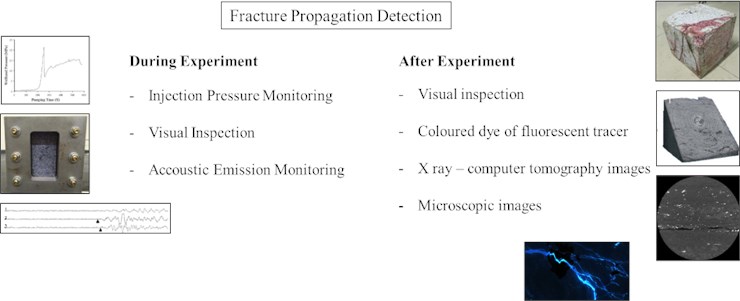
The detection and the evaluation of the fracture propagation in the stimulated samples can be done by using different technologies (Fig. 1). Typically during the experiments, injection pressure monitoring and acoustic emission monitoring are performed on the rock samples. The acoustic emission monitoring allows the interpretation of the fracture type. A sudden burst of acoustic emission activity is driven by tensile fracturing, whereas the exponential increase of the acoustic emission rate is typical of shear fractures. A special test cell can in this case be used, which allows the visual inspection of the fracture growth through a thick plexiglass window by a high-speed camera. After the experiment, a visual inspection of the flow paths with colored dye- or fluorescent tracer-contained stimulation fluid is performed. Besides, 3D scan images, X-ray computer tomography images, and/or microscopic analysis are performed.
Fig. 1Fracture propagation detection
3. Laboratory hydraulic fracturing tests
Laboratory hydraulic fracturing experiments conducted since 1970 tries to investigate fracture propagation under different stress conditions, injection pressure, and rock types. Early tests showed that the injection pressure has a considerable effect on the hydraulic fracture initiation, whereas the injection rate influences the fracture propagation [16] (Zoback et al., 1977) significantly. Qian et al. [17] have presented a compilation of advances in laboratory-scale hydraulic fracturing experiments and facilities. This review concentrates on an analysis of the tests performed by scientists all over the world and presents interrelationships between the methodologies and results. The review starts with an overview of investigations done on consolidated sand as well as artificial rock samples, like cement, concrete, and hydrostone during fracturing tests. In such hydraulic fracturing experiments, the emphasis was laid on the evaluation of the hydraulic fracturing process in typical oil and gas reservoir rocks. Sandstone, carbonate, and shale rock fracturing experiments were therefore also performed. However, climate and political changes pushed the development of renewable energy sources and enhanced geothermal systems und currently under research.
As a result, numerous papers were published in the recent ten years, presenting laboratory hydraulic fracturing results of igneous rocks. Hence, the focus of this work will be laid mainly on such experiments. In total, more than 600 laboratory hydraulic fracturing experiments were investigated in the current review.
Fig. 2 presents a summary of the applied fracture propagation detection techniques. All of the experiments applied visual fracture detection right after the experiment. Experiments with granite and sandstone were typically monitored by the recording of the acoustic emissions and CT scans, done after the hydraulic fracture stimulation.
Fig. 2Fracture propagation detection statistics
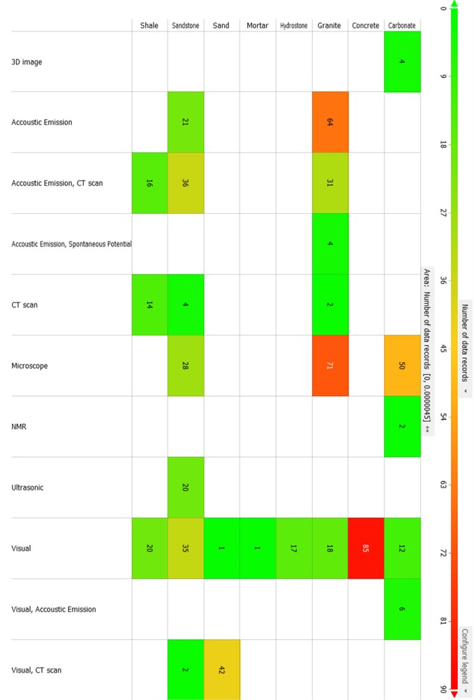
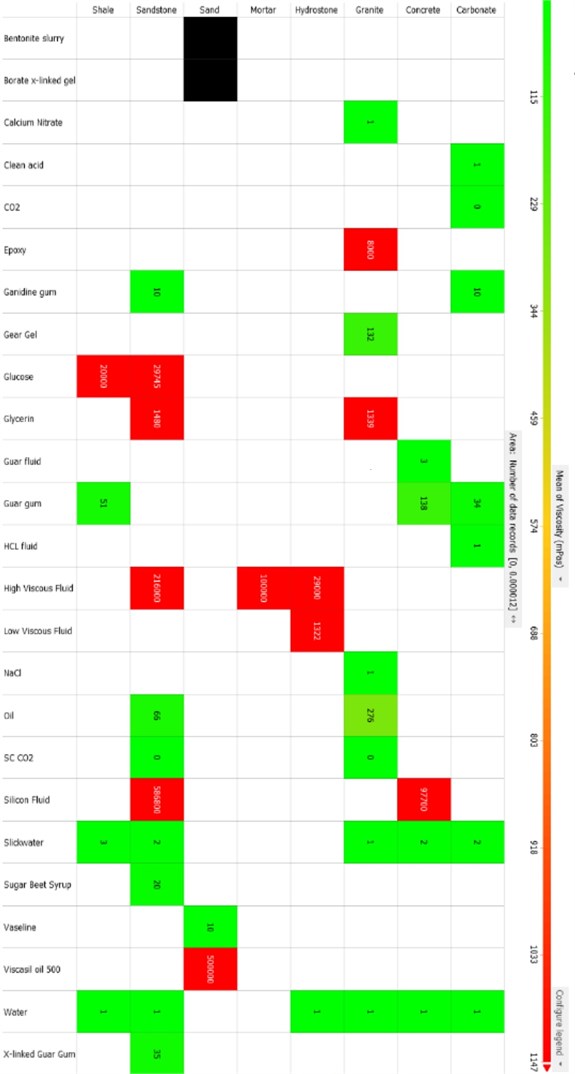
Fig. 3 shows the selected stimulation fluid types for the different samples and their mean viscosity. Some of the laboratory experiments were performed, using scaling laws, others not. Those which applied to scale laws used high viscous fluids like glucose, silicon-based fluid, epoxy, or viscasil oil. Nevertheless, the majority of experiments were performed with low viscous fluid, like water, slickwater, supercritical CO2, or even CO2 in the gaseous state. The color black indicates no available information.
Fig. 3Stimulation fluid types and viscosities
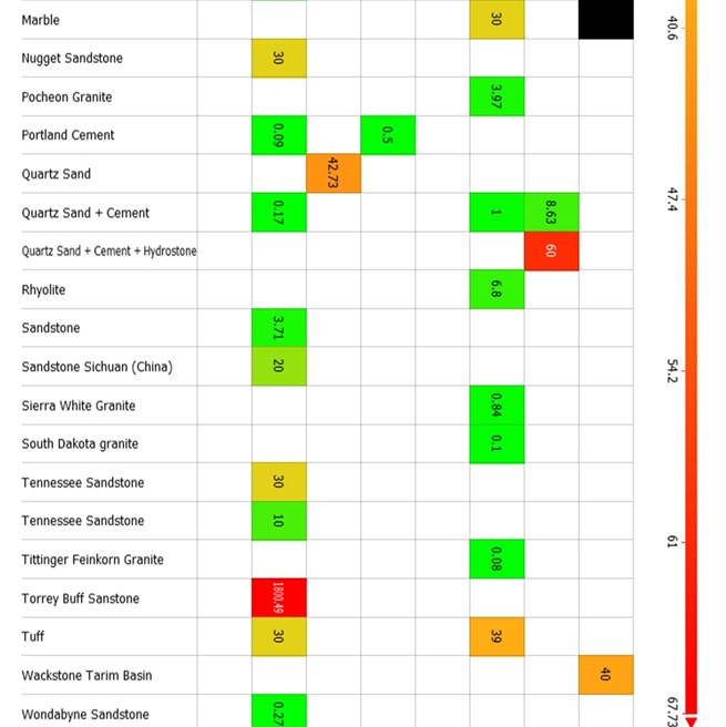
During the experiments, different fluid injection rates have been used. The injection rates range from less than 0.01 ml/min up to almost 2,000 ml/min. Fig. 4 and Fig. 5 give an overview of the typical rates used for the specific rock types. For sandstone samples, the biggest range of injection rates was tested, whereas for granite and carbonate samples an injection rate between 1 ml/min and 30 ml/min was chosen. Fig. 5 summarizes the different rock types and it can be seen that samples were selected from outcrops in countries related to tight sand and shale hydrocarbon reservoirs. Besides, igneous rock samples for the investigation of the fracturing process for enhanced geothermal systems have been selected, mostly in Europe and North America.
Fig. 4Sample types, specifications, and average stimulation fluid injection rate
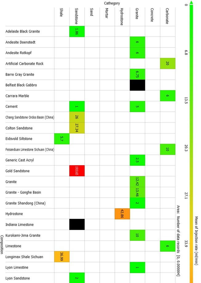
Fig. 5Sample types, specifications, and average stimulation fluid injection rate (cont.)
3.1. Conducted lab experiments based on rock type
Due to the wide application of fracturing techniques, especially in oil and gas production, many studies were performed on different types of reservoir rocks encountered to create a reliable knowledge foundation for this practice around the globe. Experiments have been performed on a variety of different rocks as named before, each analyzing not only the change of variables specific to the rock type but also general properties that are equally important in all.
For instance, for consolidated sands, parameters such as grain size distribution as well as fracture propagation across cylindrical, homogenous samples were mostly investigated under ambient and biaxial stress state. For cement, the only available study, published by Beugelsdijk et al. [18], focused on the influence of the flow rate and fracturing fluid viscosity on hydraulic fracture propagation. For concrete, an artificially constructed material, triaxial stress resistance, and the homogeneity of the samples despite different compositions were a key interest. A similar approach applies to hydrostone as the strongest and hardest gypsum cement available. For carbonates, which compose mainly of CaCO3, fracture propagation along with stylolite structures and calcite veins are predominantly of interest and for shale, fine-grained clastic sediment, the propagation of fracture under different stress regimes is of critical importance.
Additionally, a great amount of effort has been given to sandstone as they build the basis for some of the biggest gas and oil reservoirs in the world [19]. Besides, a significant number of geothermal power plants use sandstone reservoir layers for fluid production and injection. Despite their generally acceptable permeability, in tight formations or formations with interlayer bedding, hydraulic fracturing is applied to improve the productivity of the formation. On the one hand laboratory tests have been performed for the performance analysis of the acoustic emission fracture propagation technique and homogenous sandstone samples have been fractured to investigate the fracture initiation [12], growth, and performance regarding special procedures, like cyclic fluid injection or the injection of supercritical carbon dioxide. On the other hand, the fracture propagation across natural and artificial discontinuities or even alternating layers of low permeable layers has been tested.
Aside from the individually observed parameters mentioned above, observation of the state or changes of other properties such as the type of fracturing fluid as well and formation breakdown pressure concerning minimum horizontal stress, vertical stress, or their ratio is a desirable outcome for each rock type experiment. Tables 1 to 6 provide a summary of experiments conducted on each rock type.
Table 1Sand laboratory experiments
Name | Reference | Bentonite slurry | Borate x-linked gel | Vaseline | Viscasil oil 500 |
De Pater et al., 2007 | [20] | 5 | 13 | 6 | |
Bohloli et al., 2006 | [21] | 4 | 9 | 5 | |
Olsen, 2011 | [22] | 1 |
Table 2Concrete laboratory experiments
Name | Reference | Guar fluid | Guar gum | Silicon fluid | Slickwater | Water |
Dehghan et al., 2015 | [23] | 18 | ||||
Fallahzadek et al., 2015 | [11] | 8 | ||||
Chen et al., 2010 | [24] | 18 | ||||
Zhang et al., 2018 | [25] | 11 | ||||
Tie-gang and Zhang, 2014 | [26] | 6 | ||||
Zhou et al., 2008 | [27] | 10 | ||||
Zhou et al., 2017 | [28] | 14 |
Table 3Hydrostone laboratory experiments
Name | Reference | High viscous fluid | Low viscous fluid | Water |
Gosavi et al., 2017 | [29] | 1 | 2 | |
Kim and Abass, 1991 | [30] | 14 |
Table 4Sandstone laboratory experiments
Name | Reference | Guanidine gum | Glucose | Glycerin | High viscous fluid | Oil | SC CO2 |
De Pater et al., 1994 | [31] | 13 | |||||
Behrmann and Elbel, 1991 | [32] | 3 | |||||
Athavale and Miskiminis, 2008 | [33] | 2 | |||||
Bunger et al., 2015 | [34] | 11 | 9 | ||||
Anderson, 1981 | [35] | 2 | |||||
Warpinski et al., 1982 | [36] | 2 | |||||
Zou et al., 2018 | [37] | 6 | |||||
Patel and Sondergeld, 2017 | [38] | 6 | |||||
Lou et al., 2017 | [39] | 2 | |||||
Silicon Fluid | Slickwater | Sugar Beet Syrup | X-linked Guar Gum | Water | |||
Behrmann and Elbel, 1991 | [32] | 6 | |||||
Stoeckhert et al., 2015 | [40] | 7 | |||||
Daneshy, 1978 | [41] | 7 | |||||
Stoeckhert et al., 2020 | [42] | 36 | |||||
Casas and Miskiminis, 2006 | [43] | 2 | |||||
Warpinski et al., 1982 | [36] | 9 | |||||
Zou et al., 2018 | [37] | 2 | 2 | ||||
Jianming et al., 2017 | [44] | 5 | |||||
Brenne et al., 2013 | [45] | 28 |
Table 5Carbonate laboratory experiments
Name | Reference | Clean acid | CO2 | Guanidine gum | Guar gum | HCL | Slick-water | Water |
Brenne et al., 2013 | [45] | 50 | ||||||
Stanislawek et al., 2017 | [46] | 4 | 4 | 4 | ||||
Hou et al., 2019 | [47] | 2 | 1 | 1 | ||||
Baohua et al., 2019 | [48] | 6 | ||||||
Wei et al., 2017 | [49] | 2 |
Table 6Shale laboratory experiments
Name | Reference | Glucose | Guar gum | Slickwater | Water |
Cheng et al., 2015 | [50] | 1 | |||
Guo et al., 2014 | [51] | 14 | |||
Heng et al., 2019 | [52] | 6 | |||
Hou et al., 2018 | [53] | 1 | 4 | ||
Jianming et al., 2017 | [44] | 5 | |||
Kear et al., 2017 | [54] | 4 | |||
Ma et al., 2017 | [55] | 6 | |||
Zhang et al., 2019 | [56] | 9 |
In Fig. 6, Fig. 7, Fig. 8, and Fig. 9, the formation breakdown pressure vs. minimum horizontal stress for different fluids and rock types are depicted.
In Fig. 10 and Fig. 11, the effect of stress ratio is drawn for concrete and hydrostone.
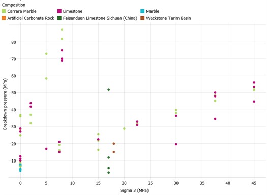
Fig. 12 and Fig. 13 compare the breakdown pressure vs. minimum horizontal stress concerning rock composition.
Fig. 6Breakdown pressure – minimum horizontal stress relationship – fluid types – sand
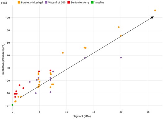
Fig. 7Breakdown pressure – minimum horizontal stress relationship – fluid types – concrete
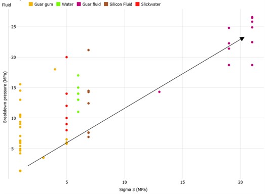
Fig. 8Breakdown pressure – minimum horizontal stress relationship – fluid types – sandstone
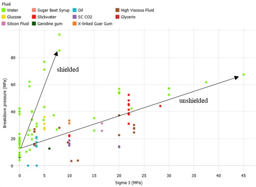
Fig. 9Breakdown pressure – minimum horizontal stress relationship – fluid types – carbonates
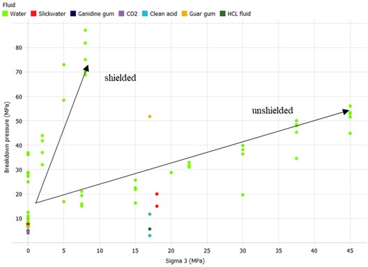
Fig. 10Breakdown pressure – stress ratio – concrete
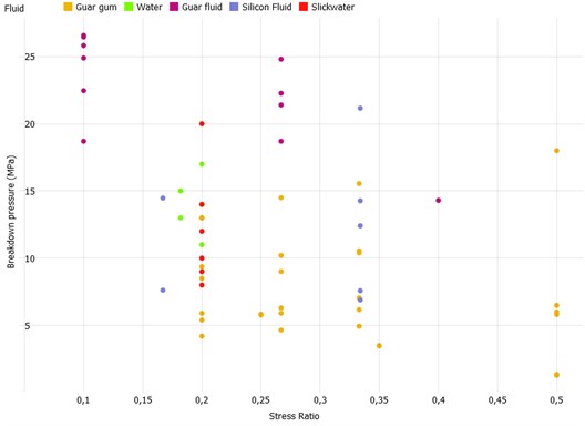
Fig. 11Breakdown pressure –stress ratio – hydrostone
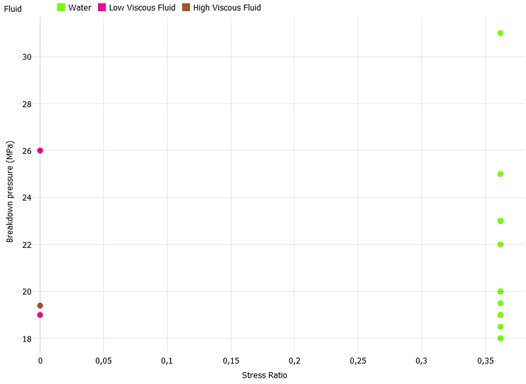
Fig. 12Breakdown pressure – minimum horizontal stress relationship – sandstone composition
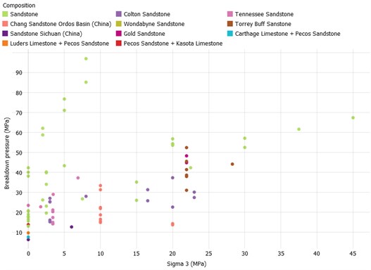
Fig. 13Breakdown pressure – minimum horizontal stress relationship – carbonates composition
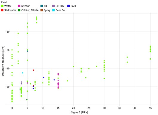
3.2. Igneous rocks
Due to the significance of igneous rocks in enhanced geothermal systems, more thorough research was conducted on the previous attempts at characterizing fractures in such rocks. Granite, as the most commonly encountered rock in EGS, is an igneous rock, composing of feldspar, quartz, and glimmer, and can be produced at every stage of a Wilson cycle [57]. As geologically young igneous formations are associated with magmatic processes, depending on the formation age, their temperature is typically higher than those of other formations in equal depth. As a result, igneous rock formations are ideal candidates for geothermal energy recovery. The recovery of geothermal energy from these formations requires hydraulic stimulation, as the natural permeability of the igneous rock is too low, to allow effective fluid flow. Laboratory tests have been performed in the past with several objectives to understand the hydraulic fracturing behavior in igneous rock samples. The target was to develop an effective thermal and hydraulic fracturing scheme. Table 7 provides a detailed summary of the fluid types tested.
Table 7Igneous rocks laboratory experiments
Name | Ref. | Calcium nitrate | Epoxy | Gear gel | Glycerin | NaCl | Oil | SC CO2 | Slickwater | Water |
Brenne et al., 2013 | [45] | 65 | ||||||||
Chen et al., 2015 | [24] | 2 | 2 | 2 | ||||||
Cheng et al., 2020 | [58] | 13 | ||||||||
Craig, 2016 | [59] | 11 | ||||||||
Dep et al., 2019 | [60] | 1 | ||||||||
Diaz et al., 2018 | [61] | 25 | ||||||||
Frash, 2012 | [62] | 1 | 2 | 2 | ||||||
Hampton et al., 2008 | [63] | 1 | ||||||||
Hu et al., 2016 | [64] | 2 | 2 | |||||||
Hu et al., 2019 | [65] | 2 | ||||||||
Ishida et al., 2012 | [66] | 2 | 2 | |||||||
Jia et al., 2013 | [67] | 2 | ||||||||
Jianming et al., 2016 | [68] | 1 | ||||||||
Siebert et al., 2015 | [69] | 2 | ||||||||
Siebert, 2017 | [70] | 20 | ||||||||
Xing et al., 2019 | [71] | 4 | ||||||||
Zhou et al., 2018 | [72] | 3 | ||||||||
Zhuang et al., 2020 | [73] | 20 |
Tests on igneous rocks were performed under ambient, uniaxial, biaxial, and triaxial conditions. A test setup for the evaluation of the effect of hydraulic pressure on flaws, or existing fractures, under uniaxial load, has been developed at the MIT [74]. The test setup uses a transparent window to record the fracture propagation by a high-speed camera where granite and marble rock fracturing tests have been performed. First fracturing laboratory tests in 1980 indicated that rapid fluid injection rates result in tensile fractures, whereas slow injection rates cause shear failures at elevated differential stress levels [75]. There a triaxial hydraulic fracturing test system was used in the laboratory to investigate the planar and three-dimensional geometry of hydraulic fractures in homogenous volcanic rocks (rhyolite, tuff). CT scan technology was used to scan the rock samples before and after the fracturing experiment to evaluate the hydraulic fractures in three dimensions [67]. The images indicate that the hydraulic fractures cross natural pores and microcracks. No fracture propagation has been seen in zones where the natural pores are abundant since the high fracture pressure gradient of volcanic rocks generally required high fracturing pressures. The rock mechanical properties near the borehole were seen as the key factors controlling the initiation and propagation of hydraulic fractures. Additionally, a study of the reservoir stimulation process on a laboratory scale was performed by Hu et al. [64] to improve the understanding of the fracture geometry for the fracturing of magmatic rocks under triaxial conditions.
Moreover, acoustic emission monitoring was used to investigate the fracture propagation in several Sierra White granite rock samples with one injection well and four producing wells [65]. The low viscosity of the selected fracturing fluid allowed a rapid fracture development. In just 1.4 seconds, the fracture propagated near the rock’s surface. A good agreement between the reconstructed 3D fracture geometry and the acoustic emission monitoring results was found. The SEM analysis showed that the average fracture aperture is 139 μm and that the fracture follows the weak boundaries between the Quartz and Albite grains or the weak beddings in the grains.
Furthermore, Ishida, T., et al, have performed triaxial fracturing experiments with water, oil, and supercritical CO2 [66], [76], [77]. The laboratory tests were performed on six granite samples to investigate how the viscosity of fracturing fluid affects fracture propagation. The wellbore was situated parallel to the rift plane of the granite samples. The results indicated that higher viscous fluids yield a smoother fracture pattern. In general, hydraulic fracturing induces several branch pathways around the main fracture. Supercritical CO2 caused the most branches along the main fracture and confirms that low viscous fluids will form a more complex fracture network in rocks. The acoustic emission monitoring system showed that shear fracturing is predominant for the low-viscosity supercritical CO2 injection, which is conformed by the microscopic analysis.
Chen et al. [24] investigated the influence of the fracturing fluid type (water, oil, and supercritical CO2) on the fracture propagation in anisotropic granite under true triaxial load too. The evaluation used a microscopical analysis via the fluorescent method. The observed results confirm the findings of Ishida et al. [77]. Fig. 14 shows that most of the laboratory tests were performed with pure water. Supercritical CO2 resulted in low breakdown pressures, depending on the structures of the rock sample.
Fig. 14Breakdown pressure – minimum horizontal stress relationship – fluid types – igneous rocks
Dense microcracking near coalesced fractures is an important process in altering the mechanical properties of the nearby virgin material. A detailed acoustic emission monitoring and analysis study has been performed to get insight into the formation of microcracks and their characteristics [63]. The post-processed results showed that there is a relationship between the microcrack displacement vector orientation and principal stress directions. It was concluded that tensile event displacements tended to form at different angles than shear-dominated failures.
Elsewhere, the development of microcracks in hot concrete and granite samples without confining pressure by the injection of room temperature water was investigated to develop an understanding of the thermal fracturing behavior [78]. Visual inspection, bubble leakages, pressure decay, acoustic signatures before and after the experiments, and CT scans were used to characterize the microcrack propagation. The borehole pressure decay profiles, obtained before and after each stage of stimulation indicate an increase in sample permeability.
In another effort, an experimental examination of thermal and hydraulic fracture propagation in acryl, cement, and granite samples was performed to validate theoretical results and study the fracture morphologies under uniaxial stress conditions [59]. Different sequences of thermal and hydraulic fracturing were selected. In general, the fractures were created with the faces perpendicular to the maximum principal stress. The sample breakdown pressure was almost half in acrylic specimens when thermal fracturing was applied before. Besides, the Kaiser effect [79] can be used during the thermal stimulation as an indicator of pre-existing fractures or previous stress states. The CT scans showed that thermal fractures create significant permeability, but the fractures remain almost completely closed when the temperature gradients disappear.
True triaxial hydraulic fracturing tests were as part of another study to evaluate the effect of the injection rate, the rock temperature, and the applied stress on the formation breakdown pressure of selected granite samples [58]. Visual and microscopic evaluation methods have been used. In the first test series, the injection rate was increased from initially 5 ml/min to 30 ml/min in 5 ml/min steps at a sample temperature of 150 °C. The results indicated a clear increase in breakdown pressure with the rate increase. The second test series investigated the effect of temperature. The temperature of the rock sample was increased from 30 °C to 120 °C in 30 °C steps. As high temperatures cause thermal stresses inside the rock matrix during the injection of cold fluid, the small thermal-induced cracks weaken the boundaries between grains and the breakdown pressure linearly descends with rock temperature at constant stresses. Finally, the effect of confining pressure on breakdown pressure showed that an increase in confining pressure results in an increase in breakdown pressure. The discrete elements numerical simulation showed an acceptable agreement with the experimental results.
In a different investigation, a comparison of formation breakdown pressure in granite samples at 20 °C and 120 °C was performed for a low and a high-stress state [71]. It was concluded that different temperatures do not cause a significant change in the fracture geometries, but at 120 °C, the injection pressures trend shows two peaks, and fracture pressures are increased by 3.6 to 4.9 MPa, which is controversial to the findings of Cheng et al. [80]. At high-temperature, reduced fracture energy as well as a reduction in fracture width was recorded, which indicates that high temperatures decrease the effective stimulated volume of hydraulic fracturing.
In addition, a hydraulic fracturing process in an enhanced geothermal system was simulated by true triaxial laboratory tests, applying temperatures of up to 250 °C [72]. Granite and marble samples with and without natural fractures were taken from an outcrop in a Chinese EGS project. The tests showed that the matrix of the selected hot dry rock sample without natural fractures was difficult to fracture. Natural fractures have a significant influence on fracture initiation and propagation. An extreme decrease in fracture pressure has been seen for the comparison of rock samples with and without natural fractures. A higher fracturing fluid pump rate resulted in the connection of more natural fractures. A finite element method-based numerical simulation model coupled with thermal conductivity, fluid flow, and rock mechanics was used to simulate the fracturing process.
Another modeling example is the discrete element model of naturally fractured rock presented by Zang et al. [81] as a means to simulate the seismic events of a soft stimulation method with cyclic reservoir treatment. The simulation results show a good fit for energy released by seismic events. Cyclic injection reduces the number of induced events as well as the magnitudes. Triaxial laboratory experiments confirmed the finding of the cyclic simulation treatment of smaller damage volume and more persistent fracture growth [82], [83].
Laboratory experiments on the damage evolution during cyclic injection using acoustic emission monitoring were also carried out on cylindrical granite samples [61]. The average breakdown pressure, obtained from the continuous injection experiments was taken as a reference. The cyclic injection experiments resulted in the conclusion that the level of maximum injection pressure is inverse to the number of cycles to failure and the maximum amplitude of the acoustic emission reduction during the cyclic injection. On the one hand, hydraulic energy was higher for cyclic injection, but on the other hand, the radiated seismic energy was lower.
Furthermore, the effect of six different injection schemes on the fracturing behavior of granite under triaxial load was investigated by Zhuang et al. [73]. Three schemes were injection rate controlled: constant rate continuous injection, stepwise rate continuous injection, and cyclic progressive injection, whereas the other three schemes were pressurization rate controlled: stepwise pressurization, stepwise pulse pressurization, and cyclic pulse pressurization. The fracture propagation was monitored by an acoustic emission system. The results indicated that the intragranular fractures splitting microcline, orthoclase, and quartz grains dominated the hydraulic fractures independent of the injection scheme, which results in tensile fractures. Stepwise pulse pressurization created the largest fracture length and the highest injectivity enhancement. Cyclic pulse pressurization has been known to be the best method regarding hydraulic performance improvement and induced seismicity reduction. Cyclic progressive injection generated the lowest average magnitude of the maximum acoustic emission amplitude.
Other efforts led to an investigation of hydraulic fracturing of igneous rocks under triaxial stress on a laboratory scale was performed by Siebert et al [69], [70]. Granite rock samples were tested and an acoustic emission monitoring system was used for fracture propagation monitoring. An injection procedure was developed, which reduces the negative influence of decompression on the fracture propagation by at least two injection cycles. The first cycle is applied for pre-damaging the samples by rising the injection pressure until fracture initiation. For the second cycle, the injection rate was reduced and the fracture propagated effectively into the rock.
A different work was described as testing of the mechanical impulse hydraulic fracturing method on samples of acrylic, concrete, granite, and limestone was performed under triaxial load and elevated temperature level [62], where fracturing fluids water, brine, oil, and epoxies were selected.
A benchmark test for verifying existing or new hydraulic stimulation codes was also performed based on a laboratory fracturing test, using igneous and metamorphic rock samples [60], [84]. Fracture growth and propagation were monitored by acoustic emissions and visually by ink injection. A better match between experiment and simulation results is obtained for larger values of fracture toughness, which is a result of the fact that with increasing fracture size, the fracturing behavior shifts from ductile towards brittle behavior. The final fracture extent of simulation and results are equal. The chemical response of fractured crystalline rocks to variations in temperature and stress is significant for fluid transport through fracture pathways.
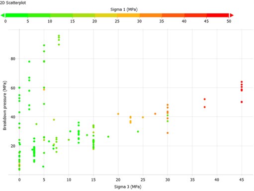
In the meantime, laboratory research is going on at the U.S. DOE’s Frontier Observatory for Research in Geothermal Energy (FORGE) to validate the reactive transport and/or mechanical models for better prediction of fracture conductivity [85]. The most important parameters are identified to be the injection rate, fluid infiltration, fluid viscosity, borehole size, and injection scheme [86]. Typically, acoustic emissions monitoring is performed to detect fracture propagation in the rock samples. After fracturing, the rock samples are often analyzed by using CT scans or microscopes. Fig. 15 shows that the influence of the internal structure of the rock sample influences the breakdown pressure at low minimum horizontal stresses. Nevertheless, for large minimum horizontal and vertical stresses, the breakdown pressure is mostly dependent on their magnitudes.
Fig. 15Breakdown pressure – minimum horizontal stress relationship – vertical stress – igneous rocks
3.3. Tests combining samples of different rock types
Brenne et al. [45] performed hydraulic fracturing tests on six triaxially loaded rock samples of different compositions. Distilled water was pumped into the borehole, positioned in the center of the cylindrical sample, or into a polymer tube inside the borehole. The objective was to investigate the different fracture propagation of hydraulic and sleeve fracturing. Stable fracture propagation was achieved over a wide range of injection pressure for sleeve fracturing. The experiments showed that fracture initiation can be confidently linked to the acoustic emission count rates. A comparison to fracture modeling showed that simple fracture mechanics models can predict the experimental outcome.
A series of laboratory fracturing tests were also performed on granite, sandstone, and shale with different bedding plane directions (0, 30, 45, 60, 90), where the interlayer bonding force is relatively low [68]. Cylindrical samples were prepared and an X-ray computer tomography scanner was employed to obtain the spatial distribution of hydraulic fractures. One of the most significant parameters on the propagation of hydraulic fractures is the initial heterogeneities in rock materials. In shale, the fracture direction is diverted into the bedding plane direction while fracture extension in sandstone, shale, and granite cores differ extremely. The fractures in fractured granite cores are more tortuous than those in fractured sandstone and shale cores, which might be the result of the initial heterogeneity of granite.
Elsewhere, testing of unconventional rocks (concrete, granite, limestone), having low natural permeability and heterogeneous structures, was performed to test the mechanical impulse hydraulic fracturing method, measurement of critical state hydraulic fracture aperture, and investigate the grain-scale effects on 3D hydraulic fracture geometry [62]. Tap water, oil, and different types of epoxy were used as fracturing fluid. The laboratory results allowed insight into the hydraulic fracturing process benefiting from the direct comparison of pressure, flow rate, acoustic emissions (AE), strain, temperature, self-potential (SP), and fracture geometry data.
4. Field research
Laboratory tests allow the evaluation of the breakdown pressure and the fracture propagation under various load conditions, stimulation fluid types, and injection rates. Nevertheless, these tests cannot clarify all uncertainties for hydraulic stimulation of rocks, like fracture propagation direction and extent as well as large-scale bedding plane and fault influences. To overcome the laboratory limitations, in the last couple of years, four field-scale laboratory setups/ research programs, three in the United States and one in Switzerland, were started.
4.1. kISMET – USA
An interesting field test facility is the “kISMET” (permeability (k) and Induced Seismicity Management for Energy Technologies) project as a collaboration of multiple laboratories and universities, constructed in 2015 in a deep mine. The purpose of the project was to conduct hydraulic fracturing experiments in crystalline rock to understand the effects of stress field and rock fabric on fracturing efficiency and permeability enhancement, as well as to gain experience in geophysical monitoring methods. Such an environment provides the best possible stress field characterization of the stimulation operations downhole and offers close-by monitoring opportunities. The test site was about 1,500 m underground at the Sanford Underground Research Facility (SURF) in Lead, South Dakota. Five wellbores were drilled almost vertically and cored, every 3 m spaced from the next, with one injection borehole approximately in the center and a depth of 100 m, surrounded by the other 4 wellbores used for monitoring and drilled to a depth of 50 m. The project offered a great opportunity to gain experimental experience. Additionally, it was observed that hydraulic fractures were formed quite uniformly, meaning that the rock fabric did not have a significant effect on controlling the fracture orientation. Seismic monitoring also only recorded a marginally higher signal when the deepest fractures were created [87].
4.2. Collab – USA
The US Department of Energy-funded research to be carried over several years by several partners and laboratories, referred to as the EGS Collab project. The main aim of the project is to improve and validate the thermal, chemical, mechanical, and hydrological models with the data obtained from the field. The tests are carried out at the 1500 m deep SURF in South Dakota, at intermediate scale test beds (~10 m). The test bed is consisted of eight wellbores, having a depth of 60 m, six used for instrumentation and monitoring, and the other two are used for injection and production. The results are used to support the FORGE project. At the site, three experiments were planned to be conducted:
- Experiment 1: To perform and characterize several heavily monitored stimulations. Measuring stimulation behavior, permeability enhancement, and rock characteristics would provide insight into the nature of the stimulation (fracturing, shearing, mixed-mode or thermal) under similar-to-reservoir conditions [88].
- Experiment 2: The experiment is similar to Experiment 1, but with the difference that it focuses on hydraulic shearing of an existing fracture, as opposed to hydraulic fracturing [89].
- Experiment 3: The experiment will investigate other alternative stimulation techniques or general operational methods to better extract heat from the EGS reservoir [90].
4.3. FORGE Utah – USA
Frontier Observatory for Research in Geothermal Energy (FORGE) is driven by the U.S. Department of Energy’s program. The program came to existence to develop and practice techniques that allow for accessing, exploiting, and monitoring EGS reservoirs in different locations around the United States, to demonstrate the potentials of the EGS technologies and their role in the power generation to the energy industry, investors and the public. The FORGE program was performed in three phases. Phase 1 was the preliminary study of existing data from five different sites around the US. Eventually, in 2018, the University of Utah’s Milford, Utah site was selected to be the first site for the FORGE laboratory. As part of Phase 2, well 58-32 was drilled with a total depth of 2,290 m into permeable, crystalline rocks to provide a direct measurement of reservoir parameters such as temperature, rock type, permeability, and stress in the reservoir, as well as to define the groundwater depth. In phase 3, two additional wells were drilled and completed to be used for seismic monitoring and to complete the infrastructure for research and development, testing, and observation [91]-[93].
4.4. GTS – Switzerland
In Switzerland, as part of the government energy strategy 2050, the Swiss Competence Centres for Energy Research (SCCER) has initiated a research network to conduct innovative and sustainable research on renewable and emission-free forms of energy. To investigate the geothermal potential, two test sites were selected in the Swiss Alps where in-situ tests could be performed under conditions that are as close as possible to an EGS.
The first site, called Grimsel Test Site (GTS) was used for experiments from 2015 and 2017, on the scale of decametre. The second site called the Bedretto Underground Laboratory for Geoenergies (BULG) will be compatible with tests performed on the hundred-meter scale and will be explained later in the paper. The significance of these test sites is in the fact that they are comparable in terms of scale to the Basel EGS project. These in-situ tests will be supported by laboratory tests as well. The GTS was initially developed in the 1980s for the disposal of nuclear waste and is located 450 m below the surface within Crystalline rocks, in particular granodiorites. Both, hydro-shearing and hydro fracturing, was tested at the site in six experiments conducted on two wellbores with 45 m depth and water are stimulation fluid [94].
5. Field operation
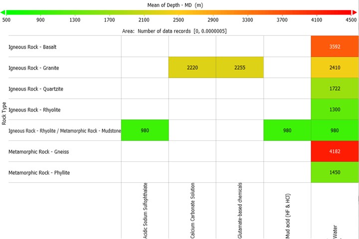
Numerous EGS projects have been installed in the last decade in the US, Europe, and Asia. Most of these projects are scientifically accompanied and information is published. Besides those published in Breede et al. [96], several additional EGS projects are operated and planned. Most of the EGS wells target igneous rock, like basalt, granite, etc., and have an average depth of about 2,500 m. Nevertheless, depending on the local geothermal gradient, depths as shallow as 1,000 m and as deep as 4,200 m are targeted by the wells (Fig. 16).
Fig. 16Most wells target low permeable igneous or metamorphic rocks. Typically, water is used as stimulation fluid for the majority of stimulations. Acids are just applied for mudstone acidizing and higher viscous fluids are applied for granite fracturing
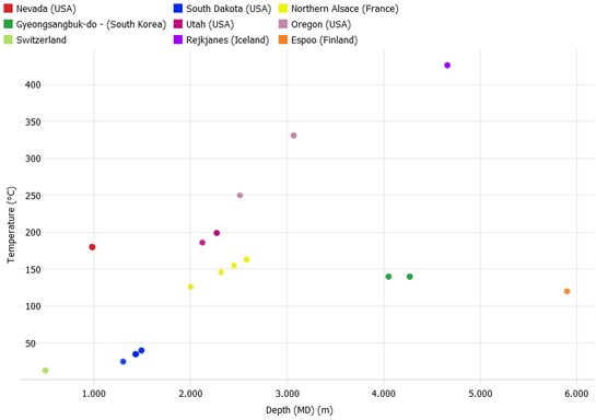
EGS projects are spread around the world. Fig. 17 indicates the target depth and the temperature reached the target depth. The trend of higher temperatures with the increase in depth can be seen. Nevertheless, there are two outliers in Finland and South Korea.
In the following summary, a description of EGS projects around the world that included one or more stimulation types or procedures and ordered by location is presented.
Fig. 17The highest temperature of the investigated projects 426 °C was reached in Iceland at a depth of 4,550 meters. The average depth of the wells is about 2,500 m with a temperature of about 175 °C
5.1. Desert peak – USA
Well 27-15 of the Desert Peak geothermal field in Nevada was a proper candidate for fracturing as its performance as an injector or a producer had been dissatisfactory from the beginning. Nevertheless, due to its desirable downhole temperatures (up to 190 °C) and the existing surface facilities, fracturing operations were executed to reach several goals, including the development of a site-specific fracturing plan showcasing the most practical and economical techniques, as well as investigating the possible merits of power generation from the entire EGS project. Supported by the Department of Energy, the stimulation plan, conducted between 2010 and 2011, consisting of multiple stages, including multiple low-pressure shear stimulation phases, two stages of chemical stimulation. Finally, an extensive phase of hydraulic fracturing at high pressures concluded the program. The target was to investigate whether or not the injectivity of well 27-15 reaches the commercially accepted limit in the Desert Peak. This target was achieved and as a result of the stimulation, the injectivity of well 27-15 increased by a factor of 60 and confirmed via the tracer test. It was also observed that the main shear stimulation success was in the early stages of the program, suggesting that a shorter program at higher injection pressures could potentially offer similar results. Additionally, it was observed that chemical stimulation tends to have better efficiency when used solely to improve an existing network of fractures, meaning that using chemicals for fracture initiation can lead to accumulation of the fluid in the near-wellbore region and as a result costly operations [96].
5.2. Raft river – USA
Another successful fracturing job was performed in Raft River, Idaho, as part of the demonstration projects of the Department of Energy. The Raft River site includes four injectors and four producers, and the well RRG-9 ST1 as the newest injector was stimulated using a combination of hydraulic and thermal methods. The hydraulic stimulation plan began in 2012, followed by a year and a half of shut-in period to construct proper surface pipelines connecting to the wellhead. The well was then stimulated twice in the following years with periods of shut-in and regular cold water injection. By the end of the fracturing operation, the result of the modified Hall plot as well as the increase in injectivity confirmed the success of the fracturing job [97], [98].
5.3. Newberry – USA
The Newberry EGS demonstration project began in 2010 and was funded by the Department of Energy in the USA. Located in the area of a volcano in central Oregon, the well NWG 55-29 was originally drilled in 2008 to a depth of 3,067 m, encountering temperatures of about 331 °C. After the approval for the funding and 2 years of development and planning, the well underwent the first round of stimulation in 2012, which led to damages of the casing. After installing a tie-back over the damaged zone and conducting further remediations, the well was stimulated once again in 2014 in the form of hydraulic shearing. The overall outcome was an increase in the permeability as well as the volume of fractures in the microcrystalline granodiorite reservoir, with a five-fold injectivity increase. In this stimulation process, a special component called TZIM (Thermally-degradable Zonal Isolation Material) was used. The material is made of components that degrade without any environmental harm within a certain temperature range. After implementation, it was evident that two thief zones were blocked and one or two new zones were opened as a result of using TZIM. Seismic monitoring was performed continuously to provide a clear understanding of injection limits. The partner well 55A-29 was drilled in 2014 to act as the production well of the doublet [99].
5.4. Rittershofen – France
The ECOGI is the first EGS project in France to produce water from geothermal reservoirs in the Upper Rhine Graben. The project location is in Rittershofen, about 6 km east of the well-known Soultz-sous-Forets EGS. Initiated in 2004, the feasibility study concluded in 2011 and the first well GRT-1 was drilled between September and December 2012 to a depth of 2,580 m MD into a granite formation. The second well GRT-2 was then drilled between May and July 2014 to a depth of 3,196 m MD to be the producer. Stimulation in GRT-1 was conducted in three phases: 1) a thermal stimulation, 2) a chemical stimulation followed by 3) a hydraulic stimulation. The environmentally friendly acids based on Glutamate were used in phase two to dissolve the minerals that seal the natural fractures. The job was deemed successful and the wells were later put into operation [100].
5.5. Otaniemi – Finland
Otaniemi is the geothermal doublet project developed in Espoo, Finland, in the vicinity of Helsinki for district heating purposes. Being the deepest EGS project to date, the main wellbore OTN-3 was drilled to a depth of 6.4 km in 2018, reaching temperatures of about 120 °C. A 10 m offset well, OTN-2, was also drilled to 3.3 km for monitoring purposes, which was planned to also be extended in 2019 to 6.1 km. The wells are almost entirely in a granite and pegmatite formation and have therefore been drilled using air and water hammer drilling mechanisms, together with rotary systems for better steering. OTN-3 was hydraulically fractured later in 2018 for 49 days and in five phases each with different injection pressures. Since the project is located underneath a largely populated area, even a slight chance of seismic activity can not only be dangerous but also affect the positive image of the project in the public’s eyes. Therefore, a TLS (Traffic Light System) was developed for the monitoring of seismic activities that could assist the mitigation and define the steps to be taken under various circumstances. The system can define the limits of pumping power, pressure as well as the shut-in time between the different stages of stimulation [101]-[103].
5.6. DEEPEGS – Iceland
The Iceland Deep Drilling Project (IDDP) was kicked off in 2000. After years of study and planning, the first drilling project was meant to start in Rejkyanes geothermal field located in the southwest of Iceland in 2005. Yet, the deepening of some existing wells hit several issues, persuading the team to choose another location in the northeast of Iceland for drilling the IDDP-1. The well could not reach supercritical conditions as it hit a magma layer at only 2,100 m, with fluid pressures and temperatures lower than expected. After two successful years of operation, and for maintenance reasons, the well had to be quenched, which led to its collapse and eventually its abandonment [105]. The exploration well IDDP-2 was therefore drilled and completed in 2017 as part of the DEEPEGS demonstration project conducted by Iceland and France and funded by the EU Horizon 2020. The final depth of the well was 4,650 m, and although expected to reach supercritical temperatures up to 600 °C, the recorded temperature after six days of heating at 4,550 m was 426 °C. Among the problems faced during drilling was a complete lost circulation at depths below 3.2 km despite which the drilling continued. The formation rock at that depth consisted of micro-dolerites with basalt. During the drilling process and for over a year after, cold water was injected not only to cool down the equipment but also to enhance the permeability in the near-wellbore region through thermal stimulation. The total volume of injected water was therefore in the range of 1.5-2 million tons, reaching a final injectivity value of 2.7-2.9 l/s/bar [105], [106].
5.7. Pohang – South Korea
The project in Pohang was the first EGS developed in South Korea and was kicked off in 2010. Wellbore PX-1 with 4,127 m depth and PX-2 with 4,348 m depth were drilled to be stimulated and used together with a third wellbore to create a triplet system. The reservoir was made of granodiorite and granitic gneiss with temperatures reaching 140 °C. PX-2 was the first well to be stimulated in 2016. After three stages of hydraulic fracturing lasting until 2017, the injectivity of the reservoir increased by 2.7 times. Shortly after the start of fracturing in PX-2, hydraulic shearing was conducted in PX-1. Stimulation in this well also led an almost twice the injectivity index [107], [108]. The further development was put to rest after a 5.4 magnitude earthquake happened in the location in November 2017, two months after the last stimulation took place. This was the second-largest earthquake to have ever happened in South Korea. It caused injuries to 90 people and the estimated property damage was about $52 million. A further study investigated the relationship between seismic activities after each injection. Based on that, and the lack of any other activity before the operation of the EGS, it was proven that the stimulation operations were the reason behind the earthquake [109], [110].
Fig. 18 shows the increase in breakdown pressure with minimum horizontal stress for the field cases and confirms the finding of the laboratory tests. Typically, the minimum horizontal stress is in the range of 20 to 40 MPa, resulting in formation breakdown pressures of 20 to 40 MPa too.
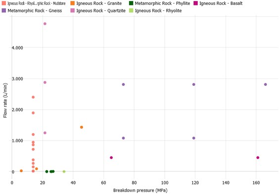
The trend of the increase in formation breakdown pressure by the increase in injection rate, also for field cases, is shown in Fig. 19. Nevertheless, other factors, like natural internal rock structure, fluid type, etc. that influence the formation breakdown pressure were not found and therefore no general statement can be made.
6. Recent and planned EGS projects
Several EGS projects have been recently initiated. The wellbores have been drilled already or are planned to be drilled in the near future.
Fig. 18Formation breakdown pressure versus minimum horizontal stress
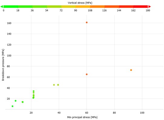
Fig. 19There is an outlier with a formation breakdown pressure of 160 MPa at minimum horizontal stress of 60 MPa and an injection rate of about 3,000 l/min for the Rejkyanes geothermal field in Iceland
6.1. Schneeberg – Germany
In Saxony (Germany), a project is aimed to be carried out in crystalline rocks, in particular granite and phyllite. A roadmap has been created by 2015 in a collaboration between multiple companies and universities, with the support of the German Federal Ministry. The initial goal is to drill a wellbore “Schneeberg 1” to acquire geological and reservoir data. The wellbore is expected to be drilled to 5250 m MD (5000 m TVD), crossing the fault system Rote Kamm at 2000 m. Temperature experienced at this depth would be between 180 °C and 200 °C. The borehole should be capable of producing 30 gallons/s [111].
6.2. SHEGS – Hungary
The South Hungarian EGS (SHEGS) is a demonstration project in south-eastern Hungary, funded by the Hungarian Ministry of Economy. The project includes four production wells with an approximate depth of 4 km each, and two re-injection wells, all connected to a power plant with an estimated capacity of 8.9 MWe. The reservoir is composed of granitoid rocks and the overall thermal gradient ranges between 55-65 °C/km. Seismic activities are planned to be closely monitored to avoid any issues for the population as well as the available infrastructure [112]. The drilling was aimed to start in 2016. However, the project is still not in operation and no further information was provided.
6.3. Qiabuqia – China
Despite the existence of vast geothermal resources in China, they only recently started to gain more popularity. These resources are estimated to be equivalent to 860 million tons of standard coal, which can support China’s energy needs for the next 3,945 years even at a 2 % exploitation rate. As a result, the first demonstration project in China was established in Qiabuqia geothermal field in the northwest of China. Ten exploration wellbores were drilled on the site, with many reaching temperatures as high as 178 °C. Well GR1 was, particularly of interest. It was drilled to 3,705 m in 2017, reaching a stable temperature of 236 °C after five months of a shut-in. Nevertheless, based on the stress state of the surrounding granite formation and the existence of natural fractures, the pay zone was selected to be between 3,200 and 3,705 m, with a temperature of 218 °C. To achieve better flow rates, multiple stimulation scenarios were modeled, concluding that hydraulic fracturing is the best approach for future planning [113].
6.4. DEEPEGS – France
The DEEPEGS project was conducted as a collaboration between Iceland and France. While the project aimed for the development of high-enthalpy EGS with supercritical pressure and temperature in Iceland, it aimed to explore the geothermal capacities in hydrothermal reservoirs in southern France in Valence and Vistrenque. Due to lack of public acceptance in Valence, a secondary location was chosen in Riom, in central France. Yet, the planning and acquisition of permits hit a dead end, and eventually, the project team decided to replace the two target projects with a geothermally rich site in Vendenheim [114]. The second demonstrator wells in Vendenheim were therefore drilled in 2019 as a doublet and tested in 2020. The wells reach the Upper-Rhine-Graben at depths of 5,308 m and 5,393 m and temperatures of 200 °C. Since the measured injectivity of the zone is below the intended value, thermal stimulations are considered for future steps [105].
6.5. BULG - Switzerland
The BULG is an ETH facility in a 100 m long cavern at depths between 1,000 to 1,200 m, with temperatures reaching a steady value of 17 °C. Site characterization was conducted in 2018 and experiments are expected to begin in 2020 with several project partners. The rock type is the particular Rotondo Granite. The depth, location, and stress regime of this test site are superior to GTS in terms of similarity to an actual EGS project [94], [115].
7. Projects with potential for stimulation
There exist projects around the world where the producing reservoirs have acceptable ranges of permeability, either due to the coarse rock type or due to existing natural fractures. In all projects, however, there is potential for future stimulations in case the permeability declines with time. Some of these projects are mentioned in the section.
7.1. United Downs – UK
The United Downs project is the first geothermal power project in the UK. It is located in the west of Cornwall and is consisted of a production well with a depth of 4,500 m and an injection well with a depth of 2,500 m. The formation rock is mainly granitic and has an approximate temperature of 190 C. The aim is to generate 1-3 MWe electricity from this field. Drilling and completion of the wells were planned to be completed in 2019. Since the reservoir is naturally fractured, with a shearing onset of 5 MPa, no fracking procedure is foreseen at the moment but could become necessary in the years to come. It is expected that a normal injection of water can support the pressure requirements. The success of this project can pave the way for future geothermal projects in the area and fulfill the goal of generating the country’s electricity from renewable sources by 2030 [116].
7.2. Eden – UK
Eden geothermal demonstration project aims to recover energy from the naturally fractured granite formation beneath the city of Cornwall. Initially, production will be through a coaxial circulation in one well with an approximate depth of 4.5 km. The energy is supposed to be captured and used for heating greenhouses and offices in the area. In phase two of the project, a second well will be drilled to the same depth, converting the system into a geothermal doublet and connecting it to an electric power plant. The first well EG1 will be drilled in Spring 2021 after some delays, using conventional rotary drilling. Since the reservoir is naturally fractured, no stimulation is foreseen at the moment but could be a possibility subject to future production trends [117].
7.3. Mauerstetten – Germany
To investigate the geothermal potential in the Western Bavarian Molasse Basin, a geothermal well was drilled together with a side-track close to a fault system. The main well, GT1 was drilled to 4,523 m MD (4,085 m TVD) and the side-track GT1a to 4,052 m MD (3572 TVD) with a lateral distance of 513 m to GT1 in 289-degree azimuth. Because porosity generation by recrystallization is a slow process, natural fractures are considered the main network for fluid flow. Nevertheless, the calcite fillings of such fractures had reduced the transmissivity of the fractures. Therefore, an acid stimulation plan with HCl pills was already conducted. Based on the results, a future stimulation plan can be prepared, however, no further data is available at this point [118].
8. Comparison of lab and field observations
In the laboratory, the fracture propagation detection is done visually, by 3D and CT scans, microscopic images, NMR, acoustic emissions, and pressure response. In the field, most of these detection methods cannot be applied. Typically, acoustic emission and pressure response monitoring is performed. Especially in the field research projects separate monitoring wells are drilled to detect the fracture propagation. In most of the EGS projects in the field, water has been used as stimulation fluid, in some cases acid. In the lab, most experiments on hydraulic stimulations used water or slickwater. In contrast, the laboratory tests related to tight oil and gas production widely follow the scaling laws and use higher viscous fluids, like guar gum or oil.
The comparison of the formation breakdown pressure of the field research projects and the field operation projects shows in general a lower fluid injection rate for the research projects. In general, the formation breakdown pressure is just partially influenced by the fluid injection rate (Fig. 20).
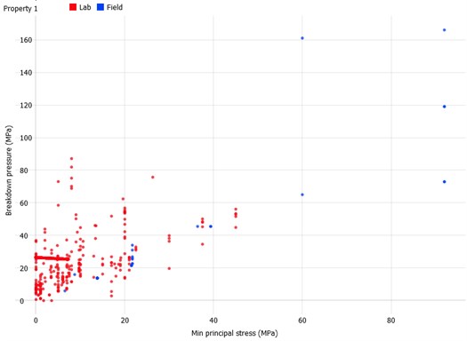
The comparison of the formation breakdown pressure for the laboratory tests and the field projects is shown in Fig. 21. In general, the tendency is similar. The increase in minimum horizontal stress increases the formation breakdown pressure. In the laboratory various rock types, having a different internal structure, like bedding planes or natural fractures, have been tested and a significant number of tests, using high viscous fluid resulted in an over proportional high formation breakdown pressure.
Fig. 20Formation breakdown pressure versus flow rate for the field research and field operation projects
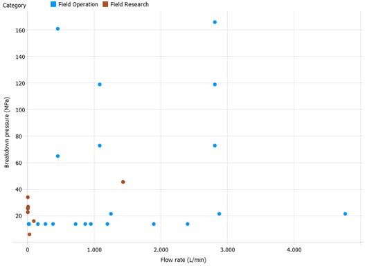
Fig. 21Fracture propagation pressure versus Minimum Horizontal Stress for lab experiments (red) and field projects (blue)
9. Conclusions
This paper reviewed a great number of research works as well as real-field projects to provide a summary of know-how in the field of hydraulic fracturing. Based on the gathered data, reservoir in-situ stress and in particular minimum horizontal stress, fracture initiation pressure and injection pressure and flow rate are the main variables from one rock type to the other, when it comes to creating new fractures. Generally speaking, the harder the rock material and the deeper the reservoir, the higher the stress fields and the required injection pressure and flow rate. Typical outliers exist in specific or artificially made rock material, as well as fields with exceptionally high geothermal gradient.
This work also managed to align the lab experiment results with those achieved in the field, indicating that a prior in-depth study of the formations, will surely provide valuable expertise for actual field operations. An additional measure is the control and monitoring techniques to visualize the fractures’ state as well as mitigating any unfavorable outcome that can affect the environment. When implemented altogether, an operation with minimum risk and maximum gain can be easily expected.
References
-
C. Langbauer, G. Jax, P. Vita, and H. Hofstätter, “Hydraulic concentric tubular pumping system for lifting oil in EOR completions,” SPE EOR Conference at Oil and Gas West Asia, 26-28 March, Muscat, Oman, 2018, SPE-190344-MS, https://doi.org/10.2118/190344-MS
-
C. Langbauer, E. Chevelcha, and H. Hofstätter, “Buckling prevention using the tensioning device,” SPE Artificial Lift Conference-Americas, 21-22 May, Cartagena, Colombia, 2013, SPE-165013, https://doi.org/10.2118/165013-MS
-
E. Chevelcha, C. Langbauer, and H. Hofstätter, “Listening sucker rod pumps: stroke’s signature,” SPE Artificial Lift Conference-Americas, 21-22 May, Cartagena, Colombia, 2013, SPE-165035-MS, https://doi.org /10.2118/165035-MS
-
D. Kochtik and C. Langbauer, “Volumetric efficiency evaluation of sucker rod-pumping applications performed on a pump testing facility,” SPE Middle East Artificial Lift Conference and Exhibition, 28-29 November, Manama, Bahrain, 2018, SPE-192454-MS, https://doi.org/10.2118/192454-MS
-
C. Langbauer, M. Hartl, S. Gall, L. Volker, D. Decker, L. Koller, and H. Hönig, “Development and efficiency testing of sucker rod pump downhole desanders,” SPE Production and Operations, SPE-200478-PA, January 2020, https://doi.org/10.2118/200478-PA
-
C. Langbauer, “Sucker Rod Anti-Buckling system Analysis,” Ph.D. Thesis, Montanuniversitaet Leoben, 2015.
-
C. Langbauer, F. Fruhwirth, M. Hartl, and H. Hofstätter, “Sucker rod anti-buckling system to enable cost-effective oil production,” SPE Asia Pacific Oil and Gas Conference and Exhibition, 23-25 October, Brisbane, Australia, 2018, SPE-191865-MS, https://doi.org/10.2118/191865-MS
-
C. Langbauer and G. Kaserer, “Industrial application of a linear drive system in a pump testing facility,” 17th International Ural Conference on AC Electric Drives (ACED), 26-30 March 2018, IEEE Ekaterinburg, Russia, https://doi.org/10.1109/ACED.2018.8341726
-
C. Langbauer and F. Fazeli-Tehrani, “Pump test facility for research, testing, training, and teaching,” Erdöl Erdgas Kohle Magazin, Vol. 135, No. 7/8, pp. 35–42, 2020.
-
C. J. De Pater, M. P. Cleary, and T. S. Quinn et al., “Experimental Verification of Dimensional Analysis for Hydraulic Fracturing,” SPE Paper No. 24994, SPE Production and Facilities, pp. 230–238, 1994, https://doi.org/10.2118/24994-PA
-
S. H. Fallahzadeh, V. Rasouli, and M. Sarmadivaleh, M., “An investigation of hydraulic fracturing initiation and near-wellbore propagation from perforated boreholes in tight formations,” Rock Mechanics and Rock Engineering, Vol. 48, No. 2, pp. 573–584, 2015.
-
T. P. Lhomme, C. J. De Pater, and P. H. Helfferich, “Experimental study of hydraulic fracture initiation in Colton sandstone,” Proceedings of the SPE/ISRM Rock Mechanics Conference, Society of Petroleum Engineers, Nancy, France, February 2002.
-
A. P. Bunger, R. G. Jeffrey, and E. Detournay, “Application of Scaling Laws to Laboratory-Scale Hydraulic Fractures.” ARMA/USRMS Paper No.05-818, Prepared for presentation at the 40th US symposium on Rock Mechanics (USRMS): Rock Mechanics for Energy, Mineral and Infrastructure Development in the Northern Regions, 2005.
-
M. G. Mack, N. Warpinski, “Mechanics of hydraulic fracturing, Reservoir Stimulation,” 2000.
-
E. Detournay, “Propagation Regimes of fluid-driven fractures in impermeable rocks,” International Journal of Geomechanics, 2004, https://doi.org/10.1061/(ASCE)1532-3641(2004)4:1(35)
-
M. D. Zoback, et al., “Laboratory hydraulic fracturing experiments in intact and pre-fractured rock” International Journal of Rock Mechanics and Mining Sciences & Geomechanics Abstracts, 1977, https://doi.org/10.1016/0148-9062(77)90196-6
-
Y. Qian, et al., “Advances in Laboratory-Scale Hydraulic Fracturing Experiments,” Advances in Civil Engineering, Vol. 2020, p. 1386581, 2020, https://doi.org/10.1155/2020/1386581
-
L. J. Beugelsdijk, C. J. De Pater, and K. Sato, “Experimental hydraulic fracture propagation in a multi-fractured medium,” in SPE Asia Pacific Conference on Integrated Modelling for Asset Management, Yokohama, Japan, April 2000, https://doi.org/10.2118/59419-MS
-
R. J. Weimer, and R. W Tillman, “Sandstone reservoirs,” in International Petroleum Exhibition and Technical Symposium, Beijing, China, 1982, https://doi.org/10.2118/10009-MS
-
C. J. De Pater, Y. Dong, and B. Bohloli, “Experimental Study of Hydraulic Fracturing in Sand as a Function of Stress and Fluid Rheology,” in SPE Hydraulic Fracturing Technology Conference, College Station, Texas, U.S.A., 2007, https://doi.org/10.2118/105620-MS
-
B. Bohloli, and C. J. De Pater, “Experimental study on hydraulic fracturing of soft Rocks: Influence of fluid rheology and confining stress,” Journal of Petroleum Science and Engineering, Vol. 53, No. 1-2, pp. 1–12, 2006, https://doi.org/10.1016/j.petrol.2006.01.009
-
J. E. Olson, J. Holder, and S. Mehran Hosseini, “Soft rock fracturing geometry and failure mode in lab experiments,” in SPE Hydraulic Fracturing Technology Conference, The Woodlands, Texas, USA, 2011, https://doi.org/10.2118/140543-MS
-
A. N. Dehghan, K. Goshtasbi, and K. Ahangari et al., “Experimental investigation of hydraulic fracture propagation in fractured blocks,“ Bulletin of Engineering Geology and the Environment, Vol. 74, pp. 887–895, 2015, https://doi.org/10.1007/s10064-014-0665-x
-
Y. Chen, Y. Nagaya, and T. Ishida, „Observations of fractures induced by hydraulic fracturing in anisotropic granite, “Rock Mechanics and Rock Engineering, Vol. 48, pp. 1455–1461, 2015, https://doi.org/10.1007/s00603-015-0727-9
-
R. Zhang, et al., “Hydraulic fracturing initiation and near-wellbore nonplanar propagation from horizontal perforated boreholes in tight formation,” Journal of Natural Gas Science and Engineering, Vol. 55, pp. 337–349, 2018, https://doi.org/10.1016/j.jngse.2018.05.021
-
F. Tie-gang, and G. Zhang, “Laboratory investigation of hydraulic fracture networks in formations with continuous orthogonal fractures,” Energy, Vol. 74, pp. 164–173, 2014, https://doi.org/10.1016/j.energy.2014.05.037
-
J. Zhou, et al., “Analysis of fracture propagation behaviour and fracture geometry using a tri-axial fracturing system in naturally fractured reservoirs,” International Journal of Rock Mechanics and Mining Sciences, Vol. 45, No. 7, pp. 1143–1152, 2008, https://doi.org/10.1016/j.ijrmms.2008.01.001
-
Z. Zhou, et al., “Creating a network of hydraulic fractures by cyclic pumping,” International Journal of Rock Mechanics and Mining Sciences, 2017, https://10.1016/j.ijrmms.2017.06.009
-
S. V. Gosavi, et al., “Advanced fracture modelling: lab experiments to field applications,” in Abu Dhabi International Petroleum Exhibition & Conference, Abu Dhabi, UAE, 2017, https://doi.org/10.2118/188891-MS
-
C. M. Kim and H. H. Abass, “Hydraulic fracture initiation from horizontal wellbores: laboratory experiments,” in 32nd U.S. Symposium on Rock Mechanics (USRMS), Norman, Oklahoma, 1991.
-
C.J. De Pater, et al., “Experimental Study of Nonlinear Effects in Hydraulic Fracture Propagation (includes associated papers 29225 and 29687),” SPE Production and Facilities, Vol. 9, No. 4, pp. 239–246, 1994, https://doi.org/10.2118/25893-PA
-
L. A. Behrmann and J. L. Elbel, “Effect of Perforations on Fracture Initiation,” Journal of Petroleum Technology, Vol. 43, pp. 608–615, 1991, https://doi.org/10.2118/20661-PA
-
A. S. Athavale and J. L. Miskimins, “Laboratory Hydraulic Fracturing Tests on Small Homogeneous and Laminated Blocks,” in 42nd U.S. Rock Mechanics Symposium (USRMS), San Francisco, California, 2008.
-
A. P. Bunger, et al., “Laboratory Investigation of Hydraulic Fracture Growth Through Weak Discontinuities with Active Ultrasound Monitoring,” in 13th ISRM International Congress of Rock Mechanics, Montreal, Canada, 2015.
-
G. D. Anderson, “Effects of friction on hydraulic fracture growth near unbonded interfaces in rocks,” SPE Journal, Vol. 21, pp. 21–29, 1981, https://doi.org/10.2118/8347-PA
-
N. R. Warpinski, et al., “Laboratory investigation on the – effect of in-situ stresses on hydraulic fracture containment,” SPE Journal, Vol. 22, pp. 333–340, 1982, https://doi.org/10.2118/9834-PA
-
Y. Zou, et al., “Experimental study on the growth behaviour of supercritical CO2-induced fractures in a layered tight sandstone formation,” Journal of Natural Gas Science and Engineering, Vol. 49, pp. 145-156, 2018, https://doi.org/10.1016/j.jngse.2017.11.005
-
S. Patel, C. Sondergeld, and C. S. Rai, “Laboratory studies of hydraulic fracturing by cyclic injection,” International Journal of Rock Mechanics and Mining Sciences, Vol. 95. 2017, https://doi.org/10.1016/j.ijrmms.2017.03.008
-
Y. Lou, G. Zhang, and X. Wang, “Study on fracture mechanism of hydraulic fracturing in sandstone by acoustic emission parameters,” Procedia Engineering, Vol. 191, pp. 291–298, 2017, https://doi.org/10.1016/j.proeng.2017.05.184
-
F. Stoeckhert, et al., “Fracture propagation in sandstone and slate – laboratory experiments, acoustic emissions and fracture mechanics,” Journal of Rock Mechanics and Geotechnical Engineering, Vol. 7, No. 3, pp. 237–249, 2015, https://doi.org/10.1016/j.jrmge.2015.03.011
-
A. A. Daneshy, “Hydraulic Fracture Propagation in Layered Formations,” SPE Journal, Vol. 18, pp. 33–41, 1978, https://doi.org/10.2118/6088-PA
-
F. Stoeckhert, C. Solibida, and M. Alber, “Hydraulic fractures in discontinuous, anisotropic and heterogeneous rock - a lab study,” in ISRM International Symposium – EUROCK 2020, 2020.
-
L. A. Casas, et al., “Laboratory hydraulic fracturing test on a rock with artificial discontinuities,” in SPE Annual Technical Conference and Exhibition, San Antonio, Texas, USA, 2006, https://doi.org/10.2118/103617-MS
-
H. Jianming, et al., “Initiation, propagation, closure, and morphology of hydraulic fractures in sandstone cores,” Fuel, Vol. 208, pp. 65–70, 2006, https://doi.org/10.1016/j.fuel.2017.06.080
-
S. Brenne, et al., “Hydraulic and sleeve fracturing laboratory experiments on 6 rock types,” Proceedings of the International Conference for Effective and Sustainable Hydraulic Fracturing, Brisbane, Australia, 2013, https://doi.org/10.5772/56301
-
S. Stanislawek, P. Kędzierski, and D. Miedzińska, “Laboratory hydraulic fracturing tests of rock samples with water, carbon dioxide, and slickwater,” Archives of Civil Engineering, 2017, https://doi.org/10.1515/ace-2017-0033
-
B. Hou, et al., “Investigation on acid fracturing treatment in limestone formation based on true tri-axial experiment,” Fuel, Vol. 235, pp. 473–484, 2019, https://doi.org/10.1016/j.fuel.2018.08.057
-
L. Baohua, J. Yan, and C. Mian, “Influence of vugs in fractured-vuggy carbonate reservoirs on hydraulic fracture propagation based on laboratory experiments,” Journal of Structural Geology, Vol. 124, pp. 143–150, 2019, https://doi.org/10.1016/j.jsg.2019.04.007
-
D. Wei, et al., “Experimental hydraulic fracture propagation on naturally tight intra-platform shoal carbonate,” Journal of Petroleum Science and Engineering, Vol. 157, pp. 980–989, 2017, https://doi.org/10.1016/j.petrol.2017.08.016
-
W. Cheng, Y. Jin, and M. Chen, “Reactivation mechanism of natural fractures by hydraulic fracturing in naturally fractured shale reservoirs,” Journal of Natural Gas Science and Engineering, Vol. 23, pp. 431–439, 2015, https://doi.org/10.1016/j.jngse.2015.01.031
-
T. Guo, et al., “Experimental study of hydraulic fracturing for shale by stimulated reservoir volume,” Fuel, Vol. 128, pp. 373–380, 2014, https://doi.org/10.1016/j.fuel.2014.03.029
-
S. Heng, et al., “Experimental and numerical study on the non-planar propagation of hydraulic fractures in shale,” Journal of Petroleum Science and Engineering, Vol. 179, pp. 410–426, 2019, https://doi.org/10.1016/j.petrol.2019.04.054
-
B. Hou, et al., “Analysis of hydraulic fracture initiation and propagation in deep shale formation with high horizontal stress difference,” Journal of Petroleum Science and Engineering, Vol. 170, pp. 231–243, 2018, https://doi.org/10.1016/j.petrol.2018.06.060
-
J. Kear, et al., “2D Experimental and Numerical Results for Hydraulic Fractures Interacting with Orthogonal and Inclined Discontinuities,” 51st US Rock Mechanics / Geomechanics Symposium, 2017.
-
X. Ma, et al., “Hydraulic fracture propagation geometry and acoustic emission interpretation: a case study of Silurian long maxi formation shale in Sichuan Basin, SW China,” Petroleum Exploration and Development, Vol. 44, No. 6, pp. 1030–1037, 2017, https://doi.org/10.1016/S1876-3804(17)30116-7
-
R. Zhang, et al., “Experimental investigation on fracture morphology in laminated shale formation by hydraulic fracturing,” Journal of Petroleum Science and Engineering, Vol. 177, pp. 442–451, 2019, https://doi.org/10.1016/j.petrol.2019.02.056
-
G. D. Alderton and S. A. Elias, “Encyclopedia of Geology,” Elsevier, 2021.
-
Y. Cheng and Y. Zhang, “Hydraulic fracturing experiment investigation for the application of geothermal energy extraction,” ACS Omega, Vol. 5, No. 15, pp. 8667–8686, 2015, https://doi.org/10.1021/acsomega.0c00172
-
S. L. Craig, “A Study of fracturing and heat Transfer in Enhanced Geothermal Systems,” Ph.D. Thesis, University of Utah, 2016.
-
P. Deb, et al., “Laboratory experiments and numerical simulations of hydraulic fracturing for enhanced geothermal systems,” European Geothermal Congress, Den Haag, The Netherlands, 2019.
-
M. Diaz, et al., “Hydraulic, mechanical, and seismic observations during hydraulic fracturing by cyclic injection on Pocheon granite,” in ISRM International Symposium – 10th Asian Rock Mechanics Symposium, Singapore, 2018.
-
L. P. Frash, “Laboratory scale study of hydraulic fracturing in heterogeneous media for enhanced geothermal systems and general well stimulation,” Ph.D. Thesis, Colorado School of Mines, 2014.
-
J. Hampton, et al., “Acoustic emission characterization of microcracking in laboratory-scale hydraulic fracturing tests,” Journal of Rock Mechanics and Geotechnical Engineering, Vol. 10, No. 5, pp. 805–817, 2018, https://doi.org/10.1016/j.jrmge.2018.03.007
-
L. Hu, et al., “Laboratory scale investigation of enhanced geothermal reservoir stimulation,” ARMA 16-258, American Rock Mechanics Association, 2016.
-
L. Hu, et al., “Characterization of laboratory-scale hydraulic fracturing for EGS,” Geothermics, Vol. 83, 2019, https://doi.org/10.1016/j.geothermics.2019.07.004
-
T. Ishida, et al., “Acoustic emission monitoring of hydraulic fracturing laboratory experiment with supercritical and liquid CO2,” Geophysical Research Letters, Vol. 39, No. 16, 2012, https://doi:10.1029/2012GL052788
-
L. Jia, et al., “Experimental study on propagation of hydraulic fracture in volcanic rocks using industrial CT technology,” Petroleum Exploration, and Development, Vol. 40, No. 3, pp. 405–408, 2013, https://doi.org/10.1016/S1876-3804(13)60051-8
-
H. Jianming, et al., “Experimental Investigation of Crack Extension Patterns in Hydraulic Fracturing with Shale, Sandstone and Granite Cores,” Energies, Vol. 9, No. 12, pp. 1–16, 2012.
-
P. Siebert, et al.,“Hydraulic fracturing of large igneous rock samples under triaxial compression,” in 13th ISRM International Congress of Rock Mechanics, Montreal, Canada, 2015.
-
P. Siebert, “Laboratory tests on hydraulic crack generation in triaxially loaded granite ashlars - fundamentals, test development, execution and analysis,” Ph.D. Thesis, Rheinisch-Westfälischen Technischen Hochschule Aachen, 2017, (in German).
-
Y. Xing, et al., “Hydraulic fracturing in high-temperature granite characterized by acoustic emission,” Journal of Petroleum Science and Engineering, Vol. 178, pp. 475–484, 2019, https://doi.org.10.1016/j.petrol.2019.03.050
-
Z. Zhou, et al., “Experimental study of hydraulic fracturing in enhanced geothermal system,” in 52nd U.S. Rock Mechanics/Geomechanics Symposium, Seattle, Washington, 2018.
-
L. Zhuang, et al., “Laboratory true triaxial hydraulic fracturing of granite under six fluid injection schemes and grain-scale fracture observations,” Rock Mechanics and Rock Engineering, Vol. 53, 2020, https://doi.org/10.1007/s00603-020-02170-8
-
B. Gonçalves da Silva, et al., “Development of a test setup capable of producing hydraulic fracturing in the laboratory with image and acoustic emission monitoring,” 49th US Rock Mechanics / Geomechanics Symposium, 2019.
-
P. Solberg, D. Lockner, J. D. Byerlee, “Hydraulic fracturing in granite under geothermal conditions,” International Journal Rock Mechanics and Mining Science Abstracts, Vol. 17, No. 1, pp. 25–33, 1980.
-
S. Inui, et al., “AE monitoring of hydraulic fracturing experiments in granite blocks using supercritical CO2, water, and viscous oil,” Proceedings of ARMA 2014, Paper No. ARMA 14-7163, Minneapolis, USA, 2014.
-
T. Ishida, et al., “AE monitoring of hydraulic fracturing laboratory Experiments conducted using CO2 and water,” Proc Eurock 2013, pp. 957–962, 2013.
-
Y. Lu, “Laboratory Studies on thermal fracturing behaviour in well stimulation of enhanced geothermal systems,” Master Thesis, Texas A&M University, 2017.
-
D. Lockner, “The role of acoustic emission in the study of rock fracture,” International Journal of Rock Mechanics and Mining Sciences & Geomechanics, Vol. 30, No. 7, pp. 883–899, 1993.
-
Y. Cheng, et al., “An investigation on hydraulic fracturing characteristics in granite geothermal reservoir,” Engineering Fracture Mechanics, Vol. 237, 2020, https://doi.org/10.1016/j.engfracmech.2020.107252
-
A. Zang, et al., “Fatigue hydraulic fracturing by cyclic reservoir treatment enhances permeability and reduces induced seismicity,” Geophysical Journal International, Vol. 195, No. 2, pp. 1282–1287, 2013.
-
A. Zang, et al., “Source analysis of acoustic emissions in Aue granite cores under symmetric and asymmetric compressive loads,” Geophysical Journal International, Vol. 135, pp. 1113–1130, 1998.
-
A. Zang, S. Stanchits, and G. Dresen, “Acoustic emission controlled triaxial rock fracture and friction tests,” Structural Integrity and Fracture, pp. 289–294, 2002.
-
P. Deb, et al., “Laboratory-scale hydraulic fracturing dataset for benchmarking of enhanced geothermal system simulation tools,” Scientific Data, Vol. 7, No. 1, 2020, doi.org/10.1038/s41597-020-0564-x
-
M. Smith, et al., “High-temperature laboratory experiments to support EGS stimulations: permeability response in fractured crystalline samples,” 43rd Workshop on Geothermal Reservoir Engineering, Stanford University, Stanford, California, SGP-TR-213, 2018.
-
L. Zhuang, et al., “Modelling rock fracturing processes – laboratory investigations on the hydraulic fracturing of granite cores,” Springer Netherlands, 2014, https://doi.org/10.1007/978-94-007-6904-5
-
C. Oldenburg, et al., “Hydraulic fracturing experiments at 1500 m depth in a deep mine: Highlights from the kISMET project,” in 42nd Workshop on Geothermal Reservoir Engineering, 2020, https://escholarship.org/uc/item/3415c3dh
-
T. J. Kneafsey, et al., “EGS Collab Project: Status, Tests, and Data,” 53rd U.S. Rock Mechanics/Geomechanics Symposium, 2019, https://onepetro.org/ARMAUSRMS/proceedings-abstract/ARMA19/All-ARMA19/ARMA-2019-2004/125109
-
M. D. Ingraham, et al., “Analysis of hydraulic fracturing on the 4100 level at the sanford underground research facility,” 54th U.S. Rock Mechanics/Geomechanics Symposium, 2020, https://onepetro.org/ARMAUSRMS/proceedings-abstract/ARMA20/All-ARMA20/ARMA-2020-1158/447479
-
T. J. Kneafsey, et al., “The EGS Collab Project: Stimulation and Simulation,” 52nd U.S. Rock Mechanics/Geomechanics Symposium, 2018, https://onepetro.org/ARMAUSRMS/proceedings-abstract/ARMA18/All-ARMA18/ARMA-2018-1345/122351
-
S. Nadimi, et al., “Hydraulic fracture/shear stimulation in an EGS reservoir: Utah Forge program,” 52nd U.S. Rock Mechanics/Geomechanics Symposium, 2018, https://onepetro.org/ARMAUSRMS/proceedings-abstract/ARMA18/All-ARMA18/ARMA-2018-843/122639
-
R. Allis, et al., “EGS concept testing and development at the Milford, Utah Forge site,” 41st Workshop on Geothermal Reservoir Engineering, Stanford University, Stanford, California, 2016, https://pangea.stanford.edu/ERE/pdf/IGAstandard/SGW/2016/Allis.pdf
-
J. Moore, et al., “The utah frontier observatory for research in geothermal energy (Forge): a laboratory for characterizing, creating and sustaining enhanced geothermal systems,” 45th Workshop on Geothermal Reservoir Engineering, Stanford University, Stanford, 2020, https://pangea.stanford.edu/ERE/db/GeoConf/papers/SGW/2019/Moore.pdf
-
V. S. Gischig, et al., “Hydraulic stimulation and fluid circulation experiments in underground laboratories: Stepping up the scale towards engineered geothermal systems,” in Geomechanics for Energy and the Environment, Vol. 24, 2020, https://doi.org/10.1016/j.gete.2019.100175
-
K. Breede, et al., “A systematic review of enhanced (or engineered) geothermal systems: past, present, and future, “Geotherm Energy, Vol. 1, No. 4, 2013, https://doi.org/10.1186/2195-9706-1-4
-
E. Chabora, et al., “Hydraulic Stimulation of Well 27-15, Desert Peak Geothermal Field, Nevada, USA,” 37th Workshop on Geothermal Reservoir Engineering, Stanford University, Stanford, 2012, www.geothermex.com/files/Chabora_2012-1.pdf
-
J. Bradford, et al., “Thermal Stimulation and Injectivity Testing at Raft River, ID EGS Site,” Thirty-Ninth Workshop on Geothermal Reservoir Engineering, Stanford University, Stanford, California, 2014, https://pangea.stanford.edu/ERE/pdf/IGAstandard/SGW/2014/Bradford.pdf
-
J. Bradford, et al., “Application of hydraulic and thermal stimulation techniques at raft river, Idaho: a DOE enhanced geothermal system demonstration project,” 50th U.S. Rock Mechanics/Geomechanics Symposium, 2016, https://onepetro.org/ARMAUSRMS/proceedings-abstract/ARMA16/All-ARMA16/ARMA-2016-858/126437
-
T. T. Cladouhos, et al., “Results from Newberry Volcano EGS Demonstration, 2010–2014,” Geothermics, Vol. 63, pp. 44–61, 2016, https://doi.org/10.1016/j.geothermics.2015.08.009
-
C. Baujard, et al., “Hydrothermal characterization of wells GRT-1 and GRT-2 in Rittershoffen, France: Implications on the understanding of natural flow systems in the Rhine graben,” Geothermics, Vol. 65, pp. 255–268. 2017, https://doi.org/10.1016/j.geothermics.2016.11.001
-
G. Kwiatek, et al., “Controlling fluid-induced seismicity during a 6.1-km-deep geothermal stimulation in Finland,” Science Advances, Vol. 5, No. 5, 2019, https://doi.org/10.1126/sciadv.aav7224
-
T. Ader, et al.,” Design and implementation of a traffic light system for deep geothermal well stimulation in Finland,” Journal of Seismology, Vol. 24, No. 5, pp. 991–1014, 2020, https://doi.org/10.1007/s10950-019-09853-y
-
T. Saarno, “St1 Deep Heat Oy. First deep geothermal project in Scandinavia,” 2020, https://www.turkuamk.fi/media/filer_public/55/0d/550dd766-b8f6-4aca-b179-0018efa227cd/st1_deep_heat_presentation_200506.pdf
-
G. Ó. Friðleifsson, et al., “The iceland deep drilling project at reykjanes: drilling into the root zone of a black smoker analog,” Journal of Volcanology and Geothermal Research, 2020, https://doi.org/10.1016/j.jvolgeores.2018.08.013
-
M. Peter-Borie, et al., “Thermal Stimulation of the Deep Geothermal Wells: Insights from the H2020-DEEPEGS Project,” European Geothermal Congress, 2019, https://hal-brgm.archives-ouvertes.fr/hal-02064146/document
-
G. Ó. Friðleifsson, et al., “The Reykjanes DEEPEGS Demonstration Well – IDDP-2,“ European Geothermal Congress, Den Haag, 2019, http://europeangeothermalcongress.eu/wp-content/uploads/2019/07/51.pdf
-
S. Park, et al., “Hydraulic Stimulation in Fractured Geothermal Reservoir in Pohang PX-1 Well,” In 4th ISRM Young Scholars Symposium on Rock Mechanics, 2017, https://onepetro.org/ISRMYSS/proceedings-abstract/YSS17/All-YSS17/ISRM-YSS-2017-088/42519
-
S. Park, et al., “First hydraulic stimulation in fractured geothermal reservoir in Pohang PX-2 well,” Procedia Engineering, Vol. 191, pp. 829–837, 2017, https://doi.org/10.1016/j.proeng.2017.05.250
-
K. H. Kim, et al., “Assessing whether the 2017 Mw 5.4 Pohang earthquake in South Korea was an induced event,” Science, Vol. 360, pp. 1007–1009, 2018, https://doi.org/10.1126/science.aat6081
-
S. Park, et al., “Observations and analyses of the first two hydraulic stimulations in the Pohang geothermal development site, South Korea,” Geothermics, Vol. 88, 2020, https://doi.org/10.1016/j.geothermics.2020.101905
-
S. Wagner, et al., “Petrothermal energy generation in crystalline rocks,“ World Geothermal Congress, 2015, https://www.geothermal-energy.org/cpdb/record_detail.php?id=24279
-
G. H. Garrison, et al., “The South Hungary Enhanced Geothermal System (SHEGS) Demonstration Project 40,” 2016, http://pubs.geothermal-library.org/lib/grc/1032340.pdf
-
Z. Lei, et al., “Exploratory research into the enhanced geothermal system power generation project: The Qiabuqia geothermal field, Northwest China,” Renewable Energy, Vol. 139, pp. 52–70, 2019, https://doi.org/10.1016/j.renene.2019.01.088
-
G. O. Friðleifsson, “DEEPEGS Book of Publications (Part 1) – Foreword by Coordinator,” 2020, http://deepegs.eu/wp-content/uploads/2020/05/Deepegs-BOP-part1-02-print-with-WGC2020.pdf
-
ETH Zurich, “DESTRESS Project – Final Report,” 2020, http://static.seismo.ethz.ch/destress/DESTRESS%20Final%20Report.pdf
-
P. Ledingham, L. Cotton, and R. Law, “The United Downs Deep Geothermal Power Project,” 44th Workshop on Geothermal Reservoir Engineering, Stanford University, 2019, http://europeangeothermalcongress.eu/wp-content/uploads/2019/07/21.pdf
-
Eden Geothermal, “Energy from rock beneath our feet,” 2021, www.edengeothermal.com
-
E. Mraz, et al., “Multiphase fossil normal faults as geothermal exploration targets in the Western Bavarian Molasse Basin: Case study Mauerstetten,” Journal of Applied and Regional Geology, Vol. 169, No. 3, pp. 389–411, 2020, https://doi.org/10.1127/zdgg/2018/0166
Cited by
About this article

