Abstract
In order to investigate the effect of abrasive flow on the polishing effect of variable diameter pipe parts, taking the fourth-order variable-diameter pipe part as the research object, the solid-liquid two-phase abrasive grains are used as the processing method of the fourth-order variable-diameter pipe, the numerical simulation of the machining process of the four-order variable-diameter pipe parts were carried out. Analysis of different inlet speed conditions, the dynamic pressure and the distribution of turbulence intensity of the flow field of the fourth order variable diameter pipe. Through comparative analysis, the effects of the four-stage variable-diameter pipe flow field are studied, which can provide the theoretical basis for the continuous improvement of the abrasive flow precision and ultra precision machining technology, which can improve the efficiency of abrasive flow processing, so that the workpiece fatigue strength is improved, enhance the reliability of the workpiece, extend the service life of the workpiece.
1. Introduction
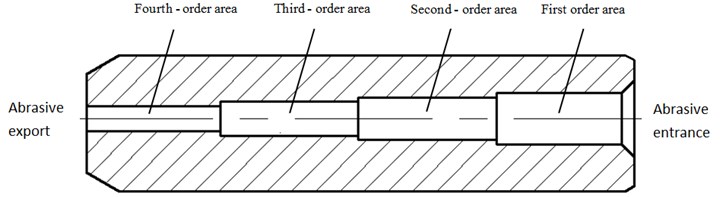
Variable diameter pipe parts in the food, pharmaceutical, automotive, military and other industrial production and daily life has a very wide range of applications, the use of high-pressure tubing, intake and exhaust manifolds, saxophone and other pipe instruments used in various vehicles such as pacemaker catheters, drug delivery pipes, automobiles, tanks and other devices on medical equipment has become an industrial production an indispensable part of manufacturing [1-3]. So variable diameter parts of the internal surface quality directly affect the performance of the entire system, practical applications require variable diameter pipe parts inside the surface smooth and no burrs, conventional processing methods are less difficult to achieve the desired surface accuracy, grinding grain flow polishing technology, successfully solved this problem [4-7]. In order to facilitate research and analysis, this paper only analyzes the fourth order variable aperture pipe, the order of the fourth order variable aperture tube is numbered, as shown in Fig. 1, the first, second, third and fourth order inner diameters are 1.2 mm, 1.0 mm, 0.8 mm, 0.6 mm, each order length is 3 mm.
Fig. 1Schematic diagram of the fourth order variable aperture tube
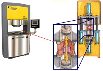
Grinding grain flow processing technology is based on particles for grinding tools, with fluid as carrier, through the flow of fluid in the surface of the components to promote the particles in the workpiece surface slip friction and collision, to achieve the purpose of removing the material. Abrasive flow polishing machine and its working principle schematic diagram shown in Fig. 2, the upper and lower hydraulic cylinder in the pressure to make the piston up and down to move, thereby promoting the abrasive in the workpiece surface relative movement, the workpiece surface produces a large shear force, in order to achieve the processing of surface materials, trace removal, to achieve the purpose of polishing [8-10].
Fig. 2Abrasive flow polishing machine and its working principle
2. Numerical simulation analysis of four -step variable-diameter pipe by grinding
In order to obtain better results, in this paper, FLUENT numerical simulation analysis, using a three-dimensional double solver, the boundary conditions use speed-inlet conditions and outflow conditions. The wall boundary is set to a non-slip boundary condition, assuming that the abrasive flow at the inlet is turbulent, the turbulence model is chosen as the -epsilon (2eqn) model. Liquid phase for the aviation hydraulic oil, the solid phase is silicon carbide, Set the silicon carbide volume fraction of 0.2, The initial processing temperature is 300 K.
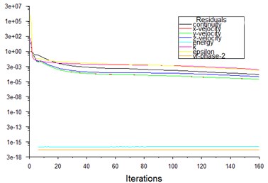
Respectively, the inlet speed of 30 m/s, 40 m/s, 50 m/s, 60 m/s numerical simulation analysis, after 160 iterations, to achieve convergence, the convergence curve is calculated as shown in Fig. 3.
Fig. 3Residual map of numerical simulation of fourth order variable diameter pipe
2.1. Analysis of dynamic pressure under different inlet speed
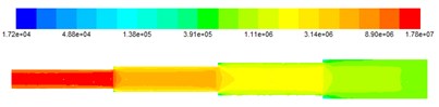
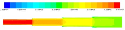
After the initial condition is set, the inlet speed of the workpiece during the grinding process of the dynamic pressure analysis, Fig. 4 shows the dynamic pressure cloud at different inlet velocities.
From the dynamic pressure diagram in Fig. 4, it can be seen that the abrasive flows from the first stage abrasive inlet at the beginning of the variable diameter pipe into the workpiece, after the grinding of the workpiece diameter of the workpiece, from the end of the diameter of the fourth-order abrasive exports out of the workpiece, the dynamic pressure is the smallest at the beginning of the abrasive inlet, with the increase in the order of dynamic pressure increases, there is no significant change in the pressure of each step, in the abrasive export dynamic pressure maximum, indicating that abrasive particles in the fourth step of the variable diameter tube movement, processing the best results.
Fig. 4Dynamic pressure plot at different inlet speeds
a) The inlet speed is 30 m/s
b) The inlet speed is 40 m/s

c) The inlet speed is 50 m/s

d) The inlet speed is 60 m/s
By observing the numerical simulation cloud, the numerical simulation of the grinding tube is carried out, due to changes in dynamic pressure in each order change distribution is more obvious, so the first-order region, second-order region, third-order region, fourth-order region is divided into four data areas for analysis, the analysis of the dynamic pressure of the abrasive grinding workpiece is analyzed, the numerical values of the dynamic pressure values listed in the four data areas are shown in Table 1.
Table 1Distribution table of dynamic pressure data under different inlet speed conditions
Entrance speed (m/s) | Dynamic pressure (×105MPa) | |||
First order area | Second-order area | Third-order area | Fourth-order area | |
30 | 3.91 | 11.1 | 31.4 | 89.0 |
40 | 6.87 | 19.5 | 55.5 | 158 |
50 | 10.1 | 29.3 | 84.5 | 244 |
60 | 15.6 | 44.1 | 125 | 355 |
Analysis of the data in Table 1, can see the dynamic pressure changes, (1) First analyze the same inlet speed under the conditions of dynamic pressure changes, from the table we can see the fourth-order region > third-order region > second-order region > first-order region, that is, with the abrasive into the workpiece, dynamic pressure gradually increased, the smaller the aperture, the better the polishing effect. (2) Second, the analysis of different inlet speed under the conditions of dynamic pressure changes, by analysis, increasing the velocity of the inlet increases the turbulence intensity of the abrasive flow, abrasive flow in the tube when the internal flow of the degree of disorder will become larger, so that the abrasive particles in the tube inside the irregular movement more intense, the impact of the wall on the pipe is even more intense, and the impact of the more violent impact after the degree of confusion will be more intense.
2.2. Analysis of turbulent kinetic energy under different inlet speed conditions
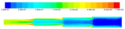
After the same initial condition is set, the turbulence kinetic energy analysis in the grinding process of the workpiece is carried out. As shown in Fig. 5, the turbulent kinetic energy cloud diagram under different inlet speed conditions is given.
From Fig. 5, the turbulence kinetic energy cloud diagram can be seen, the smaller the workpiece aperture, the greater the turbulence kinetic energy, while in the same aperture with the inflow of abrasive, turbulence kinetic energy has been reduced, this is because the abrasive grain flow process, with the abrasive on the wall of the cutting effect, abrasive energy reduction, from kinetic energy into grinding force and internal energy, thereby deburring the workpiece, rounded. And the turbulent kinetic energy is weakened from the wall of the workpiece to the center of the workpiece, showing a parabolic form. The greater the turbulence kinetic energy at the wall of the workpiece, the better the polishing effect on the workpiece.
By observing the numerical simulation cloud, the numerical simulation of the grinding tube is carried out, due to the abrasive near the wall before the workpiece polishing effect, so only to study near the wall at the turbulence kinetic energy, so the first-order region, the second-order region, the third-order region, the fourth-order area near the wall is divided into four data areas for analysis, The numerical analysis of the turbulent kinetic energy of the four data regions is shown in Table 1.
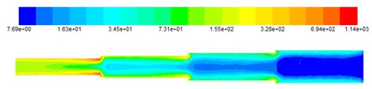
Fig. 5Turbulent kinetic energy cloud at different inlet velocities
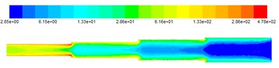
a) The inlet speed is 30 m/s
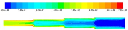
b) The inlet speed is 40 m/s
c) The inlet speed is 50 m/s
d) The inlet speed is 60 m/s
Table 2Turbine kinetic energy data distribution table under different inlet speed conditions
Entrance speed (m/s) | Turbulent kinetic energy (×10 m2/s2) | |||
First order area | Second-order area | Third-order area | Fourth-order area | |
30 | 0.615 | 1.33 | 2.86 | 13.3 |
40 | 1.07 | 2.29 | 4.90 | 22.5 |
50 | 1.63 | 3.45 | 7.31 | 32.8 |
60 | 2.29 | 4.82 | 10.1 | 44.8 |
As can be seen from Table 2, (1) For the same inlet speed, the turbulence kinetic energy distribution of four data regions, fourth-order region > third-order region > second-order region > first-order region, this is due to the smaller aperture, abrasive flow of the same circumstances, the greater the speed of abrasive, the greater the turbulence kinetic energy, the better the polishing effect on the wall of the workpiece. (2) With the increasing speed of the entrance, the turbulence kinetic energy of each data area is increasing, indicating that the increase in inlet speed will directly affect the turbulence kinetic energy changes, the greater the entrance, the better the polishing effect on the workpiece, but the speed cannot choose too much, excessive inlet speed may have damaging wear on the workpiece, so choose the appropriate entrance speed, can enhance the turbulent kinetic energy, thereby increasing the grinding effect.
3. Conclusions
Based on the numerical analysis of the four-step variable diameter pipe under the different inlet speed, the greater the entrance, the higher the accuracy of the inner surface of the workpiece. But the speed cannot choose too much, excessive inlet speed may have damaging wear on the workpiece, so choose the appropriate entrance speed, can enhance the turbulent kinetic energy, thereby increasing the grinding effect. Through the numerical analysis of dynamic pressure and turbulent kinetic energy, which provides a theoretical basis for the prediction of the actual polishing effect and the development of the polishing process.
References
-
Li Junye, Liu Weina, Yang Lifeng, et al. Numerical simulation of the behavior of grape flow in the micro-hole of injector. Coal Mine Machinery, Vol. 31, Issue 10, 2010, p. 56-58.
-
Ji Shiming, Zhang Ding Simulation and experiment of precision machining of soft grinding flow. Electrical and Mechanical Engineering, Vol. 29, Issue 3, 2012, p. 245-248.
-
Liang Fang, Jia Zhao, Bo Li, et al. Movement patterns of ellipsoidal particle in abrasive flow machining. Journal of Materials Processing Technology, Vol. 209, 2009, p. 6048-6056.
-
Fang L., Zhao J., Sun K., et al. Temperature as sensitive monitor for efficiency of work in abrasive flow machining. Wear, Vol. 266, Issue 7, 2009, p. 678-687.
-
Junye Li, Jinglei Hu, Xinming Zhang, et al. The research of polishing nozzle quality based on discrete element method. Journal of Measurements in Engineering, Vol. 5, Issue 1, 2017, p. 29-39.
-
Kenda J., Duhovnik J., Tavčar J., et al. Abrasive flow machining applied to plastic gear matrix polishing. International Journal of Advanced Manufacturing Technology, Vol. 71, Issue 71, 2014, p. 141-151.
-
Li Junye, Liu Weina, Yang Lifeng, et al. Study of abrasive flow machining parameter optimization based on taguchi method. Journal of Computational and Theoretical Nanoscience, Vol. 10, Issue 12, 2013, p. 2949-2954.
-
Junye Li, Jinglei Hu, Ningning Su, et al. Numerical analysis in viscosity-temperature characteristics of solid-liquid two-phase abrasive flow polishing. Journal of Measurements in Engineering, Vol. 5, Issue 3, 2017, p. 115-124.
-
Walia R. S., Shan H. S., Kumar P. Morphology and integrity of surfaces finished by centrifugal force assisted abrasive flow machining. International Journal of Advanced Manufacturing Technology, Vol. 39, Issue 11, 2008, p. 1171-1179.
-
Tzeng H. J., Yan B. H., Hsu R. T., et al. Self-modulating abrasive medium and its application to abrasive flow machining for finishing micro channel surfaces. International Journal of Advanced Manufacturing Technology, Vol. 32, Issue 11, 2007, p. 1163-1169.
About this article

The authors would like to thank the National Natural Science Foundation of China No. NSFC 51206011, Jilin Province Science and Technology Development Program of Jilin Province No. 20160101270JC and No. 20170204064GX, Project of Education Department of Jilin Province No. 2016386.
