Abstract
In order to investigate the acoustic behavior of composite material, in this paper, the acoustic target strength (TS) of rudders is obtained by combining the finite element method with the automatically matched layer technique. However, besides the composite material mentioned above, the considered materials of rudder models also include steel. In addition, the results of abeam direction and other angles are computed. Finally, the magnitude of abeam TS versus frequency shows that the acoustic scattering property of composite model is better than that of steel one when the frequency is higher than 1600 Hz. Moreover, the acoustic scattering properties are totally different when frequency is lower than 600 Hz for models with composite and steel materials. As for directivity patterns, the TS of composite model in each direction is lower than that of steel model at 3800 Hz, which matches the conclusions mentioned above.
1. Introduction
Acoustic scattering, as an interesting research field in recent decades, is extremely important in practical applications such as underwater acoustics and exploration engineering [1, 2]. Particularly, the acoustic target strength (TS) considering the echo characteristics of target objects is widely used not only to assess the biomass of fish stocks but also detect the activities of submarine [3-5]. Experientially, rudders are very important contributors for target strength of submarines so that it is obviously considerable to reduce the reflection from rudders. According to a number of studies, the composite materials exhibit many advantages of echo reduction [6-10].
During the past few decades, the theoretical and experimental investigations of composite materials have attracted more and more attention. For example, Nguyen [11] accomplished the experimental verification of the (0-3) composites mixed epoxy resin with tungsten particles. Additionally, Berryman [12] studied the inhomogeneous materials using the elastic-wave scattering theory. As research shows that composite materials provide some useful advantages such as absence of interactions and precise tuning of the frequency [13]. Therefore, considering the acoustic quality of composite materials is a project that could not be ignored.
In this paper, the finite element method is used to calculate the acoustic target strength of rudders. The steel and composite material properties of computation models are specially chosen to make a comparison for acoustic target strength characteristics.
2. Simulation method
As is known to all, the finite element method is frequently applied at for solving acoustic scattering problems, moreover, the automatically matched layer (AML) technique seems to be more efficient than the perfectly matched layer (PML) technique [14, 15]. Owing to the fact that elements of AML are automatically generated by the software solve, it provides a simple approach of specifying the PML region. Once the acoustic element is established, the AML property set on outermost layer of the acoustic element can simulate a non-reflecting boundary condition, namely, the acoustic infinite domains in FEM. Subsequently, the incident plane wave of unit amplitude entering from the far field is defined as a boundary condition. Furthermore, submerging the rudder in acoustic fluid leads to a force on the structure surface induced by the pressure field. Hence the surface mesh of the rudder should be coupled with the acoustic mesh and then a direct solver is applied to obtain the scattering field. In addition, in this paper, water is considered as the acoustic fluid mentioned above. The traditional TS is obtained with sound intensity level and acoustic intensity can be replaced by the ratio of acoustic pressure squared to characteristic impedance. Therefore, it is easy to acquire the TS by the following equation:
where denotes scattering sound pressure at the distance of 1 m to the acoustic center, is the incident sound pressure. Field points are accordingly inserted into the acoustic field and are used to calculate acoustic pressure in those places of interest.
3. Numerical procedure
It is convenient to deal with acoustic scattering problem by using LMS Virtual Lab 11-SL2. However, it is essential that the FEM model is obtained before the calculation. This paper establishes two kinds of simulation models, one is defined with steel material property and the other is composite material property.
Fig. 1The configuration of steel and composite rudder model
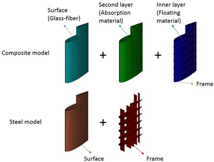
However, these models contain uniform outline and steel framework. As for the airfoil shape, the NACA 0021 is selected to describe the shape of the cross section. The longitudinal height is 3.5 m and the length of airfoil is 2.0 m. In addition, the outermost surface of composite model consists of glass-fiber material, the middle layer is made of absorption material, and the fillers replacing the cavities between the innermost framework and the middle absorption layer are floating material. Then the steel model consists of outer steel surface and inner steel framework. The details of structure models are shown in Fig. 1. The parameters of material properties used in this paper are listed in Table 1.
Table 1Mechanical properties of structural materials
Material | Young’s modulus | Shear modulus | Loss factor | Poisson’s ratio | Density |
Steel | 210 GPa | – | – | 0.3 | 7850 kg/m3 |
Glass-fiber | 23.5 GPa | 3.23 GPa | – | 0.13 | 1700 kg/m3 |
Sound absorption material | 140 MPa | – | 0.23 | 0.49 | 1100 kg/m3 |
Floating material | 120 MPa | – | – | 0.3 | 450 kg/m3 |
4. Results
In this section, abeam target strength and directivity patterns are both presented below. On the one hand abeam, TS describes the change of target strength with frequency, on the other hand directivity patterns exhibit the magnitude of each direction at several frequencies. It is worth mentioning that all of the results are computed at the plane of the cross section.
4.1. Abeam target strength
In particular, the abeam target strength is an extremely important indicator of the rudder structure so that the initial computations associated with plane wave scattering by rudders have concentrated on it.
Fig. 2The abeam target strength of steel and composite rudder model
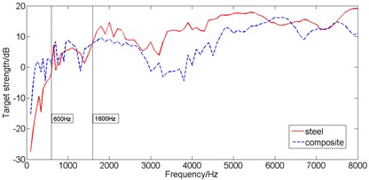
As shown in Fig. 2, the two rudder models obviously show different performance at different frequency. The TS of steel model is lower than that of the composite model when the frequency is less than 600 Hz, and composite materials perform even worse for acoustic properties. From 600 Hz to 1600 Hz, there is little difference between the two models about TS magnitude and both of the two models show similar behaviors. When the frequency is higher than 1600 Hz, the composite model makes a good effect of reducing TS magnitude compared with steel model.
4.2. Directivity patterns of TS
According to the results of abeam TS, it is obvious that there are different behaviors of abeam TS changing with frequency. However, due to the results of single direction describing no information about other directions, the target strength of other angles on the plane of cross section should be further considered. The final results are shown by the directivity patterns as follows.
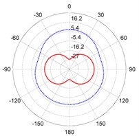
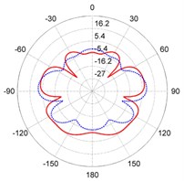
Fig. 3The directivity patterns of target strength for the steel and composite rudder models at different frequencies: a) f= 300 Hz, b) f= 1000 Hz, c) f= 3800 Hz, d) f= 6700 Hz
a)
b)
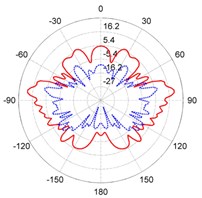
c)
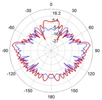
d)
As shown in the panels of Fig. 3, the directivity patterns show perfect symmetries because the models are symmetric about the middle longitudinal section. As the frequency increases, furthermore, the numbers of lobes increase accordingly. Near the abeam direction, the value of TS is larger than values in any other direction at same frequency for the two models. At 300 Hz, the TS of the steel model has a smaller value in all directions. On the contrary, the TS of the composite model exhibits smaller values at 3800 Hz and 6700 Hz in most directions. At high frequencies, acoustic scattering properties are improved by using composite materials.
5. Conclusions
To our knowledge, TS indicates the reflection ability of objects which is related to the structure and material of objects. In this paper, the effects of steel and composite materials are compared for acoustic scattering property with simulation computations. Using the combination of FEM with AML technique, TS is easily obtained. In summary, acoustic scattering behaviors of composite are better than steel model at a relatively higher frequency which matches other relevant studies. At 6700 Hz, the effects of reducing TS become unapparent, which should be further studied later.
References
-
Chai Y. B., Li W., Li T. Y., Gong Z. X., You X. Y. Analysis of underwater acoustic scattering problems using stable node-based smoothed finite element method. Engineering Analysis with Boundary Elements, Vol. 72, Issue 1, 2016, p. 27-41.
-
Chai Y. B., Gong Z. X., Li W., Li T. Y., Zhang Q. F., Zou Z. H., Sun Y. B. Application of smoothed finite element method to two-dimensional exterior problems of acoustic radiation. International Journal of Computational Methods, 2018, https://doi.org/10.1142/S0219876218500299.
-
Zhang J., Chen P. M., Chen G. B., Fang L. C., Tang Y. Acoustic target strength measurement of banded grouper (Epinephelus awoara (Temming and Schlegel, 1842)) and threadsial filefish (Stephanolepis cirrhifer (Temming and Schlegel, 1850)) in the South China Sea. Journal of Applied Ichthyology, Vol. 29, Issue 6, 2013, p. 1453-1455.
-
Kloser R. J., Williams A., Koslow J. A. Problems with acoustic target strength measurements of a deepwater fish, orange roughy (Hoplostethus atlanticus, Collett). ICES Journal of Marine Science, Vol. 54, Issue 1, 1997, p. 60-71.
-
Schneider H. G., Berg R., Gilroy L., Karasalo I., Macgillivray I., Morshuizen M. T., Volker A. Acoustic scattering by a submarine: results from a benchmark target strength simulation workshop. Proceedings of the Tenth International Congress on Sound and Vibration, 2003, p. 2475-2482.
-
Cavalieri A. V. G., Donadon M. V., Wolf W. R. Acoustic scattering by finite composite plates. 21st AIAA/CEAS Aeroacoustics Conference, 2015.
-
Cavalieri A. V. G., Wolf W. R., Jaworski J. W. Acoustic scattering by finite poroelastic plates. 20th AIAA/CEAS Aeroacoustics Conference, 2014.
-
Zhao H., Tan H. B., An J. Y., Xu H. T. Sound characteristics of viscoelastic coating containing periodic cavities by the finite element method. Chinese Journal of Acoustics, Vol. 23, Issue 1, 2004, p. 36-44.
-
Mouring Sarah E. Composites for naval surface ships. Marine Technology Society Journal, Vol. 32, Issue 2, 1998, p. 41-46.
-
Saeedifar M., Ahmadi Najafabadi M., Yousefi J., Mohammadi R., Hosseini Toudeshky H., Minak G. Delamination analysis in composite laminates by means of acoustic emission and bi-linear/tri-linear cohesive zone modeling. Composite Structure, Vol. 161, 2017, p. 505-512.
-
Nguyen T. N., Lethiecq M., Levassort F., Pourcelot L. Experimental verification of the theory elastic properties using scattering approximations in (0-3) connectivity. Composite Materials, Vol. 43, Issue 4, 1996, p. 640-645.
-
Berryman J. G. Theory of elastic properties of composite materials. Applied Physics Letters, Vol. 35, Issue 11, 1979, p. 856-858.
-
Kafesaki M., Economou E. N. Multiple-scattering theory for three-dimensional periodic acoustic composites. Physical Review B, Vol. 60, Issue 17, 1999, p. 11993-20001.
-
Singer I., Turkel E. A perfectly matched layer for the Helmholtz equation in a semi-infinite strip. Journal of Computational Physics, Vol. 201, Issue 2, 2004, p. 439-465.
-
Kaltenbacher B., Kaltehbacher M., Sim I. A modified and stable version of a perfectly matched layer technique for the 3-D second order wave equation in time domain with an application to aeroacoustics. Journal of Computational Physics, Vol. 235, 2013, p. 407-422.
About this article

