Abstract
In this paper, unlike the existing studies, vibro-acoustic modeling and analysis of a rectangular acoustic cavity bounded by a flexible panel is conducted by three modeling techniques in a broad frequency range (up to 6.4 kHz). The finite element method (FEM) and statistical energy analysis (SEA) are employed at the low and high frequency range respectively. For the mid-frequency range, a hybrid FE-SEA method is employed to deal with the drawbacks in application of single deterministic or statistical methods. In this case, studies of the interior sound pressure and panel vibration responses for the structure-acoustic coupled system are made under external normal concentrated force acting at the flexible plate. And then comparisons are used to validate the three models and verify their accuracy through experimental investigations. Deviations between the numerical and test results are also discussed.
1. Introduction
The interaction between a sound field in an enclosure and its flexible boundary is a critical problem, and a good understanding of it is particularly important to the control of sound field in an enclosure. Moreover, vibro-acoustic modeling of an enclosure is quiet importance in the design and analysis of an active noise control system. An approach to this modeling proposed by Montazeri, A. et al. [1, 2] is to consider an enclosure with rigid boundary conditions and the works of Al-Bassyiouni, M. [3] and Fang, B. [4] extend to the case where the enclosure with a flexible boundary is considered. Excitation of the flexible plate by external force or sound source will cause vibrations on the plate and induces noise inside the cavity. Due to the coupling between structural vibrations and acoustical field, these systems are termed vibro-acoustic systems. In early works of Dowell [5, 6], the modeling of vibrations of panel backed by an enclosure is studied considering the interaction between structural vibration and acoustical field. Pan and Bies [7] have studied the effect of structural-acoustic coupling on the sound field in an enclosure with flexible wall simply supported based on the classical modal coupling method. Asymptotic modal analysis technique is proposed by Peretti et al. [8] to analyze such problems. And it is shown that it has the advantage of solving dynamic problems with a large number of modes compared with traditional methods. A mechanics-based analytical model is developed to address the interactions of the coupling panel and sound field inside a rectangular enclosure by Balachandran, B. et al. [9]. In modeling the effect of coupling between the flexible plate and the enclosure, both simply supported and clamped boundaries have been used, but several studies [4, 10, 11] used only simply supported because the analytical derivation of the model for the coupled system is less complex.
Computational techniques have been employed to solve the vibro-acoustic problems thanks to the rapid advancement of computing power. Finite element method (FEM) [12, 13] and boundary element method (BEM) [14, 15] are two examples of computational techniques, which can be used to study the characteristics of sound radiation from a box-type structure by identifying the structural modes of the surfaces and acoustical modes of the interior space. At low frequencies, where acoustic and structural wavelengths are long compared to the dimensions of the sidewall structure and interior cavity, the vibro-acoustic response is deterministic and can be adequately described by a deterministic approach such as finite element analysis. However, at higher frequencies and associated shorter wavelengths, the required size of the finite elements becomes so small that the deterministic approach becomes impractical. This is not only due to a growth in the model size, but also because it is exceedingly difficult to model important variations in the structure that become significant at high frequencies, such as material property variations, dimensional variations, and random variations due to manufacturing. In light of such practical limitations, a statistical description named statistic energy analysis (SEA) [16, 17] becomes an essential tool to draw meaningful conclusions about high-frequency responses. However, this method cannot get results at individual locations and single frequencies instead only provide space and frequency averages.
There is also a middle frequency range where a mixed behaviors exist. Often, in this band, some subsystems present a deterministic behavior, while some other subsystems require a statistical description due to a high modal density. As above, it is impossible to predict the responses of complex structure over a broad band of frequencies using a single method. Recently, Shorter et al. [18-22] have proposed a hybrid FE-SEA modeling technique to study the so-called mid-frequency problem, in which the deterministic parts are modeled by FEM, while the other components are modeled by SEA. On the one hand, each statistical subsystem is modeled by a single energy variable which leads to a large reduction in the size of computational model required. On the other hand, this method obtains results at space and frequency averages of the target quantities without the need for Monte Carlo simulations. The panel-cavity coupling structure of a wall surface and an acoustic space is a well representation of many engineering applications, for example, the cabins of car, ship and airplane. Hence, it is of critical importance to study the interactions between the structure vibration and interior sound pressure response before the launch of new productions.
However, due to the vibro-acoustic properties of the excitations, taking the vehicles for example, its dynamic response extends to over a broad range of frequencies where there is not a single methodology able to account for. Motivated by above, an investigation on the vibro-acoustic responses of a coupled panel cavity system in a broad frequency range is presented. The system is driven by an external axial force at the flexible plate. In this paper, a rectangular acoustic cavity bounded by a flexible panel is examined. The vibro-acoustic response of this panel-cavity coupled system is further considered using three models in a broad frequency domain (up to 6.4k Hz). The procedures and coupled vibro-acoustic modeling techniques adopted to obtain the structure vibration and inner acoustic response of the given system are presented. The purpose of the present contribution is to check the modeling techniques feasibility for fluid-structural problems in a broad frequency domain and finally verify its accuracy through an experimental verification.
2. Theoretical formulations
2.1. Vibro-acoustic problems description
Fig. 1(a) shows an elastically restrained plate as one of the surfaces enclosing a rectangular acoustical cavity. The cavity is of dimensions 1.135 m×0.880 m×0.715 m. The floor of cavity is taken at 0 with one wall at being flexible plate. The five rigid panels are made of isotropic plywood with Young’s modulus 6 GPa, Poison’s ration 0.25, mass density 700 kg/m3 and wall thickness 0.017 m. While the flexible panel is made of steel with elastic properties: Young’s modulus 200 GPa, Poisson’s ration 0.3125, mass density 7800 kg/m3 and wall thickness 0.001 m. The acoustic domain consists of an acoustic cavity filled with air at room temperature with elastic properties: mass density 1.225 kg/m3, sound speed 340 m/s.
Fig. 1Plate-cavity structure
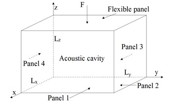
a) a rectangular acoustic cavity bounded by a flexible panel
b) reduced vibro-acoustic model
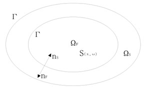
Now, the linear vibration of a damped structure subjected to external loads, coupled with its interior acoustic cavity is considered. The vibro-acoustic model, shown in Fig. 1(b), is developed in the context of the three dimensional linear elasto-acoustics for a coupled system which constitutes a damped elastic structure and a closed cavity filled with fluid. We denote the generic point of referred to a Cartesian reference system as .
The structure of is the bounded domain with a sufficiently smooth boundary and is the outward unit normal to denoted as . We denote the displacement field in as . The internal acoustic cavity occupies a bounded domain of filled with a dissipative acoustic fluid. The boundary is . Let is the outward unit normal to and we have on . The pressure field in is denoted as .
The equation governing the dynamics of the structure in is writen as [23]:
where is the stress tensor, is the mass density, represents the body force field, represents the displacement field of the structure. is the fluid pressure field at the coupling interface and is the surface force field.
For interior acoustic fluid, the equation in terms of pressure can be written as [24, 25]:
in which represents the speed of air, represents the mass density of the fluid, is the coefficient due to the viscosity of the fluid, represents the source term.
2.2. FEM modeling at low frequencies
At low frequencies, the FEM is one of the most appropriate numerical techniques to solve above vibro-acoustic problems. Here, the FE discretization of the displacement field of the structural part is denoted as and corresponding to the pressure field of the fluid is denoted as . Therefore, the FE matrix equation can be defined by Eqs. (1-4) in terms of and :
in which is a symmetric complex matrix corresponding to the dynaimcal stiffness matrix of the structure. is a symmetric complex matrix corresponding to the dynamical stiffness matrix of the acoustic fluid. And:
here, ,, is the mass matrix, damping matrix and stiffness matrix of the structure. , , is the mass matrix, damping matrix and stiffness matrix of the acoustic cavity, respectively.
2.3. SEA modeling at high frequencies
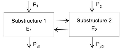
In SEA modeling technique, the model is divided into many substructures which are described by space and frequency average energy response levels. It is worth noting that energy dissipation is assuming proportional to the vibration energy in a substructure. Therefore, the SEA equation expressing the energy balance of substructures is described as follows, and a simple two-substructure SEA model is shown in Fig. 2:
in which represents the external power input, represents angular frequency at the band center, and is the lumped total energies of a substructure. represents the loss factor matrix. And, here, is the internal loss factor which is dependent on the frequency, and represents the coupling loss factor from the substructure to .
Fig. 2A simple two-substructure SEA model
In general, and can be acquired by hammering test. And they are described by:
in which represents the th substructural energy from the substructure . is the energy of the substructure which can be acquired by the hammer test.
And:
where, , respectively represents the external excitation force and the acceleration spectrum at a generic point. And represents the mass of substructure .
Therefore, at this frequency band, the frequency responses and vibration energy levels of the substructures can be acquired by solving the power balance Eq. (8).
2.4. Hybrid FEM-SEA modeling at middle frequencies
A key feature of the hybrid method is to divide the system into FE substructures and SEA substructures. The heart of hybrid modeling technique is the concept of a “diffuse field reciprocity principle” [22] as shown in Fig. 3, which is consist of one FE substructure and two SEA substructures.
Fig. 3Schematic diagram of a hybrid FE-SEA model
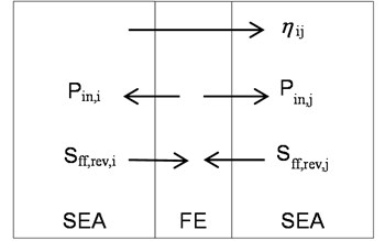
In Fig. 3 is the cross-spectral matrix of force written as:
in which is the modal density. represents the dynamic stiffness matrix of the SEA substructure expressed on the FE degrees of freedom which is given in cross-spectral form by:
where represents the cross-spectral matrix of the external forces . is the dynamic stiffness matrix corresponding to the FE model.
By solving the power balance Eq. (17), in order to solve Eq. (15), we can obtain the average energy response of the SEA substructures:
in which:
where , is the damping loss factor and the coupling loss factors, respectively.
Therefore, the response of the FE substructures can be calculated by Eq. (15) once the SEA substructures’ energy levels are found through Eq. (17).
2.5. Frequency band division for the models
In this section, the boundary between the three analyses is divided based on the modal densities (number of modes per band) studied by Shorter [26]. For ideal subsystems, such as bars, beams, flat plates, thin walled cylinders and acoustic volumes, the modal densities of which can be given by the analytical Eq. (20) and Eq. (21):
where is number of modes per band, is the bandwidth of the frequency.
Fig. 4Number of modes per 1/3rd octave band for subsystems
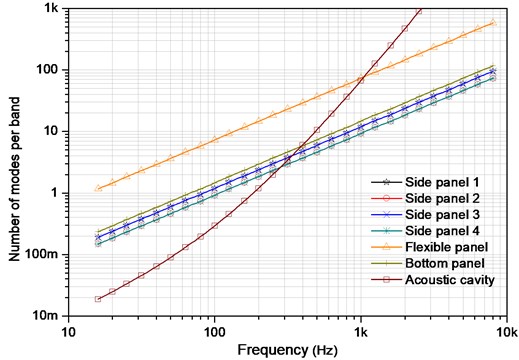
Taking the influence of the surface area and total length of edges of the acoustic field on the modal density into account, the modal density of three-dimensional acoustic cavity can be expressed as:
where is the sound speed, is the volume of the acoustic field, is the surface area of the acoustic cavity and is the total length of the edges.
Number of modes in 1/3rd octave band for the subsystems is plotted in Fig. 4. It is shown that the acceptable confidence interval of the SEA model is satisfied starting from 500 Hz, where the reliable structural-acoustic predictions have more than 5 modes in the bandwidth and the modal overlap factor starts to be accurate. In other words, the SEA effective working frequency range is beyond 500 Hz (namely 5). Above 100 Hz, as can be observed, most of the substructures have at least one mode in band which develops a usable SEA subsystem. Consideration of the premise that each SEA subsystem should have at least one mode in the lowest band, therefore, a theoretical low frequency limit for the hybrid FEM-SEA analysis is set around 100 Hz. Thus, for the given system, the mid-frequency range is defined above 100 Hz to 500 Hz, in which the hybrid FE-SEA method is applicable (namely 15). Below the 100 Hz, the full FE model can guarantee the prediction accuracy and less time consuming.
3. Experimental investigations and discussion
3.1. Experiment scheme
In this paper, two different studies are made of the coupled rectangular enclosure panel-cavity system in order to demonstrate the validity of the given three models, plotted in Fig. 5, in the semi-anechoic room.
The system is excited by a harmonic force locates at () on the flexible panel, over the frequencies up to 6.4 kHz. In this work, the panels’ vibration response and interior sound pressure response of the given panel-cavity coupled system are studied. It is shown in Fig. 4 that side panels vibration and noise levels inside the cavity are measured using several acceleration sensors and microphone for sake of a verification. The FE model and hybrid model are used to compute structure vibration responses below 500 Hz with a 1 Hz bandwidth and over the range 500 Hz-6.4 kHz in one-third octave band for SEA model. On the other hand, the interior acoustic responses are only predicted over the full frequency range in one-third octave band. The interior noise signal is recorded using data acquisition front end and the noise signal is processed by A-weighted network.
Fig. 5Diagrammatic sketch of the experimental setup
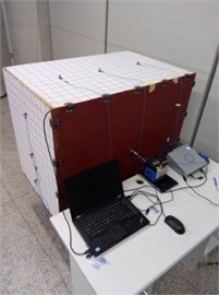
a) Acceleration sensors location
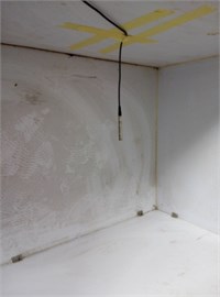
b) Microphone location
3.2. Panel vibration response
Here, the vibration response of point () on the side panel 1 is considered. Comparisons between the simulated result and the measured value are plotted in Fig. 6. As shown in the graph, on the whole, the numerical results almost agree with the tests as to the frequency of the various peaks in the responses at low and middle frequencies (below 400 Hz) and the trend across the high-frequency domain (500-6.4 kHz). However, the numerical result tends to be consistently overestimated at lower frequency (100-200Hz) and be deviated at higher frequency (400-500 Hz) of the hybrid model. This is possibly due to low modal density at lower frequencies, and the effect of stiffeners and lumped masses which are not modeled in hybrid model. In addition, another reason may be traced to the fact that the acoustic field is not diffuse at low frequencies. In other hand, the deviation of hybrid model (400-500 Hz) may be caused by uncertainties which increase with an increase in frequency.
Fig. 6Vibration response comparisons between the simulated and the test
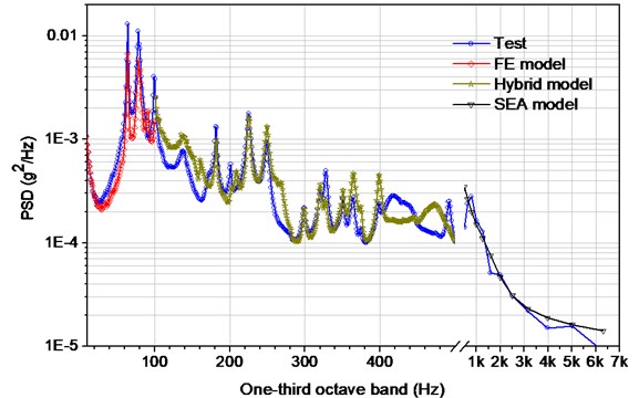
Fig. 7Interior acoustic response comparisons between the simulated and tests
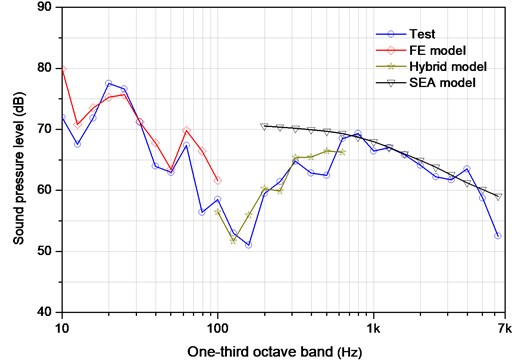
3.3. Interior acoustic response
As plotted in Fig. 7, the sound pressure data obtained from the microphone () in the cavity is compared with the simulation. It is observed that the results generally match within several dBs of tests for the given frequency range. However, some discrepancies (e.g. 400-600 Hz) are also observed which is likely due to the underlying assumptions for SEA, specifically that each structural component is sufficiently random and that the coupling between subsystems is sufficiently weak. On the other hand, the actual panel-cavity coupled system has tiny gap and holes due to the presence of flexible panel, whereas the model has assumption of hard-walled boundary conditions. Another possible reason could be the inaccurate acoustic modal damping values used in the model. namely, it can lead to the prediction of a stronger response if the damping is too low.
4. Conclusions
Modeling and analysis of vibro-acoustic response for a rectangular cavity bounded by a flexible panel is addressed in this work. Three models are described to predict structural vibration and interior noise level of a coupled panel-cavity system in a broad frequency domain: an FEM model for low frequencies (below 100 Hz), a hybrid model for medium frequencies (100-500 Hz) and an SEA model for high frequencies (500-6.4 kHz). And then two studies of panels’ vibration response and interior acoustic response are made based on the three models.
From the comparison between numerical and test results can be stated that in general each numerical model in its application frequencies is working correctly as well as a good continuity. Furthermore, it is worth noting that the accuracy of prediction depends strongly on the frequencies each method works in, which are determined by modal densities of substructures.
The modeling techniques present in this paper can be applied to studies on the prediction of the vibration and noise of the complex structures with uncertainties at an early design stage. And this procedure for vibro-acoustic analysis can be further extended to structures comprising a number of substructures in wide frequency range without inaccuracy and time-consuming computation. A prime example of this situation arises in the automotive industry, where the conventional finite element models having several million degrees of freedom are often employed to represent a whole vehicle, while at the same time it is well known that the vibro-acoustic performance of vehicles is very sensitive to the uncertainties with an increase of the frequency. In addition, this study provides new and interesting insights into the reduction of the vibration and noise of the class of built-up box-type structures such as the cab of automobiles and engineering machineries, which are presently being pursued by the authors.
References
-
Montazeri A., Poshtan J., Kahaei M. H. Modal analysis for global control of broadband noise in a rectangular enclosure. Noise Notes, Vol. 6, Issue 4, 2007, p. 41-56.
-
Montazeri A., Poshtan J., Kahaei M. H. Analysis of the global reduction of broadband noise in a telephone kiosk using a MIMO modal ANC system. International Journal of Engineering Science, Vol. 45, Issue 2, 2007, p. 679-697.
-
Al-Bassyiouni M., Balachandran B. Sound transmission through a flexible panel into an enclosure: structural-acoustics model. Journal of Sound and Vibration, Vol. 284, Issue 1, 2005, p. 467-486.
-
Fang B., Kelkar A. G., Joshi S. M., et al. Modeling, system identification, and control of acoustic-structure dynamics in 3-D enclosures. Control Engineering Practice, Vol. 12, Issue 8, 2004, p. 989-1004.
-
Dowell E. H., Voss H. M. The Effect of a Cavity on Panel Vibration. AIAA Journal, Vol. 1, Issue 2, 1963, p. 476-477.
-
Dowell E. H., Gorman G. F., Smith D. A. Acoustoelasticity: general theory, acoustic natural modes and forced response to sinusoidal excitation, including comparisons with experiment. Journal of Sound and Vibration, Vol. 52, Issue 4, 1977, p. 519-542.
-
Pan J., Bies D. A. The effect of fluid–structural coupling on sound waves in an enclosure-theoretical part. Journal of the Acoustical Society of America, Vol. 87, Issue 2, 1990, p. 691-707.
-
Peretti L. F., Dowell E. H. Asymptotic modal analysis of a rectangular acoustic cavity excited by wall vibration. AIAA Journal, Vol. 30, Issue 5, 1992, p. 1191-1198.
-
Balachandran B., Sampath A., Park J. Active control of interior noise in a three-dimensional enclosure. Smart Materials and Structures, Vol. 5, Issue 1, 1996, p. 848-853.
-
Lin T. R., Pan J. Sound radiation characteristics of a box-type structure. Journal of Sound and Vibration, Vol. 325, Issue 4, 2009, p. 835-851.
-
Howard C. Q., Hansen C. H., Zander A. Vibro-acoustic noise control treatments for payload bays of launch vehicles: discrete to fuzzy solutions. Applied Acoustics, Vol. 66, Issue 11, 2005, p. 1235-1261.
-
Craggs A. An acoustic finite element approach for studying boundary flexibility and sound transmission between irregular enclosures. Journal of Sound and Vibration, Vol. 30, Issue 3, 1973, p. 343-357.
-
Petyt M. Introduction to Finite Element Vibration Analysis. Cambridge University Press, 2010.
-
Sauter S. A., Schwab C. Boundary Element Methods. Springer, Berlin, Heidelberg, 2011.
-
Banerjee P. K., Butterfield R. Boundary Element Methods in Engineering Science. McGraw-Hill, London, 1981.
-
Burroughs C. B., Fischer R. W., Kern F. R. An introduction to statistical energy analysis. The Journal of the Acoustical Society of America, Vol. 101, Issue 4, 1997, p. 1779-1789.
-
Lyon R. H. Theory and Application of Statistical Energy Analysis. Elsevier, 2014.
-
Shorter P. J., Langley R. S. Vibro-acoustic analysis of complex systems. Journal of Sound and Vibration, Vol. 288, Issue 3, 2005, p. 669-699.
-
Cotoni V., Shorter P., Langley R. Numerical and experimental validation of a hybrid finite element-statistical energy analysis method. The Journal of the Acoustical Society of America, Vol. 122, Issue 1, 2007, p. 259-270.
-
Langley R. S., Cotoni V. Response variance prediction for uncertain vibro-acoustic systems using a hybrid deterministic-statistical method. The Journal of the Acoustical Society of America, Vol. 122, Issue 6, 2007, p. 3445-3463.
-
Shorter P. J., Langley R. S. On the reciprocity relationship between direct field radiation and diffuse reverberant loading. The Journal of the Acoustical Society of America, Vol. 117, Issue 1, 2005, p. 85-95.
-
Langley R. S. On the diffuse field reciprocity relationship and vibrational energy variance in a random subsystem at high frequencies. The Journal of the Acoustical Society of America, Vol. 121, Issue 2, 2007, p. 913-921.
-
Marsden J. E., Hughes T. J. R. Mathematical Foundations of Elasticity. Courier Corporation, 1994.
-
Lighthill J. Waves in Fluids. Cambridge University Press, 2001.
-
Munson B. R., Young D. F., Okiishi T. H. Fundamentals of Fluid Mechanics. New York, 1990.
-
Shorter P. Recent Advances in Automotive Interior Noise Prediction. SAE Technical Paper, 2008.
Cited by
About this article

This work is funded by Science and Technology Support Planning of Jiangsu province (Grant No. BE2014133), The Open Foundation of Key Laboratory of Underwater Acoustic Signal Processing (Grant No. UASP1301) and Prospective Joint Research Project of Jiangsu province (Grant No. BY2014127-01).
