Abstract
This paper focuses on the improved design of Tc bearing’s structure form. A sand transmission groove is designed around the outer ring of Tc bearing to make it easy to remove solid particles, and the dynamic pressure Reynolds equation of Tc bearing is solved and the static characteristics of two structures of Tc bearing are compared and analyzed. Overall, conclusions are drawn: the carrying capacity of Tc bearing with the sand transmission groove is less than that of the original Tc bearing; the end discharging capacity of Tc bearing with the sand transmission groove is more than that of the original Tc bearing, which is in favor of the removal of solid particles from the Tc bearing and the enhancement of sand removal function; improving the dynamic characteristics of the liquid film of Tc bearing, Tc bearing with the sand transmission groove is suitable for the rotor system with high-speed light-load of MWD.
1. Introduction
Tc bearing is a sliding bearing for down-hole hostile environment, which has been successfully applied in positive displacement motor and turbodrill, In some down-hole tools with rotary dynamic seal modes, such as high-speed light-load rotor system composed of continuous wave pulse generator, etc. for measurement while drilling, magnetic coupling is combined with Tc bearing to replace traditional dynamic seal in order to overcome the disadvantage of extremely short service life of the rubber parts among dynamic seal components in the hostile environment. However, the bit teeth contacting with the strata intermittently, etc. cause very serious vibration and impact, stability of the rotor system with Tc bearing is higher. In the paper, fluid dynamic pressure lubrication theory is regarded as the foundation for analyzing Tc bearing working principle, thereby improving its surface structure, enhancing its sand removal function and heightening stability of the rotor system.
2. Fluid dynamic pressure model of Tc bearing at steady state
Currently, the structure of the integral radial Tc bearing for down-hole tools is shown in Fig. 1 [1].
Fig. 1Profile map of integral radial Tc bearing
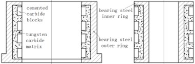
It is composed of inner and outer rings, wherein the inner ring is fixed on the axle, which is rotated with the axle together. The outer ring is connected with the drill collar. Since Tc bearing is immersed in the drilling fluid with flow velocity up to 20-30 m/s and containing solid particles with granularity up to 74 micron. High hardness carboloy metal blocks and tungsten carbide powder is sintered on a steel body in order to resist erosion of drilling fluid and wearing of particles [2], thereby forming a hard contact surface for longer service life.
2.1. Dynamic pressure equation of Tc bearing at steady state
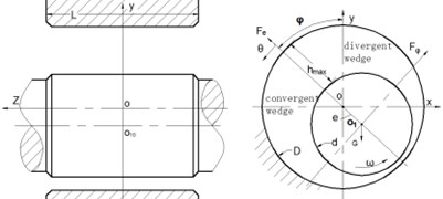
Fig. 2 shows the coordinate system of Tc bearing dynamic pressure equation, axis is along the width direction of the bearing, its origin o is located on the midpoint of bearing outer ring width ; coordinate can be established through the cross section of bearing outer ring center ; the eccentric distance between bearing outer ring center o and axle journal (bearing inner ring and axle matched section are known collectively as axle journal) center is expressed with ; is the angle with ligature during maximum liquid film thickness as starting edge for rotating along the direction of axle rotation. is the included angle between ligature and external load . It is set that the axle journal is rotated counterclockwise at angular velocity . Tc bearing static property refers to the performance of the bearing liquid film when the bearing is operated at static balance position.
Fig. 2Coordinate system of Tc bearing dynamic pressure equation
Reynolds equation about liquid film dynamic pressure is the foundation of fluid dynamic pressure sliding bearing. The general form is shown as follows [3-6]:
In the Eq. (1), is velocity of moving surface along direction, m/s; refers to liquid film pressure intensity, N/m2; refers to lubricant viscosity, pa.s; refers to liquid film thickness, wherein, m; refers to bearing gap,, and are axle and bearing diameters, m; refers to eccentricity ratio,.
2.2. Tc bearing of sand transmission groove type and steady state dynamic pressure equation thereof
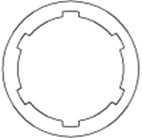
The liquid film pressure in the Tc bearing convergent wedge is larger than the pressure of bearing external environment. Therefore, a part of drilling fluid is squeezed from two ends of the bearing. While the liquid film in the divergent wedge is lower than the pressure of the external environment, a part of external drilling fluid can be pressed into the divergent wedge. After the solid particle enters into the bearing through the divergent wedge negative pressure zone, since the viscidity can rotate and enter into the convergent wedge with the inner ring rotary, it can be moved from the part with the maximum liquid film thickness to the part with the minimum thickness. If it is not flushed by the fluid squeezed from two ends of the bearing due to the high pressure in the convergent wedge, when solid particle passes through the part with the minimum liquid film thickness, and the load is higher than the designed limit, solid particle cannot pass through the gap between the inner ring and the outer ring, bearing inner ring is pushed out of the outer ring by solid particles as a result, the eccentricity ratio is reduced, the bearing carrying capacity is reduced, thereby resulting in bit bouncing accident. The surface structure of existing Tc bearing outer ring is improved in order to increase the change of discharging solid particles from bearings, a sand transmission groove is designed, Fig. 3 shows the end map of the Tc bearing outer ring after improvement designed. The originally flat hard alloy blocks in Fig. 1 are slightly protruded from the base body, which are neatly arranged along the axial direction. When particles fall into the liquid film, it can be pushed into the nearest groove along the fluid flow rotation direction, thereby increasing the possibility of being flushed by high pressure liquid and reducing bit bouncing accidents caused by particles.
Fig. 3Tc bearing with sand transmission groove on the outer ring
Reynolds dynamic pressure equation of Tc bearing primary structure is also applicable to the sand transmission groove structure, the liquid film thickness of the part with a groove expression is shown as follows (In the formula, is groove depth):
3. Comparison of static properties of two structural style bearings
The groove depth of six sand transmission grooves are adopted as an example for analyzing and comparing the static characteristics of Tc bearings in two structures when the eccentricity ratio is not larger than 0.6.
3.1. Dimensionless liquid film pressure of liquid film
The distribution of liquid film dynamic pressure in two bearing convergent wedges is obtained through calculation. The pressure distribution of primary structure Tc bearing convergent wedge liquid film is shown in the left part of Fig. 4. The dynamic pressure of the sand transmission groove bearing convergent wedge liquid film is shown in the right part of Fig. 4.
Fig. 4Three-dimensional diagram of liquid film dynamic pressure
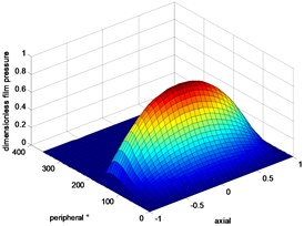
a)
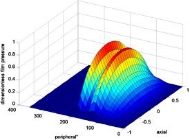
b)
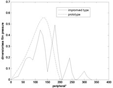
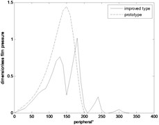
The pressure distribution shapes thereof are different. The dynamic pressure of the sand transmission groove Tc bearing liquid film is smaller than that of primary structure because the liquid film is not continuous due to the sand transmission groove of the sand transmission groove Tc bearing outer ring, and the pressure value is reduced. Fig. 5 shows the distribution comparison diagram of dynamic pressure in liquid film circumference of Tc bearings in two structures. The two figures are compared (left 0.4 and right 0.6), and the follows can be obtained: the maximum pressure value difference thereof is also increased with the increase of the eccentricity ratio. The originally integral convergent wedge is divided into several wedges by grooving. Meanwhile, the circumferential pressure distribution scope is also increased. It has the characteristics of multi-lobe bearing and multi-wedge bearing liquid films, and the dynamic property of the liquid film is improved.
Fig. 5Peripheral direction pressure profile of liquid film dynamic pressure
a)
b)
3.2. Dimensionless carrying capacity of liquid film
The calculation of unit width dimensionless carrying capacity under Reynolds condition [5] is shown as follows:
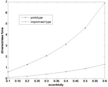
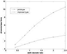
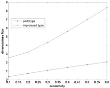
The carrying capacity change conditions of Tc bearings in two structures with eccentricity ratio and width diameter ratio in Fig. 6 are compared, and the follows are obtained: 1) The carrying capacity of the two structures are increased with the increase of eccentricity ratio and width diameter ratio; 2) When the width diameter ratio is not changed, and the eccentricity ratio is changed, sand transmission groove carrying capacity is only one fifth of the primary structure carrying capacity; 3) When the eccentricity ratio is not changed, and the width diameter ratio is changed, the sand transmission groove carrying capacity is only one third of the primary structure carrying capacity.
Fig. 6Comparison diagram of liquid film bearing capacity
a)
b)
3.3. Dimensionless discharging capacity discharged from bearing end
Tc bearing structure belongs to a radial bearing without an oil duct. The rectangular integral formula adopted in the both-end discharge flow is dimensionless flow rate computational formula [5] as follows:
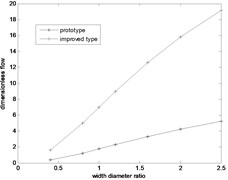
The follows are obtained through analyzing Fig. 7: 1) The end discharging capacity of two structures is prominently increased with the increase of eccentricity ratio and width diameter ratio; 2) The sand transmission groove discharging capacity is three to four times of primary structure end discharging capacity.
Fig. 7Discharging capacity comparison diagram
a)
b)
4. Conclusions
Compared with primary structure Tc bearing, the sand transmission belt type has the following features: 1) The originally integral convergent wedge is divided into several parts by grooving. Meanwhile, the circumferential pressure distribution scope is also increased, thereby improving the liquid film dynamic property; 2) The carrying capacity of Sand transmission groove Tc bearing is far lower than that of primary structure Tc bearing; 3) The end discharging capacity of the sand transmission groove Tc bearing is far larger than that of primary structure, which is beneficial for discharge of solid particle in the bearing, thereby enhancing the sand draining function.
The bearing in the rotor system composed of continuous wave signal generator of measurement while drilling belongs to high-speed light-load type. The carrying capacity lost due to bearing outer surface grooving can be completely compensated through increasing the width diameter ratio. The stability of high-speed operation rotor system is particularly important in the environment with severe down-hole vibration and impact. In the sand transmission groove type, an integral convergent wedge is divided into several diffuse areas due to surface grooving, thereby enhancing the bearing liquid film dynamic property, heightening the vibration resistant and improving the stability of the rotor system, and reducing the possibility of down-hole accidents.
References
-
Yang Debao, Fan Chuanyou, Wu Zhiming, et al. Development of Tc bearing for screw drill tool. China Petroleum Machinery, Vol. 20, Issue 6, 1992, p. 1-4.
-
Xu Fudong, Zhang Xiaodong, Sun Huapeng Theoretical research of contact problem in TC bearing in down hole motor. Oil Field Equipment, Vol. 33, Issue 6, 2004, p. 21-24.
-
Dong Junxiu Lubrication Principle and Lubricating Oil. China Petrochemical Pres, Beijing, 1998, p. 39-74.
-
Zhou Guiru, Ma Ji, Jin Yongxin Theory of Hydrodynamic Lubrication. Zhejiang University Press, Huangzhou, 1990, p. 132.
-
Chen Boxian, Qiu Zugan, Zhang Huisheng Theory and Application of Lubrication. China Machine Press, Beijing, 1991, p. 116.
-
Zhang Zhiming, Zhang Yanyang, Xie Youbai, et al. Hydrodynamic Lubrication Theory of Sliding Bearing. Higher Education Press, Beijing, 1986, p. 63.
About this article

The paper was supported by the special subject “Directional Rotary Geological Guidance System Development” of China National Petroleum Corporation Major Project (2013E-3801).
