Abstract
Based on the combination of elastohydrodynamic lubrication and contact deformation theory, i.e. fluid-solid coupling theory, and considering the surface roughness of stator and rotor, a three-degree-of-freedom vibration model of spherical bearings with spiral grooves is established. The finite difference method is used to calculate and analyze the distribution of lubricating film pressure, film thickness and the influence of eccentricity of rotor on film pressure. Combining the stiffness of lubricating oil film with the finite element method, the displacement, stator vibration speed, acceleration and displacement of lubricating oil film are calculated from the angle of elastic boundary, and compared with the slotless structure. The results show that the bearing capacity of lubricating oil film of spherical bearing is improved and the stability of continuous oil film is improved by adding spiral groove. Secondly, the vibration characteristics of stator and rotor with spiral groove structure are more in line with the viscoelastic periodic distribution law. The vibration stability of the system is improved. In order to further optimize the vibration stability of the motor, the theoretical basis is provided.
Highlights
- Liquid suspension three-degree-of-freedom motor has the characteristics of high sensitivity, high reliability, high temperature resistance and corrosion resistance, which can meet the requirements.
- Since the disturbance of random rough surface of spherical bearing cannot be ignored, the generalized three degrees of freedom coupled vibration model of three degrees of freedom motor is adopted.
- Because the lubricating oil film formed in the working process of spherical bearing has the bearing capacity, but the grease is also viscous, so the oil film also has damping effect.
- The effects of film pressure distribution, film thickness and rotor eccentricity on film pressure were analyzed by finite difference method.
- The results show that the bearing capacity and the stability of the continuous oil film are improved by adding spiral groove. The vibration stability of the system is improved.
1. Introduction
The three-degree-of-freedom motor with liquid suspension adopts spherical structure in both stator and rotor. It is widely used in aerospace and other industries because of its excellent performance of small wear, easy start-up and fast speed-up of spherical bearings. The motor can meet the requirements of high-end technology, bionic vision, multi-degree-of-freedom motor for human joints with high sensitivity, high reliability, high temperature resistance and corrosion resistance.
The liquid suspension three-degree-of-freedom motor combines the electromagnetic part with the spherical bearing part to realize the multi-degree-of-freedom and high-precision deflection motion of the motor [1-3]. Spherical bearing is an important component of motor to achieve rotation and support, so even if precision mechanical manufacturing is used in the process of operation, wear, depression, spalling and other phenomena may have irreversible impact on the dynamic characteristics of spherical bearing. Therefore, the most important thing is to improve the bearing capacity of spherical bearings while reducing the vibration caused by the contact stiffness of the rotor and stator changing with time [4].
The friction and moment acting on the contact point between the rotor spherical shell and the stator spherical shell may seriously affect the rotational performance of the motor. In addition, the roughness of the surface of the rotor shell has a negligible effect on the vibration of the bearing system. The roughness of stator and rotor spherical shell surface is a factor that needs to be overcome in the optimization design of motor structure. Therefore, the spiral groove structure for storing lubricant is added to the inner wall of spherical bearing stator spherical shell. Compared with ordinary sealed bearings, slotted bearings have better tribological properties, especially higher load-carrying capacity and lower friction and wear [5-10].
The reason of bearing failure caused by bearing vibration is analyzed in reference [11, 12]. When the influence of surface roughness of parts on bearing life is ignored, the bearing structure, lubrication and materials are studied and analyzed. Because of the continuous fluid pressure acting on the bearing, the deformation of the inner ring and the outer ring of the bearing is different. As a result, the flow area of the lubricating oil film in the bearing is changed. Therefore, the fluid structure coupling analysis based on spherical bearing is very necessary. However, with the improvement of people’s requirements for the quality of bearing products, the limitations of classical theoretical analysis of ball bearing vibration are reflected: that is, the influence of bearing surface roughness on lubrication effect is not considered [13, 14].
Research shows that [15], the failure probability of rotating machinery in operation is as high as 40 %. In practical engineering application, friction damper is selected for vibration reduction by reference [16]. In addition, the rubber material is installed on the fixed boundary of the bearing to reduce the stress problem caused by the stator vibration [17].
The lubricating fluid of a three degrees of freedom motor with liquid suspension can be regarded as the elastic boundary between the stator spherical shell and the rotor. The lubricating fluid is driven by the rotor to form a rigid oil film, which can achieve the effect of elastohydrodynamic lubrication and bear the extrusion of the rotor and stator at the same time. In addition, the lubricating oil film can absorb and consume the energy generated by structural vibration [18].
The research shows that [19], the failure of the fit clearance will cause the impact and friction between the bearing and the bearing seat, thus causing strong nonlinear vibration. The reliability of the rotor system is greatly reduced. The theoretical analysis of common bearings has been very mature, but the influence of surface roughness on the working performance of spherical motor has not been considered. However, the surface roughness of spherical bearing has an important influence on the vibration level, noise generation and friction vibration mode of the motor [20].
With the continuous improvement of structural optimization design, more and more researchers found that increasing the elastic boundary can effectively reduce the vibration of the shell [21].
The idea of spiral groove is introduced into the bearing optimization design, but not developed and applied to the ball motor optimization design. A spiral groove oil chamber is added in the spherical bearing structure to ensure a good lubrication effect between the stator and rotor. After adding the spiral groove, the rigidity of the oil film is increased. The strengthening effect of oil film helps to improve the natural frequency of spherical bearing [22].
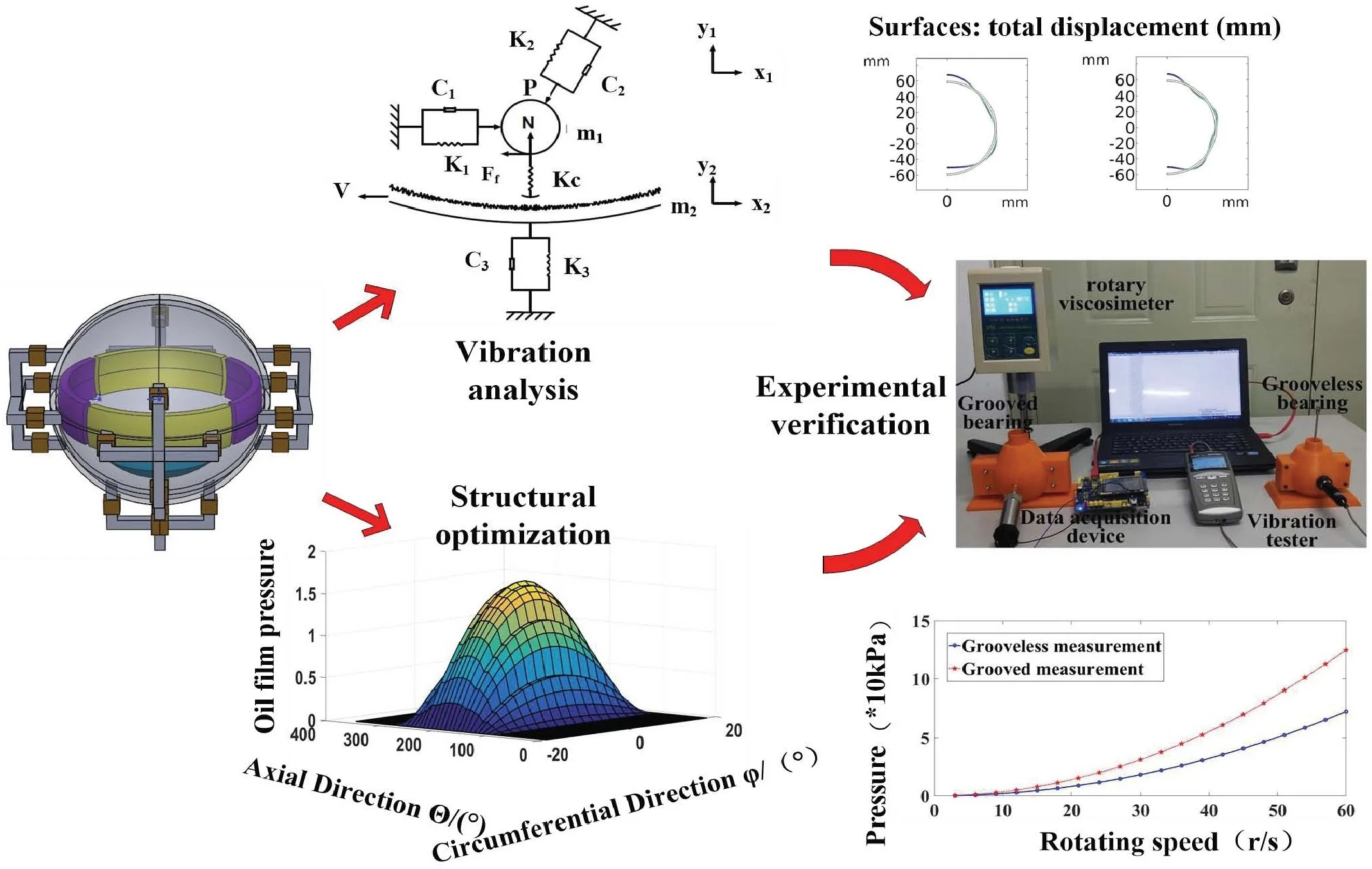
In this paper, based on the analysis of the characteristics of rough surface morphology, an optimized structure with spiral grooves is proposed. The influence of oil film pressure distribution, oil film thickness distribution and different eccentricity on the performance of the optimized spherical motor lubricating oil was calculated by the finite difference method. Then, the static and dynamic performance results of the system are given. The feasibility of the optimal design of the stator spiral groove is determined. Finally, the theoretical basis for further optimization of bearing lubrication performance is verified by experiments.
2. Structure and working principle of motor
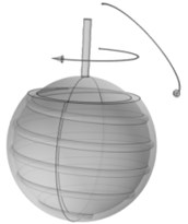
The structure of liquid suspension multi-degree-of-freedom spherical motor is shown in Fig. 1, which is mainly composed of rotating working structure and supporting structure of the motor. The rotating structure of the motor is composed of the four pole patch ring main permanent magnet and the corresponding claw shaped distribution coil winding distributed at the equator of the spherical motor, and the permanent magnet and tail coil winding are fine tuned [1, 2]. The structure of the liquid suspension spherical motor with multiple degrees of freedom is shown in Fig. 1(a), which is mainly composed of the rotating working structure and supporting structure of the motor.
As shown in Fig. 1(b), the main coil and the main permanent magnet are set at the equator of the spherical rotor spherical shell. There are four permanent magnets in this part, and the polarity of the permanent magnet is set as N-pole and S-pole alternately arranged. The claw shaped core and coil are evenly distributed outside the stator spherical shell, and correspond to the distribution position of the permanent magnet. The auxiliary permanent magnet is installed at the bottom of the rotor spherical shell, and the tail coil installed at the end of the stator shell forms the fine adjustment device of the motor. The structure of the motor is listed in Table 1.
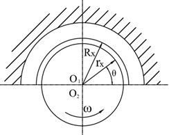
The spherical bearing structure is composed of the stator spherical shell and the rotor spherical shell of the motor. The clearance between the stator spherical shell and the rotor spherical shell is filled with lubricating liquid to provide lubrication and support for the rotor during rotation. As shown in Fig. 2, when the rotor rotates in the stator housing, the adjacent lubricating oil enters into the gap of convergence wedge, and the compressed lubricating oil produces dynamic bearing capacity, so that the stator housing and the rotor housing are separated and bear external loads.
Fig. 1Motor structure diagram
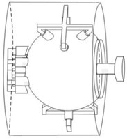
a) Overall wiring diagram of motor
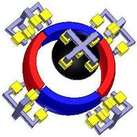
b) Electromagnetic structure diagram
Table 1Structural parameters
Parameter name | Parameter values | Parameter name | Parameter values |
Stator Lam Dia | 30 / mm | Rotor Outer Diameter | 24 / mm |
Stator Bore | 28 / mm | Rotor wall thickness | 2 / mm |
Bearing clearance | 1 / mm | Helical angle | 15° |
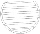
Spiral parts are a very common structure, which can be used in spherical bearings to enhance the transfer of motion and power. While reducing the friction resistance of transmission, the larger load is driven by smaller power. The spiral groove with a starting angle of 15 degrees is excavated inside the outer ring spherical shell. In order to ensure the multi-degree of freedom operation of the ball bearing, the top of the outer ring spherical shell is removed. The structure schematic diagram is shown in Fig. 2.
Fig. 2Schematic diagram of spiral groove structure of spherical bearing of 3-DOF motor
3. Modeling
3.1. Elastohydrodynamic lubrication model for spherical bearing of motor
The working principle of ball bearing of spherical motor is similar to that of rolling bearing. In the structure of spherical bearing, lubrication theory and elastic contact theory are combined, that is, fluid solid coupling theory.
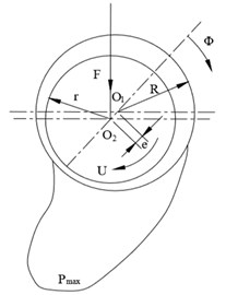
As shown in Fig. 3(a) bearing cross section, the relative movement of the stator and rotor surface of the spherical motor causes lubricant to enter into the spiral groove, forming a pressure in the arc clearance of the groove to bear the external load. For any part of the clearance, the film pressure has a convex distribution. The oil film thickness of the model is discrete, and the oil film is simplified as a combination of several thin cylinders with different radii. The th section of bearing eccentricity is shown in Fig. 3(b). When the ball bearing works, only the spherical surface covered by the stator spherical shell bears the load, so the lubricating film is generated in this area.
Fig. 3Working section diagram of bearing
a) Bearing section diagram
b) Bearing eccentricity section
In Fig. 3 represents the bearing center, represents the bearing journal center, represents the maximum oil film pressure, represents the speed, represents the oil film angle, the geometric center eccentricity of bearing inner and outer rings , the radius clearance of stator and rotor , represents the eccentricity, represents the bearing capacity.
The supporting structure of spherical motor has the same structural characteristics as spherical bearing. Combining with the basic laws of fluid flow: mass conservation law, energy conservation law and momentum conservation law, i.e. N-S equations, the fluid-solid coupling analysis based on structural mechanics can be considered as a linear structure under small deformation [14, 15].
According to the fluid-solid coupling theory, the viscous incompressible flow field of the inner-ring spherical rotor is described by three-dimensional Reynolds Eq. (1):
Among them, represents oil film pressure, represents bearing clearance, represents rotate speed of bearing rotor, represents oil film viscosity of lubricant, and , represents coordinates of points in rectangular coordinate system. The first term on the right side of the equation is used to describe the effect of the lubricant wedge and whirl formed between the rotor rotation and the stator inner wall on the bearing.
The time-dependent term in the Eq. (1) is omitted when the steady-state performance of spherical bearings is analyzed. That is, the constant incompressible Reynolds equation is expressed as Eq. (2):
The dimensionless Reynolds equation of spiral groove for the optimized model is expressed as Eq. (3):
For spherical bearing calculation and analysis process, spherical coordinate system is selected to solve Reynolds equation to obtain more accurate results. The Reynolds Eq. (4) in spherical bearing is obtained by transforming rectangular coordinate system into spherical coordinate system:
3.2. Lubricant film thickness equation for spherical bearing of motor
In Fig. 3, the angle between the section of the th cylindrical thin layer and radius is , and the angle between radius and horizontal plane is :
Therefore, the vertical clearance depth on the inner wall of spherical bearings is expressed as follows:
where, represents the spiral groove depth of spherical bearings.
Because the oil film diameter (equivalent to the diameter of circular cross-section) in the inner and outer ring gap is small and the lubricant has a certain viscosity, the Reynolds number of oil film flow in the gap is small, which generally belongs to the laminar flow range. According to the fluid-solid coupling theory and the model characteristics, the boundary conditions are set as follows:
(1) Solid boundary conditions: The end face of spherical bearing is free, the outer ring is set as a fixed constraint, and the interface between the inner wall of the outer ring and lubricant is a fluid-solid coupling boundary.
(2) Fluid boundary condition: Under lubrication condition, the contact surface between lubricant and outer wall of inner ring is set as non-slip wall, which can reduce friction between inner ring and outer ring through fluid-solid coupling boundary.
(3) Hypothesis of fluid: The fluid studied and experimented is incompressible Newtonian fluid, and the lubrication film is very thin, so the viscous motion of the liquid in the clearance is dominant, so the mass of the fluid is neglected. Compared with the viscous force of the lubricating medium, the inertia force and the centrifugal force of the oil film bending are neglected.
3.3. Theoretical model of surface roughness
The contact force between the stator and rotor surfaces with different roughness is usually complicated by various factors, resulting in mechanical deformation and reaction coupled motion, which increases the asymmetry of contact force.
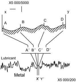
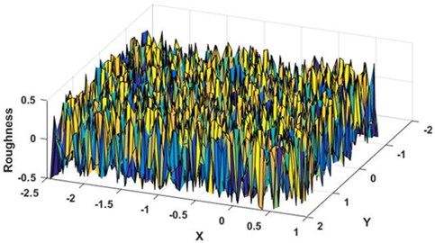
The height of rough surface of stator and rotor of spherical motor is a random and non-stationary process, so the statistical parameters of the surface characterization are scale-dependent. Majumdar and Bhushan have proposed that rough surfaces in engineering applications can only be characterized by fractal dimension, as shown in Fig. 4 [23].
Rough surface profile is characterized by Weierstrass - Mandelbrotfunction [24-26]:
where, represents scale constant, represents fractal dimension, , is reciprocal of roughness wavelength. is a multiscale function consisting of the superposition of infinite frequency modes. Its multiscale properties are shown by the power spectrum of the function. The amplitude of roughness is provided by the power spectrum at all length scales:
where denotes frequency.
For actual rough surfaces, the scaling constant in Eq. (8) can be derived from Eq. (9) of known . At the same time, Weierstrass-Mandelbrot function representing rough surface is obtained. From the Eq. (8), it can be seen that Weierstrass-Mandelbrot function is similar to Fourier series, but the frequency increases in geometric series rather than arithmetic series.
Fig. 4Schematic diagram of motor surface roughness
3.4. Theoretical model of spherical bearing vibration
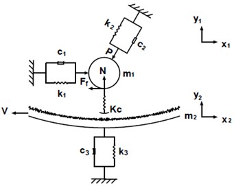
Because the disturbance of random rough surface of spherical bearings cannot be neglected, the vibration model of spherical bearings under combined radial and axial moment loads is simplified by the generalized three-degree-of-freedom coupled vibration model for three-degree-of-freedom motors as shown in Fig. 5. Because the lubricating oil film formed in the working process of spherical bearings has the bearing capacity, but the grease also has the viscosity, so the oil film also has the damping effect, so it is equivalent to the elastic support in parallel with the damping device.
In the Fig. 5, , represent the rotor, stator mass, , and represent the horizontal, inclined, vertical stiffness, , and represent the horizontal, inclined, vertical damping coefficients, represents the contact stiffness coefficient of stator and rotor, represents the corresponding friction force, represents the normal support force of spherical bearings, and are respectively the loudness velocity and friction coefficient of stator and rotor.
When the motor is stationary, the three-degree-of-freedom vibration system does not undergo elastic deformation, and the rotor is subjected to pressure from the oil film. The relationship between friction and bearing normal support force is expressed by Coulomb’s law.
The vibration equation of the system can be expressed as:
where, represents the mass matrix of the stator and rotor, represents the damping coefficient matrix, represents the stiffness coefficient matrix:
where, represents the same angle as shown in Fig. 3.
Fig. 5Elastohydrodynamic contact vibration model of spherical bearing
Nonlinear elastic deformation between stator and rotor occurs when spherical bearing is loaded due to rough surface disturbance and radial electromagnetic harmonics of motor. The equivalent stiffness of oil film between stator and rotor is an important element in studying the vibration characteristics of spherical bearings during deformation during operation. In the working process of spherical bearing, the viscous lubricating oil is affected by the shear force produced by rotor rotation, forming elastohydrodynamic. According to the characteristics of Elastohydrodynamic lubrication, the stiffness of lubricating oil film of bearing is determined by the minimum film thickness when neglecting the influence of temperature on the viscosity of lubricating oil [27-30]:
where, represents the speed of the rotor, represents the viscous-pressure coefficient of the lubricant, represents the elastic modulus of the lubricant, represents the load of the bearing, represents the eccentricity of the bearing rotor.
The oil film thickness between the stator housing and the rotor is expressed as follows:
Spherical bearings are rolling bearings. Therefore, the stiffness of lubricating oil film is the load required to produce unit displacement in the axial direction of the bearing:
where, represents the contact load of the bearing.
The spherical spiral groove bearing model is established in the multi-physical field simulation software (COMSOL). The model structure is divided into two parts: outer-ring spherical shell and inner-ring rotor. The spiral groove used as the oil chamber is located inside the stator wall and the top of the outer ring spherical shell is removed. A liquid suspension structure is formed between the integral spherical shell of the outer ring and the inner ring, which is supported by a lubricating medium. In the simulation software, the laminar flow physical field and solid mechanics physical field of rotating machinery are selected to calculate the pressure distribution of spherical shell and spiral groove outside oil film of spherical bearing. The compressibility of fluid chooses incompressible fluid, and the boundary condition of inner wall is wall-free sliding.
The load-bearing capacity of spherical motor is reflected by the pressure of oil film. The load-bearing capacity of motor is proportional to the pressure of oil film. When the oil film pressure of motor reaches a stable state, it presents elastohydrodynamic lubrication. When the pressure of lubricating oil film is too high, the oil film will break. At this time, it is easy to make the stator and rotor of the motor contact directly, resulting in friction and wear of the bearing. Therefore, the continuity of the pressure oil film formed during the operation of the motor is very important.
4. Analysis of calculation result
4.1. Roughness calculation and oil film analysis
Fig. 6 shows the surface roughness distribution of spherical motor with roughness of 0.1. If the roughness amplitude is increased, the calculation results will not converge. At this time, with the increase of roughness amplitude, the oil film pressure will also increase, resulting in oil film rupture, contact surface wear and vibration increase, rapidly reducing the life and working accuracy of the spherical motor.
Fig. 6Calculates rough surface distribution
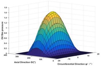
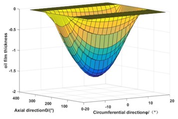
By establishing the analysis model of spherical bearing, taking the parameters affecting the bearing performance and oil film thickness as variables, changing the parameters, analyzing the changes of various indicators of spherical bearing. Through the above theoretical analysis, the smooth inner spherical bearing and groove bearing are calculated and studied by programming software. By keeping the speed and load constant, according to Eq. (3), the dimensionless pressure distribution of the lubricating oil film and the dimensionless oil film thickness distribution of the spiral groove structure are shown in Fig. 7(a, b).
The oil film pressure of spherical motor with slot structure increases obviously with the distribution pressure of spiral groove. The thickness of oil film increases at the spiral groove because of slot structure, which ensures the continuity of oil film and good lubrication performance, and helps to reduce the low frequency vibration of bearing caused by the non-linear change of oil film stiffness.
Under the actual working conditions of spherical motor, the bearing eccentricity varies with the load. As shown in Fig. 7(c, d), the relationship between film pressure and eccentricity of grooved structure and grooveless structure is shown. When the eccentricity is 0.2, 0.4, 0.6 and 0.8, the oil film pressure on the axial distribution increases with the eccentricity, and the dimensionless pressure of the lubricating film increases accordingly. In the main bearing area of spherical bearings, the difference is that the maximum oil film pressure along the axis of groove structure is larger, so the bearing capacity is stronger. Thus, the spiral groove enlarges the bearing capacity width of the axial oil film. It improves the bearing capacity of sliding bearings and reduces the flow rate of lubricating oil and friction coefficient.
Fig. 7Oil film pressure and thickness distribution
a) Three-dimensional oil film pressure distribution of grooved bearing
b) Three-dimensional oil film thickness distribution of grooved bearing
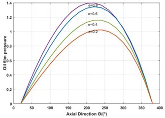
c) Pressure distribution of oil film with different eccentricity in grooveless axial direction
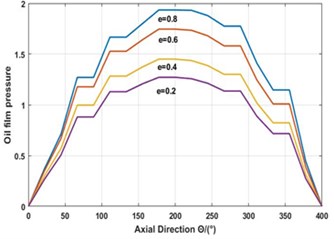
d) Oil film pressure distribution of grooved bearing under different eccentricity
4.2. Analysis of vibration characteristics of spherical bearings
The coupling mode of fluid domain and solid domain is fully coupled to ensure the complete coupling of physical processes in the simulation process. It combines the fluid equation with the solid mechanics equation. The surface roughness value of stator and rotor is 0.1, and the same solver is used. The spiral groove is subdivided by high precision mesh, which improves the convergence accuracy of the calculation results.
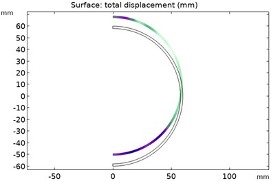
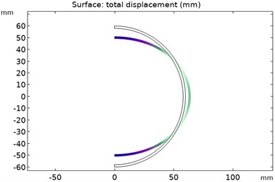
The distribution of modal force wave of the rotor of order 1-6 is shown in Fig. 8. The spherical shell of the rotor is deformed by the pressure of the oil film. The deeper the color, the greater the deformation of the oil film. In the 1-6 modes, the positions with the largest deformation value of the outer wall of the rotor are located at the top and bottom of the rotor. However, the deformation law of the rotor spherical shell follows the mode shapes of various modes.
Compared with the spiral groove structure, the velocity vector distribution of oil film without spiral groove is offset due to the static eccentricity of the rotor, as shown in Fig. 8. Especially when the bearing starts from the initial state, the spiral groove structure helps the oil film velocity transmission to rise uniformly along the spiral groove, which can effectively avoid the interference of the non-uniform oil film thickness on the vibration of the spherical bearing caused by the oil film velocity offset. Moreover, the average oil film thickness is increased by adding spiral grooves, and a more reliable rotor-support system is formed. The elastic support supported by oil film can allow the three-degree-of-freedom motor with liquid suspension to work at relatively high rotational speeds, while reducing the same probability of rotational speed as the critical flexural speed.
Fig. 8Force wave distribution of rotor modes of order 1-6
a) Force wave distribution of the first order rotor mode
b) Force wave distribution of the second order rotor mode
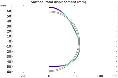
c) Force wave distribution of the third order rotor mode
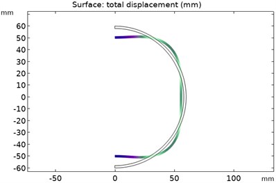
d) Force wave distribution of the 4th order rotor mode
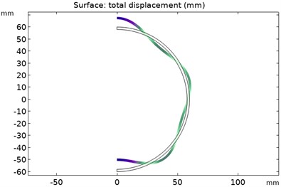
e) Force wave distribution of the 5th order rotor mode
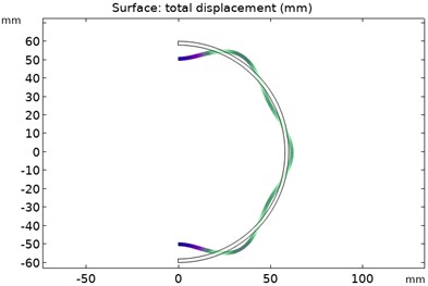
f) Force wave distribution of the 6th order rotor mode
Fig. 9(a) shows the periodic distribution of oil film damping force and elastic force. The vibration system of spherical bearings moves periodically under the action of elastic force and damping force. Damping force can consume the vibration energy of the system. The effect of damping on the vibration amplitude is reflected in Fig. 9(a). Fig. 9(b) is a time-dependent comparison of the damping force and the elastic force of the lubricating film. Rotor rotation transfers speed to oil film through shear force. The elastic force produced by oil film is the bearing capacity of spherical bearing. Although the oil film resistance of grooveless bearings decreases gradually with the increase of oil film velocity, the maximum load-carrying capacity of grooveless bearings is not as strong as that of spiral grooved bearings. The spiral groove structure can ensure the increase of oil film pressure and the stability of oil film. The increase of damping force is due to the formation of oil film squeezing caused by rotor rotation and oil wedge rising along the spiral groove sphere. The distribution of damping force and elastic force of lubricating oil film with spiral groove structure is more in line with the periodic law of damping vibration.
Fig. 9Oil film velocity vector distribution
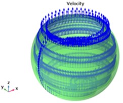
a) Film velocity vector with spiral groove
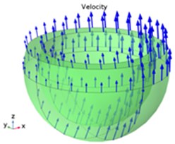
b) Film velocity vector without spiral groove
In the initial state of the rotor, the vibration displacement of the stator spherical shell fluctuates obviously due to the unstable elastic force and damping force of the oil film, as shown in Fig. 10(c). The spiral groove structure can effectively reduce the vibration displacement of the stator spherical shell when the rotor rotates initially. Fig. 10(d) shows that the stators of two structures are subjected to pressure distribution from the oil film. The pressure amplitude of stator spherical shell with spiral groove structure increases, and the damping periodicity becomes more obvious in the same time, which indicates that the damping effect of lubricating oil film increases after adding spiral groove.
Fig. 10Computational results of force and vibration of the system
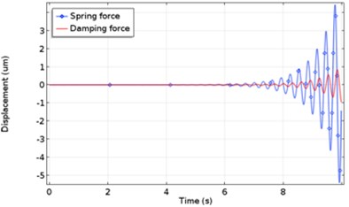
a) Periodic distribution of oil film damping force and elastic force
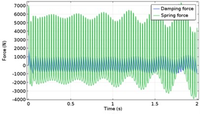
b) Time-dependent comparison of damping force and elastic force of lubricating film
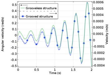
c) Vibration velocity comparison of two structures
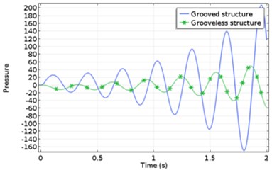
d) Pressure comparison between two structures
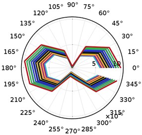
When the rotor rotates, the variation of the axial vibration displacement of the stator with time is shown in Fig. 11. The amplitude of the vibration displacement of the stator is combined with the corresponding phase in polar coordinates. It can be clearly understood that the relationship between the position of the spiral groove and the vibration displacement is not available from 345 to 0 because the shape of the stator shell is multi-hemisphere, and the vibration near each spiral groove is relatively stable.
Fig. 11Distribution of stator displacement in polar coordinates
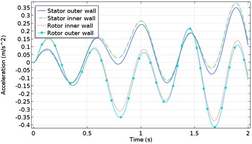
The stiffness of lubricating oil film can directly reflect the bearing capacity of spherical motor. The oil film stiffness varies nonlinearly with the increase of roughness amplitude. The maximum oil film stiffness lies near the center of the contact zone. The uneven distribution of oil film thickness will seriously affect the stability of the spherical motor.
Fig. 12Vibration acceleration of stator rotor shell
5. Experimental verification
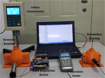
According to the simulation results of the two motor models, the test platform is built as shown in Fig. 13. The testing device mainly includes rotary viscometer, vibration tester, data acquisition device, lubricant, etc. The rotor spherical shell of the spherical motor is installed in the stator spherical shell. The rotating viscometer shaft is connected with the rotor spherical shell. The rotating shaft is enclosed with a sealing ring to avoid the outflow of lubricating oil, thus meeting the sealing requirements of spherical bearings. The inner rotor is set with different speed by viscometer to ensure the average speed is basically stable. The outer surface of motor stator shell is equipped with oil intake holes, and the injected lubricant enters the clearance between stator and rotor spherical shell, thus filling the space between stator and rotor spherical shell with lubricant. The inner wall pressure values of the two models were measured. The pressure measurement points are set at the same position of the two models, and the pressure values of the two models under different rotational speeds are compared and analyzed by using the control variable method. As shown in Fig. 14, when the speed is low, the lubricant film pressure rises to the middle position of the outer spherical shell, and the film pressure increases as the speed increases gradually. Longitudinal comparison shows that the pressure of lubricant film with spiral groove structure is 45 % higher than that without groove structure. The pressure of oil film can be directly related to bearing capacity, which verifies the feasibility of grooved structure.
Fig. 13Experimental device
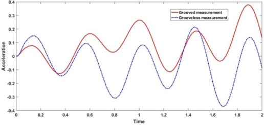
At the same time, the vibration acceleration of two kinds of model rotors is measured, and the comparison chart of vibration acceleration measurement in Fig. 15 is obtained. Similar to the spiral groove structure, the dynamic pressure effect of inner-ring rotors causes the dimensionless oil film pressure to rise rapidly, there is a certain pressure difference between the grooved oil chamber and the grooveless area, and the processing accuracy of stator and rotor cannot meet the requirements of surface roughness, which results in the periodic deviation of measuring vibration acceleration. Nevertheless, it is clear that the periodic variation of the vibration acceleration of the structure with spiral grooves is observed. The feasibility of spiral groove ball bearing is proved by the experimental results. It provides a useful theoretical basis for the next step of optimizing the design of motor ball bearing to reduce vibration and lubrication performance.
Fig. 14The effect of rotational speed on pressure
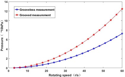
Fig. 15Comparison of vibration acceleration measurements
6. Conclusions
Based on the fluid structure coupling theory analysis and simulation calculation, the influence of spiral groove structure on the lubrication and vibration characteristics of spherical bearing is studied. The distribution law of the rough surface of spherical bearing is calculated and analyzed by program analysis method. Moreover, the dimensionless pressure distribution and the dimensionless film thickness distribution of the oil film with the spiral groove structure are calculated by the analytical method. Secondly, the oil film pressure distribution with different eccentricity was compared. With the increase of eccentricity, the oil film pressure of spherical bearing with spiral groove structure is higher than that without spiral groove structure. Then, the vibration system composed of the stator, rotor and lubricating oil film of the ball bearing is simplified as the vibration coupling model of three degrees of freedom, which are vertical, horizontal and inclined. With the addition of the spiral groove structure, the damping force and elastic force of the lubricating film of the ball bearing increase steadily with time, and the deformation acceleration of the stator is larger than that of the rotor. The lubrication performance and vibration reduction performance of the spherical motor with spiral groove structure on the inner wall of the outer stator spherical shell are better than those without groove structure, and the vibration acceleration stability of the motor is better than that of the smooth ball bearing under the same working conditions. It provides a good theoretical basis for practical application and further optimization design.
References
-
Li Z., Nie Y. M., Xue Z. T., et al. Calculation and analysis of electromagnetic characteristics of liquid suspended three-DOF motor. Journal of Electric Machines and Control, Vol. 21, Issue 4, 2017, p. 44-52.
-
Li Z., Wang Y. T., Rongliang G. E., et al. Summary of research progress on permanent magnet spherical multi-degree-of-freedom motor. Micromotor Journal, Vol. 44, Issue 9, 2011, p. 66-70.
-
Muzakkir S. M., Hirani H., Thakre G. D., et al. Tribological failure analysis of journal bearings used in sugar mills. Engineering Failure Analysis, Vol. 18, Issue 8, 2011, p. 2093-2103.
-
Shah D. S., Patel V. N., Darji P. H. Experimental vibration studies of deep groove ball bearings having damaged surfaces. Journal of The Institution of Engineers (India), Vol. 100, 2019, p. 919-935.
-
Li S. B., Ao H. R., Jiang H. Y., et al. Lubrication characteristics of deep cavity conical hydrostatic hybrid bearings. Journal of Harbin Institute of Technology, Vol. 45, Issue 1, 2018, p. 60-66.
-
Lin Q., Wei Z., Wang N., et al. Analysis on the lubrication performances of journal bearing system using computational fluid dynamics and fluid-structure interaction considering thermal influence and cavitation. Tribology International, Vol. 64, Issue 3, 2013, p. 8-15.
-
Guo L. B., Wang Z. W., Sun A. Structural parameter design of small hole throttle static pressure gas ball bearing. Journal of Harbin Institute of Technology, Vol. 37, Issue 11, 2005, p. 1595-1598.
-
Chen G., Qu M. Modeling and analysis of fit clearance between rolling bearing outer ring and housing. Journal of Sound and Vibration, Vol. 438, 2019, p. 419-440.
-
Flores P. Modeling, Analysis and Simulation of 3D Elastohydrodynamic Revolute Joints in Multibody Systems. Multibody Mechatronic Systems. Mechanisms and Machine Science, Springer, Cham, Vol. 25, 2015.
-
Kasat G. R., Khopkar A. R., Ranade V. V., et al. CFD simulation of liquid-phase mixing in solid-liquid stirred reactor. Chemical Engineering Science, Vol. 63, Issue 15, 2008, p. 3877-3885.
-
Ye Z. Y., Zhang W. W., Shi A. M. Fluid-solid Coupling Mechanics Foundation and Its Application. Harbin Institute of Technology Press, Harbin, China, 2010, p. 36-42.
-
Li K., Liu J., Han X., et al. Identification of oil-film coefficients for a rotor-journal bearing system based on equivalent load reconstruction. Tribology International, Vol. 104, 2016, p. 285-293.
-
Xiang L., Hu A., Hou L., et al. Nonlinear coupled dynamics of an asymmetric double-disc rotor-bearing system under rub-impact and oil-film forces. Applied Mathematical Modelling, Vol. 40, Issues 7-8, 2016, p. 4505-4523.
-
Xiang L., Hou L. Feature analysis of interaction on rub-impact and oil-film faults for a rotor-bearing system. 12th International Conference on Ubiquitous Robots and Ambient Intelligence, 2015, p. 246-254.
-
Zhang Y. Q., Kong X. B., Guo L. L., et al. Simulation and experiment of starting transient flow field of the hydrostatic bearing based on dynamic mesh method. High Technology Letters, Vol. 23, Issue 3, 2017, p. 298-305.
-
Aditya Sharma, Amarnath M., Pavan Kumar Kankar Use of feature ranking techniques for defect severity estimation of rolling element bearings. International Journal of Acoustics and Vibration, Vol. 23, 2018, p. 49-56.
-
Jin G. Y., Su Z., Ye T. G., Jia X. Z. Three-dimensional vibration analysis of isotropic and orthotropic conical shells with elastic boundary restraints. International Journal of Mechanical Sciences, Vol. 89, 2014, p. 207-221.
-
Amabili M., Arziera R., Negri A. Experimental study on large-amplitude vibrations of water-filled circular cylindrical shells. Journal of Fluids and Structures, Vol. 16, Issue 2, 2002, p. 213-227.
-
Li Hui, Luo Haitao, Sun Wei, Wen Bangchun The influence of elastic boundary on modal parameters of thin cylindrical shell. International Journal of Acoustics and Vibration, Vol. 23, Issue 1, 2018, p. 93-105.
-
Malekzadeh P., Golbaharhaghighi M. R., Atashi M. M. Free vibration analysis of elastically supported functionally graded annular plates subjected to thermal environment. Meccanica, Vol. 46, Issue 5, 2011, p. 893-913.
-
Zhao Chunlian Research on Vibration of Ball Bearing. Zhejiang University, Zhejiang, China, 2003.
-
Lin C. G., Zou M. S., Sima C., Liu S. X., Jiang L. W. Friction-induced vibration and noise of marine stern tube bearings considering perturbations of the stochastic rough surface. Tribology International, Vol. 131, 2019, p. 661-671.
-
Zhu Z. Q., Xia Z. P., Wu L. J., et al. Analytical modeling and finite-element computation of radial vibration force in fractional-slot permanent-magnet brushless machines. IEEE Transactions on Industry Applications, Vol. 46, Issue 5, 2010, p. 1908-1918.
-
Lim C. K., Chen I. M., Yan L., et al. Motion generation methodology of a permanent magnet spherical actuator. International Conference on Advanced Intelligent Mechatronics, 2009, p. 1377-1382.
-
Du G. H., Huang N., Zhang F. G., et al. Modal analysis of the flexible rotor system for high-power high-speed permanent magnet machine. Transactions of China Electrotechnical Society, Vol. 32, Issue 22, 2017, p. 101-107.
-
Marcellin Zahui, Rohan Thomas Beam vibration displacement curve measurement. International Journal of Acoustics and Vibration, Vol. 22, Issue 1, 2017, p. 111-120.
-
Pedro Souza R. C., Anderson Proenca R., Odenir De Almeida, Self Rodney H. Aerodynamics and aeroacoustics investigation of a low speed subsonic jet. International Journal of Acoustics and Vibration, Vol. 22, Issue 1, 2017, p. 121-130.
-
Serra R., Rmili W. Experimental evaluation of flank wear in dry turning from accelerometer data. International Journal of Acoustics and Vibration, Vol. 21, Issue 1, 2016, p. 50-58.
-
Sun Z. J., Hou L., Chang Q. L., Wei Y. Q. Nonlinear torsional vibration modeling and characteristic study of planetary gear train processing device. International Journal of Acoustics and Vibration, Vol. 21, Issue 1, 2016, p. 59-66.
-
Marcelo Bustamante, Gerges Samir N. Y., Vergara Erasmo F., Arenas Jorge P. High damping characteristics of an elastomer particle damper. International Journal of Acoustics and Vibration, Vol. 21, Issue 1, 2016, p. 112-121.
About this article

This research was funded by the National Natural Science Foundation of China, grant No. 51877070, 51577048, the Natural Science Foundation of Hebei Province of China, grant No. E2018208155, the Talent Engineering Training Support Project of Hebei Province, grant No. A201905008, the National Engineering Laboratory of Energy-saving Motor and Control Technique, Anhui University, grant No. KFKT201901, Hebei Province Higher Education Science and Technology Research Key Project, grant No. ZD2018228.
