Abstract
Functioning of the universal rocket transportation launching device in its transportation mode is analysed in the paper. The device the main function of which is to launch rocket targets used in the training process of the anti-aircraft missile systems operators needs to function effectively in transportation mode as well – it has to move with relatively high speeds in training fields maintaining sufficient stability parameters of the rocket target movement. The universal rocket transportation launching device in transportation mode is modeled as a single axle trailer with a rocket target – long cylinder attached to it by suspension represented in the form of lumped parameter elastic damping elements. Dynamical models for the analysis of its vertical and roll motion dynamics were constructed and the corresponding mathematical models derived. The excitation signal reconstructing motion of the wheels traversing discrete cleats was applied. Crossing of the longitudinally shifted left and right-side cleats was identified as the worst case from the viewpoint of rocket target motion parameters stability. The obtained results are used for rocket target suspension development.
1. Introduction
The universal rocket transportation launching device is developed as a platform for launching rocket air targets to be used in training process of anti-aircraft missile systems operators. It was developed for operation in launching mode and in transportation mode. Structurally the universal rocket transportation launching device is a single axle trailer and rocket launching system attached to it. The rocket air target is transported in horizontal position. Suspension elements of the rocket air target have to guarantee its reliable attachment to the frame of the trailer and prevent from too high loads on the rocket body when moving on training field terrain, i.e.at rough road conditions with discrete cleats with relatively high speeds.
The universal rocket transportation launching device is intended to be towed by a tractor vehicle which can develop sufficient power to move at high speeds on rough road conditions or even off road, not losing stability of motion and preserving the transported object (in the case under analysis the rocket transported in horizontal position) from too high loads on it.
Dynamical systems of the similar structure – tractor vehicle – trailer was analyzed the most widely in researches for agricultural applications [1], for transportation of particle type materials by dumping trailers [2, 3] for the development of automatic guiding systems in agricultural machinery.
Therefore, it can be concluded roll motion stability and vertical dynamics of the system consisting of a tractor vehicle and single axle trailer is not sufficiently deeply researched in order to develop rocket air targets transportation system effectively functioning on rough roads or off road with clearly expressed discrete obstacles.
In the current research vertical dynamics of the universal rocket transportation launching device at rough road or off-road conditions where the highest loads on the rocket body are generated and roll motion characteristics are being analyzed.
1.1. Theoretical background
As the most typical situations, crossing of discrete (cleats) obstacles by trailer wheels and associated with this, dynamical characteristics of vertical motion of the rocket body as well as roll motion of the trailer system when crossing a cleat and the possibility to loose stability were analyzed in the current research.
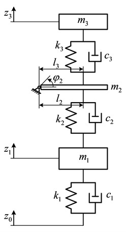
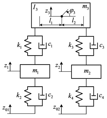
Lumped parameter half vehicle model created for the analysis of vertical dynamics is shown in Fig. 1, and roll motion characteristics of the frame of the device were analyzed with use of 2D, lumped parameter model shown in Fig. 2.
Fig. 1Half vehicle model of the universal rocket transportation launching device

Fig. 2Perpendicular plane 2D model of the universal rocket transportation launching device

The following assumptions were made: a discrete single obstacle is crossed without losing forward velocity due to sufficient power of the towing vehicle; the trailer frame is free to pivot about hooking point to the tractor; pivot point maintains constant vertical coordinate; wheels of the trailer roll in free mode [4], i.e. traction force acts at rotation axis of the wheel, no external (driving or braking) moments are applied. Then equations of motion for half vehicle model (Fig. 1) are as follows:
where – unsprung mass, – sprung mass, – mass of the rocket target, , – resultant stiffness and damping coefficients of the right and left tires, , – stiffness and damping coefficients of the trailer suspension, , – stiffness and damping coefficients of the rocket suspension, – total mass moment of inertia of the trailer and the rocket with respect to the pivot point of the hooking device, – the distance of wheel axis from pivot point, – distance of the frame mass center from the pivot point, , , – vertical coordinates of wheel-road contact point, wheel axis, rocket mass center accordingly, – angular coordinate of the unit’s frame.
For roll motion analysis of the rocket frame, mathematical model is derived:
where and are unsprung masses of right and left wheels stations accordingly, – total sprung mass representing the trailer frame and the rocket, – total mass moment of inertia of the trailer and the rocket with respect to the center of gravity, , and , – stiffness and damping coefficients of the right and left tires accordingly, , and , stiffness and damping coefficients of the wheel stations.
1.2. Simulation results and discussion
Pulse type input signals representing the process of traversing of a single discrete obstacle in the form of rectangular cleat by a wheel or traversing several cleats shifted one with respect to another along the forward motion axis are considered as dangerous excitation cases from the perspective of trailer motion stability. Following the methodology [5], enveloping properties of the tire were taken into account and its inertia properties neglected.
Fig. 3Vertical velocity of the rocket at different motion velocities of the trailer

Fig. 4Vertical acceleration of the rocket at different motion velocities of the trailer

Fig. 5Angular accelerations of the trailer body at its different motion velocities

Fig. 6Vertical displacement of the rocket when traversing rectangular cleat by right wheel at different motion velocities of the trailer

Fig. 7Angular accelerations of the frame when traversing rectangular cleat by right wheel at different motion velocities of the trailer

Fig. 8Angular displacement of the frame when traversing longitudinally shifted (1s shift in time axis) rectangular cleats by left and right wheels at different motion velocities of the trailer

Fig. 9Angular acceleration of the frame when traversing longitudinally shifted (1s shift in time axis) rectangular cleats by left and right wheels at different motion velocities of the trailer

Simulation of the system behavior was carried out in Matlab Simulink environment. The cases of crossing different height rectangular cleats at different speeds of the unit were investigated. Simulation results of the half vehicle model are presented in Figs. 3-5.
Simulation results of perpendicular plane 2D model are presented in Figs. 6-10.
The graphs on the left column of all the figures represent the case of traversing 0,1 m height cleat, and the right column graphs represent traversing of 0,15 m height cleat.
Vertical displacement, velocity and acceleration of the rocket in transportation position were investigated with the use of half vehicle model and angular displacement, Angular displacement and angular acceleration of the frame with the attached to it rocket target in roll motion mode were investigated with the used of 2 Perpendicular plane 2D model. It is obvious from the obtained simulation results that the motion of the frame – rocket unit is oscillatory and strongly decaying. Therefore, the conclusion that single discrete obstacles (rectangular cleats) of moderate height can be crossed by the universal rocket transportation launching device at relatively high speeds of its motion can be made. Thus, the universal rocket launching device can function effectively in transportation mode moving on a ground of a training field.
2. Conclusions
Mathematical models for the analysis of the characteristics of vertical dynamics and stability in roll motion mode of the universal rocket transportation launching device in case of crossing single discrete obstacles at relatively high its motion velocities were created.
The simulation results revealed that motions of structural parts of the device and the transported air target are oscillatory and strongly decaying therefore the universal rocket transportation launching device can function properly in transportation mode.
The obtained modeling results can be used for the selection of rocket suspension parameters in order to minimize vertical loads on it.
The device can cross single discrete obstacles by one side wheels the obstacles shifted in motion direction by both side wheels at relatively high speeds without stability loss due to roll motion mode.
References
-
Karkee M., Steward B. L. Parameter estimation and validation of a tractor and single axle towed implement dynamic system model. Computers and Electronics in Agriculture Vol. 77, 2011, p. 135-146.
-
Dump Trailer. US Patent 8876216B2, 2014.
-
Dump Trailer. US Patent 8245717B2, 2014.
-
Larin V. Theory of motion of all drive wheeled vehicles. BMSTU Publishing House, Moscow, 2010, p. 391, (in Russian).
-
Pacejka H. Tire and Vehicle Dynamics. Third Edition, Butterworth-Heinemann, 2012, p. 632.
-
Fedaravičius A., Pilkauskas K., Sližys E., Survila A. Universal rocket transportation launching device – performance characteristics analysis. Proceedings of the 19th international conference, 2014, p. 285-289.
About this article
The research is carried out under activities of the Project “Experimental Rocket: Design and Research” funded by the Lithuanian Research Council (Agreement No. S-MIP-17-94).
