Abstract
Compared with other mechanical products, aircraft structures have more rigorous requirements on flying performance, safety, reliability and service life. Based on the finite element method (FEM), the key component of the wing box model is explored in this paper, which provides a reference for the structure design and manufacture of aircraft wing box. The three-dimensional point cloud data of components are obtained by optical measurement systems, the deviation analysis between the point cloud model and the nominal model is carried out as a prerequisite, and then the natural characteristics of the model is analyzed. The results show that 99.15 % of the measured points have deviations within 0.38 mm, which verifies the accuracy of the nominal model. The first six modes are all bending modal shape, and the larger amplitude region mainly occurs in the wing ribs, which means its bending strength should be improved for structure design. Besides, the sixth-mode simultaneously result in front spar, stringer and rib bending vibration.
1. Introduction
Modern aircrafts tend to have higher standards for lightweight, economy and safety, which increasingly popularize the application of composites in the aircraft manufacturing industry [1]. Wing box is the main load-bearing components, and also the most used part of composite materials in the aircraft structures. Therefore, it is essential to explore the mechanical response of the wing box, since it can reflect the performance of the airfoil to a certain extent.
Regarding wing box modeling and mode analysis, Manisha [2] studied manufacturing deviations during the assembly of the wing box, and these deviations had caused the gaps in major splice joints. Luo [3, 4] established the finite element models of wing box by using 3D shell element to investigate the stacking sequence effect on the natural modal and bucking properties. Chen [5] proposed a complex wing box system and studied empirical mode decomposition (EMD) by using the Hilbert-Huang transform (HHT). Baets [6, 7] investigated the sensitivity of the flutter speed, divergence speed and modal response when varying the composite skin lay-up, fiber orientation, and the root flexibility of the model. Ovesy [8] concluded that optimum lay-up configuration had great dependency to the buckling modal shape of the wing box. The existing literature has done many research on the mechanic performance of aircraft structures, but still lack of wing box weakness component considerations. Therefore, this article thoroughly studied the natural characteristics of the aircraft wing box. And based on the large data sets processing, the key components of the wing box are analyzed by FEM.
2. Wing box modeling based on measured data
As shown in Fig. 1(a), the typical composite wing box section is as follows: the wing span length is 1200 mm, the chord length is 1000 mm, the height is 300 mm, and the total weight is about 60 kg. In this paper, FARO Edge 2.7 three-coordinate portable measuring device is used to collect the point cloud data of wing box components (spars, stringers, and ribs), as shown in Fig. 1(b). The collected data is imported into Geomagic software for point clouds pre-processing, as shown in Fig. 1(c)-(f). The point cloud pre-processing mainly includes:
(1) Distorted point removal.
During the measurement, background objects such as the frame may be included, so that single point and noise points around the object could be scanned, and these distorted point clouds need to be deleted.
(2) Data reduction.
The initial number of point clouds can reach more than one million. In order to improve the calculation speed, the point cloud is sampled and processed, and only the necessary point cloud data is retained. Based on the point cloud data characteristics, the curvature-based sampling method can better maintain the point cloud features.
(3) Multi-view cloud points registration.
Since one measurement cannot obtain the complete surface point cloud data of the panel, the spar, or the rib, multiple measurements are conducted to integrate the point clouds into a whole. This can be achieved by fitting the key characteristic points in the overlap area on different point clouds. After large data sets registration we could get the complete point cloud model.
Point cloud data of the components after pre-processing are shown in Fig. 1, in which the upper panel has 4868573 points, spar has 4270265 points, the ribs has 6423380 points, and the lower panel has 3837313 points.
Fig. 1Point cloud measurements
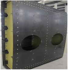
a) Test model
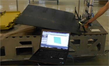
b) Scan measurements
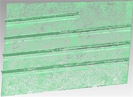
c) Upper panel PC data
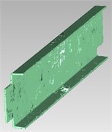
d) Spar PC data
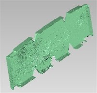
e) Rib PC data
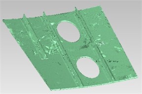
f) Lower panel PC data
The deviation detection process is as follows: the measured PC data is imported into the software together with the nominal model, the nominal model is set as the reference model. The PC model is compared with the reference model by aligning and converting the coordinates of the PC model to the reference coordinate system. The deviation results are shown in Table 1 and Fig. 2. As shown in the deviation distribution, about 98 % of the measured PC data and the nominal model’s position deviation are between –0.05 mm and –0.38 mm, 99.15 % of the measured point deviation is less than 0.38 mm, which verifies the accuracy of nominal model.
Table 1Deviation distribution of point cloud
Maximum deviation | Minimum deviation | Point number | Percentage (%) |
–2.0000 | –1.6750 | 422 | 0.0036 |
–1.6750 | –1.3500 | 417 | 0.0036 |
–1.3500 | –1.0250 | 552 | 0.0047 |
–1.0250 | –0.7000 | 5201 | 0.0443 |
–0.7000 | –0.3750 | 30244 | 0.2577 |
–0.3750 | –0.0500 | 11500602 | 97.9875 |
–0.0500 | 0.0500 | 56179 | 0.4787 |
0.0500 | 0.3750 | 81403 | 0.6936 |
0.3750 | 0.7000 | 35438 | 0.3019 |
0.7000 | 1.0250 | 6048 | 0.0515 |
1.0250 | 1.3500 | 3143 | 0.0268 |
1.3500 | 1.6750 | 968 | 0.0082 |
1.6750 | 2.0000 | 626 | 0.0053 |
3. Mode analysis
Due to the scanning system inevitably has errors in the measurement process, making the finite element analysis model inaccurate. The individual distorted point will seriously reduce the mesh quality of the finite element. Since the modeling accuracy of the nominal model has been verified, therefore, in this paper, the nominal model is used for wing box FEM analysis. In order to save the computational resources and improve the accuracy of the finite element calculation, the hexahedral mesh method is applied in the whole model. Firstly, large area with regular shape is meshed by a certain grid density. Then the grids are refined on the small components such as stringers. The grid size of the panel is defined as 20 mm, the grid size of the front and rear spar is defined as 30 mm, the grid size of the stringer is defined as 10 mm, and the grid size of the ribs is defined as 15 mm. Fig. 2 shows FEM model of the wing box, when the node is 196371 and the element is 38800, the calculation result tends to converge.
Composite materials are widely used in aircraft wing box, such as upper and lower panels, ribs, front and rear spars, those are made of carbon fiber composite materials, the parameters are shown in Table 2.
Fig. 2FEM model of wing box
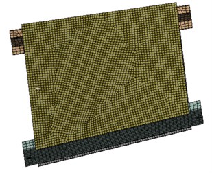
a) Whole wing box
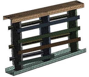
b) Internal structure
Table 2Composite parameters
(GPa) | (GPa) | (GPa) | (GPa) | (GPa) | (GPa) | |||
156 | 8.35 | 8.35 | 4.2 | 4.2 | 2.52 | 0.33 | 0.33 | 0.55 |
(MPa) | (MPa) | (MPa) | (MPa) | (MPa) | (MPa) | (MPa) | (MPa) | (MPa) |
2500 | –1400 | 75 | –250 | 75 | –250 | 95 | 95 | 108 |
The wing box natural frequencies of first six orders are shown in Fig. 3, as is shown in the figure, Fig. 3(a) shows the first-order bending mode of the left wing rib, Fig. 3(b) shows the first-order bending mode of the middle rib, Fig. 3(c) shows the second-order bending mode of the left wing rib, Fig. 3(d) shows the second-order bending mode of the middle wing rib, Fig. 3(e) shows the first-order bending mode of the right wing rib, and Fig. 3(f) is superimposed mode, which means three ribs and front spar display bending modal shape at the same time. In addition, the stringer also bends and lifts the upper panel, but the amplitude is lower than that of the rib. As can be seen from the above figures, the first six modes mainly occur in the rib, and the amplitude is larger. Therefore, materials with larger bending strength may be used in the structure design to prevent the resonance damaging.
Fig. 3The first six natural frequencies of the wing box model
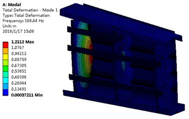
a) First mode
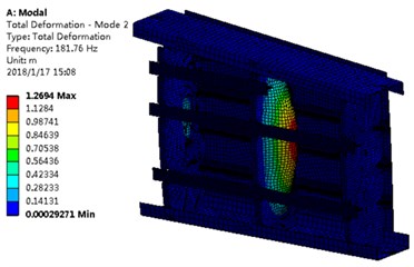
b) Second mode
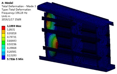
c) Third mode
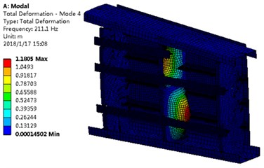
d) Fourth mode
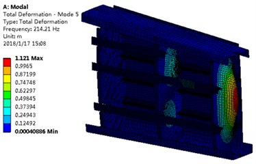
e) Fifth mode
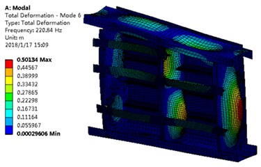
f) Sixth mode
4. Conclusions
In this paper, point cloud reverse processing is carried out on composite aircraft wing box. Deviation analysis between the point cloud model and nominal model are investigated, the natural characteristics of the wing box are analyzed. The conclusions are as follows:
1) 98 % of the measured point cloud data has deviation value –0.05 mm to –0.38 mm compared with nominal model position, which verifies accuracy of the nominal model.
2) Ribs are key component in wing box structure, the first six modes mainly occur in the ribs, and the amplitude is large. Therefore, the material with larger bending strength should be applied.
3) The first six modes are all bending modes, the first mode and the third mode occur in the left rib, the second mode and the fourth mode occur in the middle rib, the fifth mode and the sixth mode occurs in the right wing ribs. These modal shapes could be reference for wing box structure design.
References
-
Burka P. Automated gap analysis and adhesive application during fuselage assembly. Conference Proceedings of the 6th International CFK-Valley Stade Convention, 2012.
-
Manisha B. M., Kotresh G. M., Byji V., Subharao M. Finite element analysis of SARAS wing test box addressing manufacturing deviations. Report Number: PD-AC-0916, 2009.
-
Luo C., Xiong J., Yi X., Zhang Z., Liu G. Natural modal and stability of integrated composite wing box fabricated by RTM process. Acta Materiae Compositae Sinica, Vol. 29, Issue 3, 2012, p. 158-166.
-
Luo C., Xiong J., Yi X., Zhang Z., Bao An J. X., Wang L. Design and manufacture of RTM-made composite wing box based on the water-soluble mandrel. Acta Materiae Compositae Sinica, Vol. 28, Issue 3, 2011, p. 203-209.
-
Chen H., Yan Y., Jiang J. Vibration-based damage detection in composite wingbox structures by HHT. Mechanical Systems and Signal Processing, Vol. 21, Issue 1, 2007, p. 307-321.
-
De Baets P. W., Mavris D. N., Battoo R. S. Aeroelastic analysis of a composite wingbox with varying root flexibility. 41st AIAA/ASME/ASCE/AHS/ASC Structures, Structural Dynamics, and Materials Conference and Exhibit, 2000.
-
De Baets P. D., Mavris D. N. Potential formulation for aeroelastic constraint analysis in a conceptual design environment. 43rd AIAA/ASME/ASCE/AHS Structures, Structural Dynamics, and Materials Conference, 2002.
-
Ovesy H. R. Buckling characteristics of some composite stiffened boxes under longitudinal compression and bending using finite strip approach. 44th AIAA/ASME/ASCE/AHS/ASC Structures, Structural Dynamics, and Materials Conference, Structures, Structural Dynamics, and Materials and Co-located Conferences, 2003.
About this article

This work is supported by Jiangsu Key Laboratory of Precision and Micro-manufacturing Technology Foundation (Grant No. ZAA1400105); China Scholarship Council.
