Abstract
In this paper, cable isolators with applications in the field of vibration and shocks imported into steel structures and isolated equipment are investigated. The aim of this study is to examine the effect of wire rope isolators by combining friction isolators in steel structures, as well as to obtain the seismic response of isolated structures at base, and to investigate the effect of this isolator on the seismic response based on the nonlinear time history analysis which is the method of our research. Incremental Dynamic Analysis (IDA) is used to evaluate the seismic capacity demand of steel moment frames. In the IDA, spectral acceleration at the first-mode period of vibration with 5 percent damping (Sa(, 5 %)) has been used as an Intensity Measure (IM) , which has the less dispersion for far-fault records. The fragility curves of the structures have been presented for different performance levels.
1. Introduction
The wire rope isolators are made up of a set of series of tensile metal stainless steel wire ropes that are kept in the form of a spiral or between the two metals. In addition to its cost-effectiveness, it is flexible in three directions, and is involved in large displacement due to the spiral layout of the cables. In this paper, a new application for wire rope systems in combination with friction isolator systems has been examined and analyzed. In seismic design, structures are characterized by the capacity of the structure under different levels of the earthquake. Then, the seismic demand capacity of the structures under the effects of earthquake excitations from slight to extreme should not exceed the capacities corresponding to different performance levels of operation.
Balaji et al. [1] studied the wire rope isolators for vibration isolated from equipment and structures in 2015. In their study, vibration and shock were used various techniques to predict their harmful effects on equipment and structures. Balaji et al. [2, 3] studied the vertical static stiffness of the wire rope isolators in 2016. The analytical model for static stiffness in the perpendicular direction was investigated by Castellano’s second theory. Vaiana et al. [4] in 2017 examined the behavior of seismic wire rope isolators for lightweight isolated structures at the base. The main objective of this study was to identify the mechanical properties of the wire rope isolators in three levels of drifts which are: small drift, relatively large drift, large drift limited to allow the use of this seismic isolation system for lightweight structures. In the second section of this paper, the analytical restoring stiffness formulas for this wire rope isolator are presented. In the third section, the characteristics of the structural modeling as well as the friction isolator used at the base are also examined. The third section, contain the information of the earthquake records and the Intensity measure (IM). In the results and discussion section the results of IDA and fragility curves are presented. In the end of the fifth part considers the interpretation and review of the paper and the results of the analysis.
2. Wire rope isolator
In this section, modeling of the isolators used in the structure are designed in accordance to FEMA-350 [5] and FEMA-P695 [6]. The cable isolator has inherent and natural damping due to the friction between the wires and a potential restoring force resulting from deformation as well as high resistance to chemical attack and environmental factors. Its all-metal design also exhibits high resistance against temperature rises. The main limitation of the use of wire rope isolators is their vertical loading capacity. Another type of isolator used is the Friction Pendulum Isolator (FPS). FPS are carrying the weight of the structure, as well as its matching with lateral moving of energy loss, is also provided by restoring the force through a proper arrangement of the slippery concave surface.
To model the wire rope isolator, we have considered several formulations which has presented in [1-3] in detail procedure. The spring stiffness of these isolators is a function of the type of cable and its geometry. This isolator can retain their deformations in one or two or three directions of the imported force path as shown in Fig. 1.
Fig. 1a) The cables are in the direction of compression and tensile, b) the cables are twisted or rotated, c) the cables are under shear force [1-3]
![a) The cables are in the direction of compression and tensile, b) the cables are twisted or rotated, c) the cables are under shear force [1-3]](https://static-01.extrica.com/articles/19866/19866-img1.jpg)
a)
![a) The cables are in the direction of compression and tensile, b) the cables are twisted or rotated, c) the cables are under shear force [1-3]](https://static-01.extrica.com/articles/19866/19866-img2.jpg)
b)
![a) The cables are in the direction of compression and tensile, b) the cables are twisted or rotated, c) the cables are under shear force [1-3]](https://static-01.extrica.com/articles/19866/19866-img3.jpg)
c)
2.1. Structural modeling
In this paper, the studied models are Steel Moment Resisting Frame (SMRF). The structure is modeled in PERFORM 3D software; it is a five story steel structure. Structural design is based on UBC [7] criteria as well as P695-FEMA and F350-FEMA [5] is used for the definition of nonlinear response. The soil condition is type Π. The dimensions of the beam and column used in Table 1 is presented. The type of beams are sheet beam and columns are intended for square or BOX. Incremental Dynamic Analysis (IDA) has been done on the structure. Structural properties have been presented in Table 1. The structural analyzes are considered in two directions. At first the structure was rigid on the base and then analyzed with the isolator.
Table 1Specifications of structure
Dimensions | Length (cm) | Width (cm) | Height (cm) | Thickness (cm) | Number of floor | ||
Structural dimensions | 2283 | 1360 | 1630 | 5 | 5 | ||
Material property data. | Weight per unit volume () | Poisson ratio () | Modulus of elasticity () | Minimum yield stress | Minimum tensile strength | Effective yield stress | Effective tensile strength |
kg/cm3 | kg/cm3 | kg/cm3 | kg/cm3 | kg/cm3 | kg/cm3 | ||
0.00785 | 0.3 | 2E6 | 2400 | 3600 | 2700 | 4100 |
2.2. Structural modeling with isolator
Specifications of friction isolator and wire rope isolator: In Section 2, i.e. modeling, there are brief explanations of friction and wire rope isolators. Two different configurations for isolators are also examined. Each FPS consists of a concave sheet up and down. Isolator height is 100 mm. FPS has two slippery curvatures with the same radius. Corresponding to it, an effective radius is considered for this isolator. The concave surface of the back plates is covered with two sheets. The period of isolation system is 2.5 s. The properties of the isolator system are shown in Table 2. Friction properties has been used for FPS as 0.06 and for wire rope is 0.12.
Table 2Specifications of isolators
Type | Seismic isolator, friction pendulum |
Shear behavior | Stiffness and deformation |
53400 | |
0.3 | |
0.00094 | |
534 | |
Type | Seismic isolator, WRI |
97000 | |
0.2 | |
0.00057 | |
9700 |
3. Earthquake records, intensity measure and damage index
In this paper, 10 far-fault records have been selected from FEMA-P695 [6] and used for nonlinear time history analyses. The average spectral is shown in Fig. 2.
The first-mode of spectral acceleration with 5 percent damping Sa(, 5 %) has been used for developing IDA curves. Also, the dimensionless damage index of the maximum drift ratio of relative inter-floor displacement to floor height during nonlinear time history analysis , which is considered as a criterion for general deformation at the different performance levels of structural and non-structural properties, has been used. In accordance with the 350-FEMA Guideline for typical structures, the performance level capacity for Steel Moment Resisting Frames is shown in Table 3. Table 4 is the definition of different performance level.
Table 3Characteristics of the earthquake ground motion [8]
No | Earthquake | Name | MW | PGA (g) | PGV (CM/S) |
1 | Northridge | Beverly Hills | 6.7 | 0.52 | 63 |
2 | Northridge | Canyon Country | 6.7 | 0.48 | 45 |
3 | Duzce Turkey | Bolu | 7.1 | 0.82 | 62 |
4 | Hector Mine | Hector | 7.1 | 0.34 | 42 |
5 | Imperial Valley | Delta | 6.5 | 0.35 | 33 |
6 | Imperial Valley | El Centro Array | 6.5 | 0.38 | 42 |
7 | Kobe, Japan | Nishi-Akashi | 6.9 | 0.51 | 37 |
8 | Kobe, Japan | Shin-Osaka | 6.9 | 0.24 | 38 |
9 | Kocaeli, Turkey | Duzce | 7.5 | 0.36 | 59 |
10 | Kocaeli, Turkey | Arcelik | 7.5 | 0.22 | 40 |
Table 4Components performance levels [6]
St component | Slight | Moderate | Extensive | Collapse |
Drift ratio | 0.007 | 0.015 | 0.025 | 0.05 |
3.1. Incremental dynamic analysis (IDA)
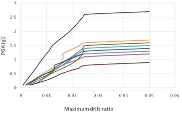
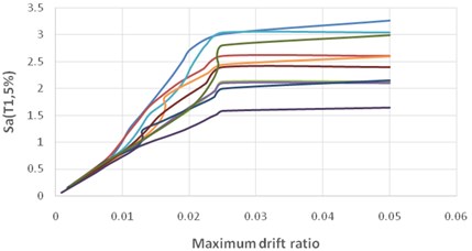
By applying IDA analysis, incremental dynamic curves for 10 far-fault records are depicted for a typical 5-storey structure and isolated at the base. Fig. 2 is the results of IDA curve for five story SMRF with PGA intensity measure and the Fig. 3 is the results with Sa(, 5 %). As its obvious from the figures, the results of Sa(, 5 %) has less dispersion compared with PGA.
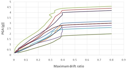
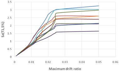
Fig. 4 and 5 shown the same results for the compared intensity measure. Sa(, 5 %) has less depression compared for the both structures.
Fig. 2Multiple IDA curves for far-fault records of a 5-storey SMRF

Fig. 3The summarized IDA curve of far-fault records for a 5-storey SMRF with isolators

Fig. 4Multiple IDA curves for far-fault records of a 5-storey SMRF with isolator

Fig. 5The summarized IDA curve of far-fault records for a 5-storey SMRF with isolator

4. Results and discussions
These fragility curves are shown the probability of structural damage due to various ground excitations. In this paper fragility curves are shown based on PGA as an intensity measure.
By applying the incremental dynamic curves for the studied structures, the following results were obtained based on the Sa(, 5 %) and for far-fault records. Using an isolator proportional to the structure and comparing the incremental dynamic curves, the value of the spectral intensity acceleration index decreases relative to the un-isolated structure. The use of the isolator introduced in the structure increased the period of the structure, significantly reduced the relative drift of the floors, as well as the reduction of the bas shear to the un-isolated structure. In addition, the structures enter the nonlinear stage (in the maximum values of the demand for relative angular relative drift between floors, the results are greater, and the structure is more affected by the input records. Structural elements in the 5-storey building compared to 5-storey isolated building at the base absorbs more energy than the structure, and the elements enter to the nonlinear level more quickly. it is expected that the inertial load distribution will be necessarily linear to the height and the effective height of the inertial force in half the total height. The results of the two structures in the three modes are shown in Table 5. As shown in the table, the rigid structure has a lower period. By adding a friction isolator and wire rope, period of the structure has increased dramatically. Fig. 6 shows the full comparison of fragility curves for mentioned structures. As its obvious the isolation systems works well and increase the capacity of the structure.
Table 5Modal analysis of structures
Type | (sec) | (sec) | (sec) |
Rigid structure | 0.63 | 0.61 | 0.49 |
FPS + WRI structure | 2.27 | 1.45 | 0.23 |
Fig. 6Comparison of fragility curves for different performance level

5. Conclusions
In most regulations for typical buildings with fixed base, it is assumed that the distribution of the inertial load relative to the linear weight and the effects of the first mode on the uniform distribution response are dominant. This distribution has effective height at the center of the triangle, i.e. at a height equivalent to two thirds of the height of the building above the base. This proved correct if the weight of each floor is constant in the structure. The uniform distribution center of inertial loads is in the center of this height. Isolators create principle modes, which are roughly composed of all deformations of the isolator. The studied structures in the maximum demand for relative angular drift between floors of less than 0.025 reach the dynamic instability. Also, in the maximum demand for relative angular drift, it reaches the dynamic instability for isolators in less than 0.4.
References
-
Balaji P. S., Rahman M. E., Moussa L., Lau H. H. Wire rope isolators for vibration isolation of equipment and structures – a review. IOP Conference Series: Materials Science and Engineering, Vol. 78, Issue 1, 2015, p. 012001.
-
Balaji Rahman P. S. M. E., Moussa L., Lau H. H. An analytical study on the static vertical stiffness of wire rope isolators. Journal of Mechanical Science and Technology, Vol. 30, Issue 1, 2016, p. 287-295.
-
Balaji Rahman P. S. M. E., Moussa L., Lau H. H. Static lateral stiffness of wire rope isolators. Mechanics Based Design of Structures and Machines, Vol. 44, Issue 4, 2016, p. 462-475.
-
Vaiana N., Spizzuoco M., Serino G. Wire rope isolators for seismically-base-isolated lightweight structures: Experimental characterization and mathematical modeling. Engineering Structures, Vol. 140, Issue 1, 2017, p. 498-514.
-
Recommended Seismic Design Criteria for New Steel Moment-Frame Buildings. FEMA-350, 2000.
-
Quantification of Building Seismic Performance Factors. FEMA P695, Washington, DC, 2009.
-
UBC-IBC Structural (1997-2000). Comparison an Cross Reference. Intl Code Council, 2000.
-
Next Generation of Ground Motions (Nga) Project. Pacific Earthquake Engineering Research Center, 2017, http://peer.berkeley.edu/nga.
