Abstract
The main goal of this paper is to find stress after the dynamic loading in the spine. At the beginning, it is necessary to obtain a finite element model of the spine where the stress analysis is performed. Two geometries of pathological curvature of spine are analyzed for better understanding of stress distribution in the spine. The next step is to calculate the dynamic coefficient in analyzing the dynamic effects on the spine. Measurements of dynamic effects are done with two types of trainers. In the end the different inclinations of spine in sitting position are compared.
1. Introduction
In this paper we deal with the dynamic loading in the spine. At the beginning, it is necessary to obtain a finite element model of the spine where the stress analysis is performed. The finite element model of a human spine was created from 2D X-ray images of a patient with scoliosis. The procedure of FEM modeling of the spine from 2D images is described in [11].
At the same time, the software for changing the spine geometry was created see Fig. 1. This feature allows to generate a non-scoliotic spine or various other curvatures and spine geometries to compare the effect of changing geometry to the stress. Since we had images of the most common disease of the curvature of spine, the paper first deals with two pathological curvatures of the spine-scholiotic and non-scoliotic. With these geometries, a structural analysis was performed to obtain a better understanding of the effects of the change in spine geometry on stress distribution.
Fig. 1A preview of the software that allows to change the spine geometry: a) Non-scoliotic spine, b) scoliotic spine
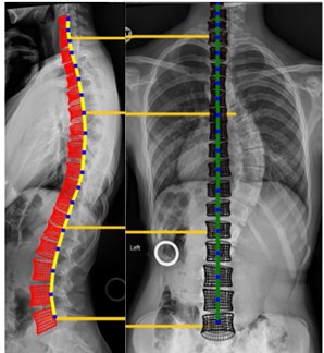
a)
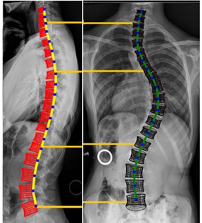
b)
The next step is to calculate the dynamic coefficient in analyzing the dynamic effects on the spine. Dynamic effects were measured by the person who jumped and dropped to the heel. We tried to use different types of shoes. Because the type of jumping that we thought was likely to occur mainly during sports activities, jumping was used with sports shoes instead of regular hard shoes. Otherwise, the effects of hard shoes would be even higher. This measurement will show how the quality of shoes will change the dynamic stress in the spine.
At the end of the article, the software's ability to change curvature and spine geometry is utilized. We will perform a stress analysis of two sitting positions in the car with three pathological curvatures.
2. FEM model description
The model contains five lumbar vertebrae and twelve thoracic vertebrae. There are sixteen intervertebral discs between them and one at the base of the spine model where it is fixed. The vertebrae are connected by the intervertebral discs, processus, muscles, and ligaments. In Fig. 2 the finite element model of vertebra and intervertebral disc is shown. Material properties of components of the spine were taken from [1-5, 8]. The geometry of vertebrae is based on the anatomical study of 3D geometry of lumbar and thoracic vertebra done in [6, 8-10]. Compared to [11], we have significantly transformed the FEM model so that we can refine the FEM mesh anywhere. The new components were added to the model-ligaments and cartilaginous endplate. These components have proved to be important in shock absorption and stabilizing the spine. Much work has been done by considering fluid elements in the nucleus pulposus parts of the spine. The more precise shape of vertebra was created due to anatomical attributes. This refinement of model allows us to analyze the relationship between the intervertebral disc and vertebra, which can be used, for example, in the design of artificial disc replacements.
Fig. 2Finite element model of: a) vertebra with precessus, muscles and ligaments, b) intervertebral disc
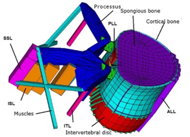
a)
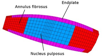
b)
3. Geometry variation - static solution
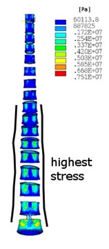
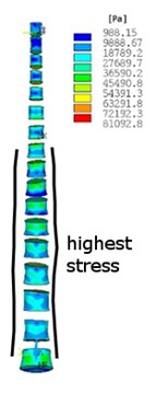
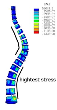
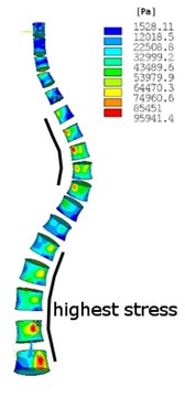
Structural analysis with a dead weight has been performed assumed upper part of body-head, neck, arms and a half part of the trunk. In Fig. 3, the equivalent von Misses stress is shown in two types of spine after the dead weight of the upper part of the body is applied as a loading. Vertebra bodies are chosen for better presentation of highest stress in the spine. In Fig. 3(a) and Fig. 3(c) the stress in cortical bone is shown. In Fig. 3(b) and Fig. 3(d) the stress in cancellous bone is shown. This analysis shows how the stress distribution and values in the scoliotic spine have changed against the non-scoliotic spine. It is clear that in scoliotic spine the highest stresses are more concentrated in internal arc of spine curvature and the values of stress increased. This analysis has found that by changing the curvature of the spine, the maximum stress will increase, and vertebra becomes more unevenly stressed.
Fig. 3Equivalent von Misses stress distribution in: a)-b) no scoliotic spine, a) cortical bone, b) cancellous bone, c)-d) scoliotic spine, c) cortical bone, d) cancellous bone
a)
b)
c)
d)
4. Measurement of dynamic effect
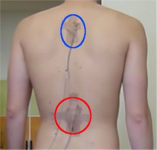
The measurements of dynamic effects on the spine were done using two accelerometers (Fig. 4) fixed near the upper lumbar and thoracic spine (Fig. 5).
Fig. 4Accelerometers
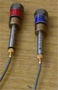
Fig. 5Accelerometers’ position on the back
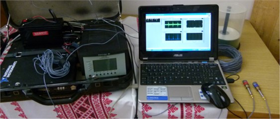
The acceleration of the jumps in straight position falling on heels (the worst case for the spine) were measured. The jumps were performed firstly in regular trainers, secondly in basketball trainers which should be adapted for the more extreme physical activity, so the effects should be dampened and not so harmful for the spine. The measurement was done using the apparatus shown on Fig. 6. The measured data were processed in LabView software.
Fig. 6Measuring apparatus
4.1. Measurements
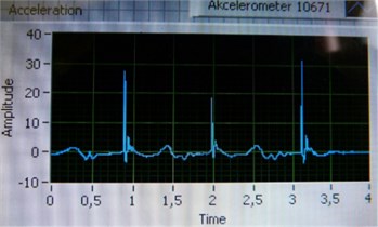
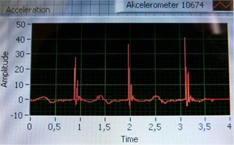
Three measurements for both trainers were performed. Three jumps were recorded during one measurement that lasted four seconds. The important outputs from one measurement were accelerations in thoracic and lumbar spine (Fig. 7).
The graphs from the listed measured values were done and peaks were recorded into Table 1 and Table 2.
Fig. 7Measurement output graph for: a) thoracic spine b) lumbar spine
a)
b)
Table 1Measured accelerations [m/s2] in regular trainers
Measurement No. | 1 | 2 | 3 | |||
Position on spine | ||||||
Jump No. | ||||||
1 | 29 | 32 | 31 | 19 | 41 | 48 |
2 | 30 | 36 | 12 | 19 | 27 | 39 |
3 | 27 | 39 | 31 | 36 | 33 | 32 |
Table 2Measured accelerations [m/s2] in basketball trainers
Measurement No. | 1 | 2 | 3 | |||
Position on spine | ||||||
Jump No. | ||||||
1 | 41 | 48 | 22 | 28 | 28 | 30 |
2 | 27 | 29 | 28 | 39 | 20 | 37 |
3 | 32 | 32 | 19 | 33 | 32 | 42 |
By averaging the results out, the acceleration in case of regular is 31.17 m/s2. For basketball trainers it is almost the same: 31.5 m/s2. The average acceleration of these values – 31.335 m/s2is taken to calculate the dynamic coefficient. For the precise results it is important to repeat exactly the same jumps, what proves to be impossible in reality. So, the results are influenced by the character of the jumps that may cause the results variations.
5. Dynamic amplification factor
The value of dynamic amplification factor (DAF) is obtained by division of the measured acceleration (31.335 m/s2) by the gravitational acceleration (9.81 m/s2), so we get DAF = 3.19.
6. Assessment of dynamic effect
Table 3Stresses after dynamic loading
Material | Max. stress [Mpa] | Dynamic coefficient | Stress after dynamic loading [Mpa] | Breakdown stress [3] [Mpa] | ||
Non-scoliotic spine | Scoliotic spine | No scoliotic spine | Scoliotic spine | |||
Cortical bone | 7.51 | 13.2 | 3.19 | 23.96 | 42.11 | 150 |
Cancellous bone | 0.081 | 0.096 | 0.26 | 0.31 | 2 | |
When the maximum stresses in scoliotic spine (the worst case) are multiplied by the dynamic coefficient, we will get the maximum stresses after dynamic loading. Comparing them with the breakdown stresses of particular materials respectively, there is still no danger of rupture.
7. Spine geometry in various seating position
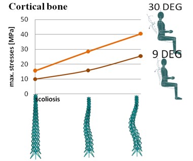
The analysis of different type of position in the car was done on our model. The software which was created allows to change the frontal and side geometry of the spine. In Fig. 8. the maximum values of equivalent von Misses stresses are compared. Two spine inclinations were analyzed with three different pathological curvatures of the spine.
Fig. 8Maximum stresses in spine with different configurations of geometry in cortical bone
8. Conclusions
The measurements of dynamic effect with two types of trainers has shown that average accelerations from measurements and jumps are almost the same. It is mainly caused by the fact that we cannot repeat the exactly the same jump. The second possibility is that the trainers have approximately the same properties. A suitable alternative for comparing the effect of the shoe on the stress in the spine would be to compare totally different types of shoe like trainers and high heels. The stress analysis has shown that after dynamic loading values of stress increased in both types of spine curvatures-scoliotic and non-scoliotic, but they are still in the limits of the failure of vertebra.
The analysis of a different sitting position has shown that with a higher inclination, the stress is much higher. The worst case has turned out to be a model with a 30 degree inclination and scoliosis in our test. An interesting test could be a dynamic effect test on a sitting person suffering from scoliosis, such as a car ride on a bumpy road.
References
-
Belytscho T., Kulak R. F., Schultz A. B. Finite element analysis of an intervertebral disc. Journal of Biomechanics, Vol. 7, 1974, p. 277-285.
-
Ben Hatira F., et al. A finite element modeling of the human lumbar unit including the spinal cord. Journal Biomedical Science and Engineering, Vol. 5, 2012, p. 146-152.
-
Brinckmann P., Frobin W., Leivseth G., Drerup B. Orthopädische Biomechanik, Wissenschaftliche Schriften. WWU Münster, 2012, (in German).
-
Deluca J. F., et al. Human cartilage endplate permeability varies with degeneration and intervertebral disc site. Journal of Biomechanics, Vol. 49, 2016, p. 550-557.
-
Divya V., Anburajan M. Finite element analysis of human lumbar spine. 3rd International Conference on Electronics Computer Technology, 2011.
-
Houwen et al. Geometry of the intervertebral volume and vertebral endplates of the human spine. Annals of Biomedical Engineering, Vol. 38, Issue 1, 2010, p. 33-40.
-
Kurutz M. Finite Element Modelling of Human Spine. Finite Element Analysis, IntechOpen, 2010.
-
Panjabi M. M., Goel V., Oxland T., Takata K., Duranceau J., Krag M., Price M. Human lumbar vertebrae – quantitative three-dimensional anatomy. Spine, Vol. 17, Issue 3, 1992, p. 299-306.
-
Panjabi M. M., Oxland T., Takata K., Goel V., Duranceau J., Krag M. Articular facets of the human spine – quantitative three-dimensional anatomy. Spine, Vol. 18, Issue 10, 1993, p. 1298-1310.
-
Panjabi M. M., Takata K., Goel V., Federico D., Oxland T., Duranceau J., Krag M. Thoracic human vertebrae – quantitative three-dimensional anatomy. Spine, Vol. 16, Issue 8, 1991, p. 888-901.
-
Sokol et al. M. Three-dimensional mechanical model of human spine and its versatility of use. Slovak Journal of Civil Engineering, Vol. 22, Issue 1, 2014, p. 37-42.
About this article

