Abstract
Measurement of the piston group behavior is still a challenge. Achieved accuracy and complexity go hand in hand with the financial requirements. This paper presents an unconventional measurement of the piston secondary motion using laser displacement sensors. Two sensors help capture the piston tilt angle, while the third sensor is used for the piston lateral motion measurement. These sensors are aimed at the piston crown. The passage between the laser source and the target spot has to be transparent. Therefore, side-valve internal combustion engine is employed. It enables the cylinder head to be made of the transparent material such as cast plexiglass. In the initial stage, the experimental engine is motored during the measurement. As for the measurement of the piston tilt angle, the results are within the physical limits. However, the same does not apply for the piston lateral results, where the measured values are too high, so the piston would penetrate the liner.
1. Introduction
Most of the vehicle manufacturers have to comply with both national and international laws influencing the design of their products. Traffic noise is classified as the one of the most environmental problems in the European Union. Therefore, regulations and test methods for measuring of noise emissions have been introduced so that environmental protection may be improved.
The powertrain is the primary source of vehicle internal noise and vibration. Internal Combustion Engine (ICE) consists of the piston group, which can be the cause of excess vibrations, especially when the piston slap motion occurs. The piston design has to be optimized in order to reduce these negative effects. For such purposes, the computational modelling, mainly based on Multi Body System (MBS) [1], is used the most. However, computational models are based on assumptions and mathematical models and therefore have to be validated experimentally. That is one of the reasons why experimental methods are still inevitable in the development process.
2. State-of-the-art
Until now, a whole variety of different experimental methods for the piston dynamics behavior has been developed. Instantaneous Indicated Mean Effective Pressure (IMEP) method [2-5] is based on the static equilibrium of the loads acting on the piston group. The piston group friction force is estimated by the vector addition of forces in the crank-train mechanism. That is the bottleneck of this method. The friction force is very small compared to the other loads, so it is extremely sensible to the measurement errors.
Another approach for the measurement of the friction force of the piston group is by the Floating Liner Engine (FLE) [6-8]. As the name gives a hint, the piston group friction force is measured by the reaction in the liner mounts in the axial direction. The biggest issues of this method can be contributed to the sealing of the combustion chamber and its affect to the measured reaction, the elimination of the cylinder head and the liner deformation. This method requires use of special single-cylinder engine.
The piston position can be measured by the eddy-current sensors [6], [9-11] which measure the piston-liner gap. The sensors are mounted on the piston skirt. If the sensors are supplied by the wire, the additional linkage mechanism is required in order to eliminate the fatigue wear of the wires. In the post-processing phase, the piston and the liner original shape has to be filtered. This method is based on the simple idea of measuring the distance between two bodies, but the conditions in the ICE complicate the measurement significantly.
There are many sources of the vibrations in the ICE. For instance, it is the pressure variations in the combustion chamber, the fuel or the air flow, the valve-train, the turbocharger rotor unbalance, the piston secondary motion and others. All these contribute to the overall engine vibrations. If the piston secondary motion is to be studied, it is essential to identify it. For such reasons, the measurement of other contributors has to be done. Afterwards, signal processing methods such as Wigner-Ville analysis [12], Wiener filter [13, 14], Blind Component Separation [15] and Blind Source Separation [16, 17] can be used.
3. Measurement
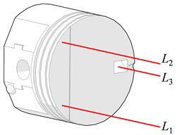
To estimate the piston secondary motion, the laser displacement sensors are aimed at three spots on the piston crown as depicted in Fig. 1. Such layout results in unique plane position of the piston.
Fig. 1Piston laser beam spots
This method is presented in [18], where it is applied on the motored motorcycle engine. The engine is installed without the cylinder head – the pressure in the combustion chamber is ambient. The laser displacement sensors are not mounted on the measured engine. This configuration may be an advantage and disadvantage at the same time. The measured quantity is the distance between the sensor and the beam spot on the piston crown. So, no additional filtering of the piston and the liner original shape is required. On the other hand, if the engine block is vibrating relative to the sensor, it is reflected in the measured signal as the piston secondary motion.
Another disadvantage is that the space between the beam source and beam target has to be transparent. Therefore, it is not possible to use ICE with Over Head Camshaft (OHC) or Over Head Valve (OHV) valve-train, due to the design of the cylinder head.
3.1. Test rig
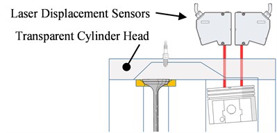
The SideValve (SV) engine (namely Briggs & Stratton Series 500, Table 1.) is employed for application of the above discussed technique of measuring the piston secondary motion by the laser displacement sensors. This engine has a simple cylinder head design without any valves, valve guides, rocker arms or camshaft, which is the case of OHC and OHV. Cylinder head of SV engine made of transparent material (plexiglass or polycarbonate) enables measurement of the piston loaded by the pressure in the combustion chamber, see the scheme in Fig. 2. Therefore, the Original Equipment Manufacturer (OEM) cylinder head is replaced with the one made of cast plexiglass.
Table 1Parameters of experimental SV engine
Rated power | N/A |
Torque | 6 Nm |
Displacement | 158 cm3 |
No. of cylinders | 1 |
Valvetrain | SV |
Bore | 65.1 mm |
Stroke | 47.7 mm |
Fig. 2Scheme of the measurement technique with SV engine and transparent cylinder head
Before the experiment started, it was unclear whether the laser beams were able to travel through the combustion gases unaffected, or not. In addition, the combustion process would cause additional vibrations of the engine block resulting in decreased accuracy. Therefore, the experimental SV engine was in the motored state during the measurement.
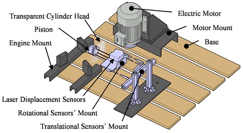
Fig. 3. shows the scheme of the test rig assembly. The electric motor drives the SV engine via the belt. Each part has its own bracket fixed to the ground. Three laser displacement sensors are mounted on the aluminum bracket that is connected to the head with spherical and translational joints, so the lasers position in all 6 Degrees of Freedom (DOF) are adjustable.
Fig. 3Scheme of the test rig assembly
3.2. Data handling
Laser displacement sensors a are aimed at the piston crown surface and sensor is aimed at the surface of 45° slope, as shown in Fig. 1. Piston tilt angle can be calculated from the measured values as:
where the superscript A stands for the actual value and the superscript 0 stands for the referential value of the displacement at the beginning of the measurement (TDC) and s is the displacement between the sensors and . The piston lateral motion can be estimated as:
where and are the laser beam lengths due to the rotation of the piston by the angle .
4. Results
One measurement contains 100 working cycles. The average of all correctly measured working cycles is made for further data handling. In case a defective working cycle was identified, it was excluded from the measured data.
The end of the compression stroke is defined in the 360° crank angle. The measured piston secondary motion is displayed in Fig. 4. The thick curve stands for the average values, while the thin curves stand for 68 percent probability of measuring the value (with the assumption of normal distribution). It is evident that the sample standard deviation is considerable higher at the moments around BDC at the end of the expansion stroke. This may be attributed to the temporary sensors cutoff in these intervals.
Fig. 4Measured piston: a) lateral motion, b) tilt angle for 1,000 rpm
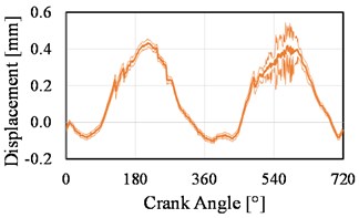
a)
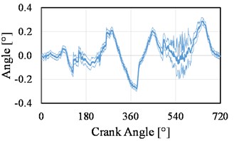
b)
The measured piston tilt angles lay within the reasonable values which are defined by the geometry of the piston and the liner. That is not true for the piston lateral displacements. The nominal radial clearance between the piston and the liner is equal to 0.053 mm. The amplitude of the piston lateral displacement is 0.267 mm. In other words, the measured piston lateral motion is degraded by a specific effect. The following causes were investigated:
• Large deformation of the piston and the liner;
• Corruption of the laser beam due to the transparent cylinder head interface;
• Vibrations of the engine.
None of the above possible reasons was confirmed to be the cause of unrealistic piston lateral motion measurement. Further investigation in this area is required.
4.1. Measurement repeatability
During the measurement process, the engine and the laser positions were modified along with the surrounding conditions (humidity, air temperature, etc.). Therefore, the measurement repeatability analysis is conducted. It assesses the impact of the random conditions on the results. As it was discussed in the previous section, the measured piston lateral motion is corrupted, so the measurement repeatability is undertaken on the piston tilt angle only.
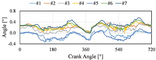
Seven measurements were carried out, and the laser sensors were repositioned slightly after each measurement session. The measurement results are illustrated in Fig. 5. Curves #1 through #7 are shifted by a certain tilt angle value due to the initial misalignment of the laser sensors.
Fig. 5Measurements of the piston tilt angle for different laser sensor locations
Afterwards, the measurement repeatability is evaluated using a Spearman’s rank correlation coefficient. The coefficient measures relationship between two variables. The closer the rank is to the value +1, the higher the correlation is.
Spearman’s rank correlation matrix for SV engine with 1,200 rpm is shown in Table 2. It is clear that most of the pairs are strongly and very strongly correlated. Lower ranks are in the pairs comprising measurement #7. This very measurement was conducted on the engine which was warmer than in the other cases. Therefore, the measurement #7 resulted in higher amplitudes of the piston tilt angle.
Table 2Correlation matrix
Measurement | #1 | #2 | #3 | #4 | #5 | #6 | #7 |
#1 | 1 | 0.83 | 0.84 | 0.76 | 0.80 | 0.73 | 0.61 |
#2 | 0.83 | 1 | 0.85 | 0.75 | 0.71 | 0.71 | 0.58 |
#3 | 0.84 | 0.85 | 1 | 0.75 | 0.81 | 0.74 | 0.58 |
#4 | 0.76 | 0.75 | 0.75 | 1 | 0.87 | 0.83 | 0.81 |
#5 | 0.80 | 0.71 | 0.81 | 0.87 | 1 | 0.85 | 0.64 |
#6 | 0.73 | 0.71 | 0.74 | 0.93 | 0.85 | 1 | 0.87 |
#7 | 0.61 | 0.58 | 0.58 | 0.81 | 0.64 | 0.87 | 1 |
5. Conclusions
Presented technique for the piston secondary motion measurement by the laser displacement sensors has lower cost requirements than other methods such as IMEP, FLE etc. In order to load the piston by the pressure in the combustion chamber, the SV engine with transparent cylinder head was used.
The measured piston tilt angles are classified as reasonable values. Unfortunately, there were moments during the measurement when the measured values of the piston tilt angle were suspected to be too much alike the piston primary motion. In addition, the temporary collapse of the laser displacement sensors signal did occur when the piston was located in the BDC. The measurement repeatability of the measurement is great.
On the other hand, the measured piston lateral motion is not trustworthy. Such lateral motion would lead to the piston-liner penetration. The impact of the deformation, the corruption of the laser beam and the engine vibrations were tested. But none of these aspects were confirmed to be the main reason of unrealistic results of the piston lateral motion and further investigation is needed.
References
-
Novotný P., Prokop A., Zubík M., Řehák K. Investigating the influence of computational model complexity on noise and vibration modeling of powertrain. Journal of Vibroengineering, Vol. 18, Issue 1, 2016, p. 378-393.
-
Uras H., Patterson D. Measurement of piston and ring assembly friction instantaneous IMEP method. SAE Technical Paper 830416, 1983.
-
Uras H., Patterson D. Effect of some lubricant and engine variables on instantaneous piston and ring assembly friction. SAE Technical Paper 840178, 1984.
-
Sethu C., Leustek M., Bohac S., Filipi Z., et al. An investigation in measuring crank angle resolved in-cylinder engine friction using instantaneous IMEP method. SAE Technical Paper 2007-01-3989, 2007.
-
Goto T., Aoyama S., Nagumo S., Nakajima Y., et al. Measurement of piston and piston ring assembly friction force. SAE Technical Paper 851671, 1985.
-
Ragot P., Rebbert M. Investigations of crank offset and it’s influence on piston and piston ring friction behavior based on simulation and testing. SAE Technical Paper 2007-01-1248, 2007.
-
Furuhama S., Takiguchi M. Measurement of piston frictional force in actual operating diesel engine. SAE Technical Paper 790855, 1979.
-
Yoshida K., Kusama K., Mizuma Y. Measurement of piston friction force on firing conditions. SAE Technical Paper 871219, 1987.
-
Offner G., Herbst H., Priebsch H. A methodology to simulate piston secondary movement under lubricated contact conditions. SAE Technical Paper 2001-01-0565, 2001.
-
Maassen F., Koch F., Schwaderlapp M., Ortjohann T., et al. Analytical and empirical methods for optimization of cylinder liner bore distortion. SAE Technical Paper 2001-01-0569, 2001.
-
Bird L., Gartside R. Measurement of bore distortion in firing engine. SAE Technical Paper 2002-01-0485, 2002.
-
Chiollaz M., Favre B. Engine noise characterisation with Wigner-Ville time-frequency analysis. Mechanical Systems and Signal Processing, Vol. 7, Issue 5, 1993, p. 375-400.
-
Pruvost L., Leclere Q., Parizet E. Diesel engine combustion and mechanical noise separation using an improved spectrofilter. Mechanical Systems and Signal Processing, Vol. 23, 2009, p. 2072-2087.
-
Badaoui M. E., Daniere J., Guillet F., Serviere C. Separation of combustion noise and piston-slap in diesel engine – Part I: Separation of combustion noise and piston-slap in diesel engine by cyclic Wiener filtering. Mechanical Systems and Signal Processing, Vol. 19, 2005, p. 1209-1217.
-
Antoni J. Blind separation of vibration components: principles and demonstrations. Mechanical Systems and Signal Processing, Vol. 19, 2005, p. 1166-1180.
-
Liu X., Randall R. B. Blind source separation of internal combustion engine piston slap from other measured vibration signals. Mechanical Systems and Signal Processing, Vol. 19, 2005, p. 1196-1208.
-
Serviere C., Lacoume J. L., Badaoui M. E. Separation of combustion noise and piston-slap in diesel – Part II: Separation of combustion noise and piston-slap using blind source separation methods. Mechanical Systems and signal Processing, Vol. 19, 2005, p. 1218-1229.
-
Tan Y. C., Ripin Z. M. Technique of measuring piston secondary motion using laser displacement sensors. Experimental Mechanics, Vol. 52, 2012, p. 1447-1459.
About this article

The research leading to these results has received funding from the Project FSI-S-17-4104 granted by Specific University Research of Brno University of Technology and the Project FV 17-34, Fund of Science FME 2017. The authors gratefully acknowledge this support.
