Abstract
Aiming at the difficulties in realizing the accurate control due to the nonlinearity of the automatic drilling system of oil drilling rig, a design scheme is proposed by giving a constant drilled-pressure to the rig for fuzzy control. Sampling error with changes in the signal was sent into the fuzzy controller, which turned the signal into a fuzzy volume. Subsequently, a precise volume was obtained accordingly and then added to an actuator for the motor control. According to the MATLAB simulation results, the response could be faster and more stable compared with the traditional control.
1. Introduction
When the drill string is drilling downward, friction comes along. In the early stage, the drilling system was controlled by manual feeding with a simple structure. An inevitable problem was the difficulties in realizing precise control of nonlinear WOB, which was also complicated by a high drilling intensity. With the development of the automatic feed technology under constant drilling pressure, pleasant progresses have been made in the drilling speed, smoothness and drilling quality.
At present, an automatic drilling system under constant drilling pressure mainly involves the use of the PlD control technology [1-3]. During the drilling process, however, the drilling pressure is influenced by the geologic structure, including such characteristics as multi-variable, strong coupling and nonlinearity [4, 5]. It is not as easy as it looks to establish the time-delay, time-varying and non-linear mathematical models. Therefore, even if the closed-loop control features certain accuracy, stability and fastness, this conventional control method cannot effectively overcome the large-scale variation of load parameters and the nonlinear effects, being unable to achieve more accurate and stable control [6-8].
In this paper, the constant-weight-pressure automatic drilling control system was investigated with the drilling rig based on fuzzy control. According to the characteristics of the pressure variation, a fuzzy controller was designed and simulated experimentally. It has been verified that the WOB control system with a reasonable structure, strong adaptability and stable drilling response, being able to improve the control performance of the system [9].
The design method of control algorithm and system model based on the starting point and the performance index is different, easily lead to large differences; but a system language control rule has relative independence, using these fuzzy control rules between the connection, easy to find compromise choice, the control effect is better than the conventional controller. The robustness of fuzzy control system is strong, and the influence of disturbance and parameter change on control effect is greatly weakened, especially for nonlinear, time-varying and pure time-delay systems.
2. Structure design of control system
The so-called automatic drilling refers to that the driller, in the normal drilling process, does not rely on the personnel regulation, but follow the drilling process requirements, where the control system is counted on automatically adjusting the pressure and speed, while feeding into the drill. The working process is as follows: The control system automatically detects the WOB and then compares it with the given WOB value. If there is any deviation, the control algorithm works for calculation, and then a brake signal (0-20 mA current signal) is given to the hydraulic disc brake mechanism, which produces a certain braking force. Consequently, the drill tool begins to change the speed. As the final speed gets stable, the drill WOB will reach the set point.
To improve the control precision, the whole control system may be taken as a three-ring control system. The system block diagram is shown in Fig. 1.
Fig. 1Block diagram of automatic feed control system
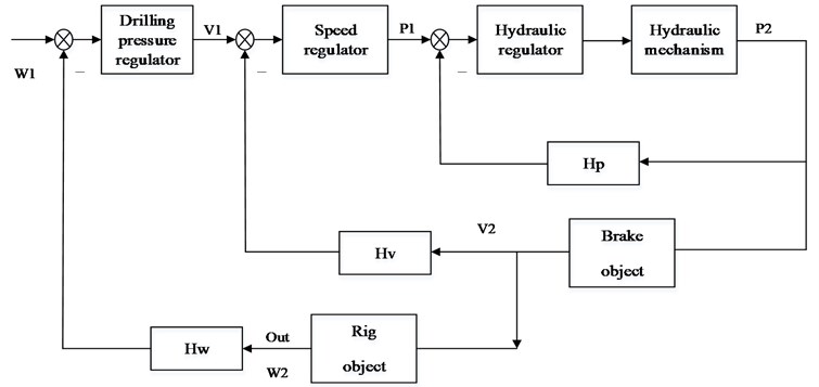
Here, the outer ring is the WOB adjustment section, where the WOB regulator used a given W1 and the deviation of WOB bit W2 for the calculation of a speed of a set point v1: the speed set point v1 was sent into the central ring, which acted as the speed adjustment part. After the operation of the deviation of V1 and the actual speed V2, a pressure given P1 of the hydraulic system was output. The central ring ensured that the output speed V2 was same as the given speed V1. Hydraulic set point P1 was sent into the inner ring, which acted as the hydraulic pressure regulating portion, ensuring that the actual pressure P2 output by the hydraulic mechanism was the same as the given pressure P1. So, in the case of a given speed v1, the output weight w2 would be the same as the given WOB w1, so as to achieve the purpose of constant WOB control [1].
3. Design of control algorithm
3.1. Control of hydraulic inner ring
According to the principle for hydraulic disc brake control, it is easy to get the block diagram of the pressure control loop of the hydraulic system, as shown in Fig. 2.
Fig. 2Schematic diagram of hydraulic inner ring control
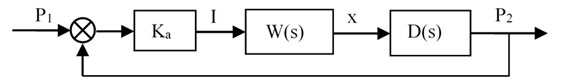
where, is the given pressure target value, is the pressure difference amplification factor, is the input of the electro-hydraulic servo valve, is the transfer function of the electro-hydraulic servo valve, is the main spool displacement, is the transfer function from the spool displacement to the cylinder output pressure , i.e., the mathematical model of the hydraulic mechanism.
Through the query parameters and calculation, we finally get:
Among them, all parameters of , and are obtained through experimental data.
3.2. Internal loop control strategy
As shown in Fig. 3, is a proportional-integral controller and is a derivative controller. Here we introduced the integral to eliminate the steady-state error of the system with an increased overshoot value. To offset the overshoot caused by the integration, differential was introduced. Additionally, the dynamic process and faster response of the system requires shorter adjustment time at a proper ratio. The unstable inner loop may cause the entire system to oscillate frequently. Measures should be taken to implement the idea of series-parallel differential correction + negative feedback control strategy: the system’s negative feedback subject to the change trend of input pressure shall be adapted for better dynamic performance. In this way, oscillation and overshoot became much lower and correspondingly, more stable and robust. The derivative pre-PID control system had a structure as shown in Fig. 3.
3.3. WOB Control of outer ring
The fuzzy control is adopted for the WOB control of outer ring.
The control system works with the “double-in-single-out” fuzzy controller [2]. The input value is the deviation between the WOB reference value and the measured value, and the deviation rate of change ; the output value is the input control voltage of the inverter. Fig. 4 is a block diagram of the fuzzy control system [3]. The control process is to compare the controller timing sampling WOB value and the value of change therein and the set point. The obtained value of WOB deviation e and the rate of change are taken as an input variable of PLC controller, and via the fuzzy controller, output frequency of control inverter n is obtained.
Fig. 4Block diagram of the fuzzy control system
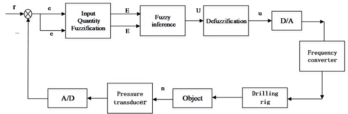
– given bit value; – deviation signal; – rate of change; – inverter control signal; – output frequency of frequency converter
3.3.1. Input blurring
In the fuzzy controller design, let have the set of words [NL, NM, NS, Z0, PS, PM, PL] [4], the domain is [, –3, –2, –1,0, +1, +2, +3,]; has the set of words [NL, NM, NS, 0, PS, PM, PL], the domain is [, –3, –2, –1,0, +1, +2, +3 ,,]; has the set of [NL, NM, NS, Z0, PS, PM, PL], the domain is [, –3, –2, –1,0, +1, +2, +3,]. Let , , and N0 represents an expected value. Then, , and are fuzzified, the fuzzy quantization tables of variables and are obtained according to the experience of pH control.
3.3.2. Fuzzy decision and fuzzy control rules
The experience in the control of the value of WOB is summarized to obtain the control rules, as shown in Table 1. The principle of selecting the control variable is: when the error is large or larger, the control quantity is selected to eliminate the error. When the error is small, attention should be paid to prevent overshoot in the choice of control, subject to the stability of the system. A total of 49 rules.
Table 1Control rules
NL | NM | NS | ZO | PS | PM | PL | ||
NL | NL | NL | NL | NL | ZO | ZO | ZO | |
NM | NL | NL | NM | NM | PS | PS | PS | |
NS | NL | NL | NM | NS | PS | PM | PM | |
ZO | NL | NM | NS | ZO | PS | PM | PL | |
PS | NM | NM | NS | PS | PM | PL | PL | |
PM | NS | NS | NS | PM | PM | PL | PL | |
PL | ZO | ZO | ZO | PL | PL | PL | PL | |
4. The stability of the fuzzy controller
Lemma 1. The following inequalities exist in every GFP subspace :
Prove.
It is known from property 1 that most 2 rules are activated in every GFP subspace, so there are:
Theorem 1.
Fuzzy system in sufficient conditions for equilibrium is globally asymptotically stable in the memory in and , the 0 meet > 0:
Prove.
First, the following continuous piecewise smooth Lyapunov functions are constructed:
It is directly obtained from the upper form. For any = 0, Lyapunov function constructed with 0. The Lyapunov function of the above structure is continuous at the boundary of the adjacent GFP subspace, and the derivatives at the boundary are taken as the left and right partial derivatives respectively:
By Eqs. (1)-(5) available:
Therefore, the fuzzy control system is asymptotically stable at the equilibrium point 0.
5. Software design
During the control, the WOB signal acted on the tension sensor, and was judged by the selection unit after A/D conversion. In the normal range, the sampling value of the WOB signal was compared with the given WOB value. After the fuzzy control operation, the generated signal was taken as the reference value of the speed controller. The speed-encoded signal mounted on the winch was sent to the computer and compared with the reference signal produced by the WOB control. After the speed control operation, the control signal was moved to the hydraulic controller, and compared with the output pressure of the hydraulic controller. The results of the operation through D/A conversion were transmitted into the frequency control unit, from which the voltage signal of variable frequency was output to control the motor speed of the winch for automatically drilling. Motor speed may change via the speed reducer and winch drum and other transmission devices, and ultimately control the speed of the hook down to complete the closed-loop control on a constant pressure.
6. Simulation
SIMULINK toolbox simulation was applied to observe the influence of the fuzzy control system on the input step signal.
6.1. Hydraulic simulation of inner ring
Inner ring hydraulic control simulation structure is shown in Fig. 5. The simulation results are shown in Fig. 6.
6.2. WOB simulation of outer ring
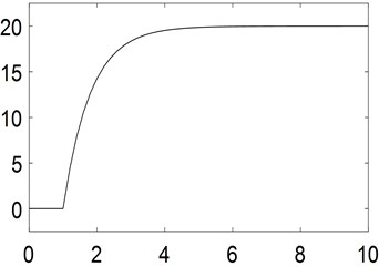
WOB Simulation of outer ring is shown in Fig. 7. The simulation results are shown in Fig. 8. In Fig. 7, fuzzy control is added. As can be seen from Fig. 8, we can see that the dynamic performance of the system is significantly better than that of Fig. 6. The main reason is that we applied the fuzzy control rule of 7*7. By comparing the simulation curves, we can clearly see that the effect of Fig. 8 is better than that of Fig. 6.
Fig. 5IRH control-simulation structure
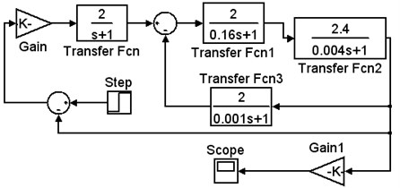
Fig. 6IRH control-simulation results
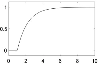
Fig. 7WOB control of outer ring-structure
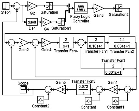
Fig. 8WOB control of outer ring-results
7. Conclusions
In this paper, a fuzzy control system based on PLC is designed for automatic feed drilling operation of oil rig. The innovation of the system is highlighted in the combination of the highly reliable PLC and the advanced fuzzy control technology. This new system is available to provide reasonable control schemes, high steady-state precision and small overshoot. As a strong addition, it has a simple structure highlighted in impressive convenient debugging, anti-interference and robustness.
References
-
Gao Yan Intelligent Control System for Automatic Drilling of Oil Rig. Xi’an University of Architecture and Technology, 2014.
-
Tanaka K., Wang H. O. Fuzzy control systems design and analysis. Automatica, Vol. 39, Issue 11, 2014, p. 2011-2013.
-
Shah M. H. M., Rahmat M. F., Danapalasingam K. A., et al. PLC based adaptive fuzzy PID speed control of DC belt conveyor system. International Journal on Smart Sensing and Intelligent Systems, Vol. 6, Issue 3, 2013, p. 1133.
-
Wu J., Zhao Y. Q., Ji X. W., et al. A modified structure internal model robust control method for the integration of active front steering and direct yaw moment control. Science China Technological Sciences, Vol. 58, Issue 1, 2015, p. 75-85.
-
Danilov B. B., Smolyanitsky B. N. Determination of length of horizontal pneumatic transport line in drilling machine for mud removal by negative pressure. Journal of Mining Science, Vol. 52, Issue 4, 2016, p. 698-703.
-
Esim E., Şahin Yıldırım Drilling performance analysis of drill column machine using proposed neural networks. Neural Computing and Applications, 2016, p. 1-12.
-
Tait R. D., Maxon C. L., Parr T. D., et al. Benthos response following petroleum exploration in the southern Caspian Sea: Relating effects of nonaqueous drilling fluid, water depth, and dissolved oxygen. Marine Pollution Bulletin, Vol. 110, Issue 1, 2016, p. 520-527.
-
Oezkaya E., Beer N., Biermann D. Experimental studies and CFD simulation of the internal cooling conditions when drilling Inconel 718. International Journal of Machine Tools and Manufacture, Vol. 108, 2016, p. 52-65.
-
Kazemi M. V., Moradi M., Kazemi R. V. Fuzzy logic control to improve the performance of the direct power control based DFIG. Compel International Journal for Computation and Mathematics in Electrical and Electronic Engineering, Vol. 33, Issue 1, 2014, p. 254-272.
About this article

Research Foundation of Chongqing Education Committee (Grand Nos. KJ1501325, KJ1601303 and KJ1401302). Natural Science Foundation of Chongqing (Grand No. cstc2014jcyjA70001). Research Foundation of Chongqing University of Science and Technology (Grand No. ck2017zkzd006).
