Abstract
With the continuous popularization and application of TBM equipment and technology in the field of coal mine, aiming at the problems of small torque and small propulsion of existing TBM advanced exploration drilling rigs for coal mine, which is difficult to drill long borehole, and lack of special high-power drilling equipment to match with it, a high-power drilling rig for coal mine TBM is developed. This paper introduces the structure of the drilling rig, analyzes the structure and principle of the luffing mechanism and the rotary table protection device, also the strength of the key parts. Through the application in Guineng Group Heilaga Juxin coal mine shows that this equipment has large torque and propulsion, the hydraulic system and operation mode meet the requirements of long-distance separate layout in TBM. The drilling rig has good stability and high efficiency, and can meet the various needs of long drilling for advanced exploration, which promotes the application of TBM equipment and technology in the field of coal mine.
1. Introduction
In recent years, the drivage efficiency of rock roadways has become an important factor restricting the high-efficiency and high-quality development of the coal industry. At present, cantilever road headers are used widely in China with traditional methods that drilling and blasting. There are so many technical problems such as low efficiency, imbalance in coal mining and tunneling, and poor safety. Compared with traditional methods, TBM technology can realize continuous rock breaking, rock loading, reloading, support, spray dust prevention and other processes. It has a high degree of mechanization, simple process, fast construction speed, high construction quality, simple support, and work security and other advantages [1-3].
Usually, before using TBM to the construction of mines, tunnels and urban underground pipe corridors, a comprehensive geological survey and exploration will be carried out. Accurate geological conditions can be reported through a variety of technologies and methods. During the construction, most of the advanced explorations are using geophysical methods, although equipped with advanced exploration drilling rigs, the frequency of use is relatively low. However, the tunneling construction in coal mines has such problems as large construction depth, complicated geological conditions, and the difficult to accurately predict the exploration in the early stage. For these reasons, Chinese government has made a mandatory requirement of "exploration at every excavation, first exploration and then excavation". At present, the advanced exploration rig equipped with TBM generally adopts the impact-rotary, the torque and thrust are relatively small (torque no more than 1000 Nm, thrust is about 5-20 kN), and the depth of drilling generally no more than 30 m. Frequent drilling and tunneling alternation has a great impact on the tunneling efficiency. In addition, the diameter of the drill holes are generally small, and the accuracy of drilling is poor, easy to be affected by the combination of propulsion force, rotation torque and shock wave. Inclination affects the accuracy of advanced exploration. These problems greatly restrict the popularization and application of TBM equipment in coal mines.
In response to the above problems, a high-power split-type remote-controlled drilling rig that can be integrated in a TBM with a diameter of between 3.5 and 6 m has been developed. The design capacity of drilling rig is 300 m, and the most type of TBM exploration drilling hole can be satisfied. Also, it can support with various construction techniques such as rotary drilling, pneumatic percussion drilling, and hydraulic percussion drilling [4-10].
2. Overall plan
Combining the characteristics of TBM's internal space structure and advanced exploration construction requirements, the drilling rig is designed with a split layout, consisting of a main unit, an operation station, and a pumping station, and each part is connected by high-pressure tubing. The whole machine adopts electro-hydraulic control hydraulic system, which is operated by remote control. The main unit and operation station are set in the trailer behind the TBM cutter head, and the pump station is arranged behind the main engine about 50 m. During drilling, the drill pipe can pass through the cutter head from the annular space between the shield and the propulsion mechanism, thereby realizing the advance exploration drilling construction around the front of the tunnel.
Fig. 1Drilling rig layout in TBM: 1 – cutter head; 2 – shield body; 3 – main unit; 4 – operation station; 5 – trailer; 6 – pump station
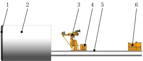
Table 1Main technical parameters
Items | Numerical value |
Maximum torque | 6500 Nm |
Maximum speed | 200 r/min |
Adjustment range of circumferential angle | 130°~+130° |
Adjustment range of spindle inclination angle | –40°~+40° |
Maximum working radius | 2260 mm |
Maximum feed force / pull-out force | 140/140 kN |
Remote control distance | 50 m |
Size of main unit | 3260×1500×3600 mm |
Size of operation station | 1100×900×1170 mm |
Size of pump station | 2100×2200×1500 mm |
3. Structure design of main engine
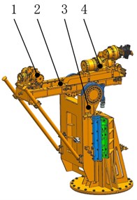
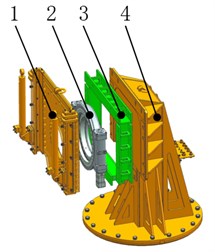
The main unit is mainly composed of a rotary head, a clamper, a propulsion device, a luffing mechanism, a base, and so on. The rotary head is equipped with a hydraulic chuck, which can clamp the drill pipe and provide drilling rotation power; the clamper is used to clamp the drill pipes in the hole, and cooperates with the rotary head to accomplish the screwing and unloading of the drill pipe thread; the cylinder of the propulsion device can drive the rotary head to reciprocate along the guide rail, which is provide the drilling pipe with propulsion force or pulling force; the luffing mechanism is used to adjust the circumferential angle, main shaft angle, working radius and other parameters to meet the requirements for drilling hole.
Fig. 2The structure of main unit: 1 – a clamper; 2 – a propulsion device; 3 – a luffing mechanism; 4 –rotary head
3.1. The design of the new luffing mechanism
In order to meet the needs of TBM advanced exploration for circumferential angle adjustment range, maximum working radius and spindle inclination angle adjustment range, a new luffing mechanism is designed, which is mainly composed of a base, a sliding saddle, swing drive to adjust circumferential angle, rack unit, swing drive to adjust inclination, hydraulic diagonal shore, etc.
The base is connected to the TBM platform. Sliding saddle and the base are connected by a circumferential angle swing drive. Sliding saddle can be rotated along the axis of the swing drive to adjust the circumferential angle; the rack unit is embedded in the slideway of the sliding saddle, and a cylinder connects them. the rack unit can slide to adjust the drilling radius under the drive of the oil cylinder. The propulsion device and the rack unit are connected by the inclination swing drive set on both sides, and the propulsion device can rotate along the axis of the swing drive to adjust the drilling. A set of hydraulic diagonal shore mechanism is also arranged between the rack unit and the luffing mechanism, which can reduce the vibration during the drilling process and improve the construction stability.
Fig. 3The gestures of drilling rig: a) circumferential adjustment; b) adjustment of main shaft angle
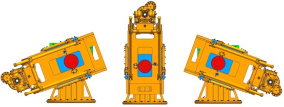
a)
b)
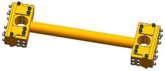
3.2. Hydraulic diagonal shore mechanism
Since the drilling rig is still some distance away from the hole, in order to reduce the shaking of the device during high-speed drilling, a set of hydraulic diagonal shore mechanism is designed between the rack unit and the propulsion device, which is mainly composed of diagonal poles and hydraulic chuck. One end of the diagonal poles is hinged with the rack unit, and the other end passes through the holes on both sides of the hydraulic chucks. The hydraulic chucks adopts the principle of hydraulic clamping and spring loosening. During the drilling process, the hydraulic chucks clamps the diagonal poles, and the propulsion device, the diagonal poles, and the rack unit form a triangular stable structure. When the hydraulic chucks is loosened, the diagonal poles can slide in the through hole to adjust the inclination radius.
Fig. 4The hydraulic chuck
3.3. Checking and protection of circumferential swing drive
Under extreme conditions, the maximum moment applied to the swing drive is the maximum working radius of the drilling rig, which is 2260 mm. After calculation, the capsizing moment of the swing drive reaches 316.4 kN. In order to ensure the safety of construction, in general, it is required that the maximum capsizing moment of the swing drive should not exceed 76 % of the maximum rating. The capsizing moment rating of the swing drive which is the largest model is only 388 kN. In order to improve the safety factor and meet the requirements, a support device is designed between the sliding saddle and the base to reduce the load of the swing drive.
Fig. 5Braced structures of circumferential swing drive: 1 – sliding saddle; 2 – circumferential swing drive; 3 – braced structures; 4 – base
3.4. Checking of sliding saddle
In addition to the circumferential swing drive, the strength of the sliding saddle also directly affects the reliability of the entire machine. The rail slide of rack unit is embedded and connected with the sliding saddle, and the reaction force of the feeding and pulling force under the extreme working condition will act on the sliding saddle through the rack unit. The finite element analysis of the force of the sliding saddle and the rack unit under the conditions of maximum conditions are carried out. Through simulation, on the basis that the structural strength meets the requirements, the lightweight optimization of the structure is completed.
After optimization, in the case of the maximum feed force, the maximum stress point appears in the upper center of the sliding saddle, reaching 180 MPa. In the case of the maximum pulling force, the maximum stress point appears in the slideways on both sides of the sliding saddle, reaching 160 MPa. Generally speaking, the structure meet the using requirements for this kind of material.
4. Design of hydraulic system
The drilling rig adopts a dual-pump open design. The main pump supplies rotation and quickly feed and pull-up, and the second pump supplies drilling and auxiliary functions. According to the internal space of the TBM, the power pump station of the drilling rig is arranged about 50 m behind the main engine. Because the distance is too far, the feedback signal of the pump has a large delay that lead to the action slowly. Therefore, we replace the conventional load sensing pump with a constant pressure variable pump for more suitable. Since the second pump pressure needs to be adjusted frequently, a constant pressure variable pump with remote control and pressure adjustment is selected, and the main pump adopts a constant pressure variable pump with pressure cut-off.
In order to solve the problem of the pressure oil in the pipeline returning to the hydraulic pump during the power-off process, which causes the pump to reverse and impact damage, a power-off protection hydraulic control circuit is designed. Before the power is cut off, the electromagnetic unloading valve can be opened in advance, and the hydraulic pump is transformed from a constant pressure state to a large flow unloading state, which reduces the pressure in the pipeline, thereby solving the above problems.
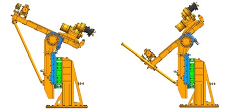
5. Application
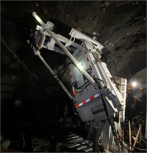
On March 15, 2021, the TBM named “China Railway No. 865” equipped with this advanced exploration drilling rig started successfully in Guizhou Guineng Group Heilaga Juxin Coal Mine. The diameter of the TBM is 6 m, and the total designed tunneling length is about 5.6 kilometers. The lithology is mainly sandstone and limestone, mixed with mudstone. The rock hardness is 40-60 MPa, and the maximum is 100 MPa. It traverses 8 coal seams with a buried depth of 500 m-900 m. As of April 8, the advanced exploration drilling rig has completed 4 advanced exploration drilling holes, with an average hole depth of 140 m, and a drilling efficiency of 35 m/h. The application marks the successful development of the first coal mine TBM equipped with a special high-power drill for advanced exploration drilling in China.
Fig. 6Construction state in coal mine
6. Conclusions
1) This high-power advanced exploration drilling rig for coal mining TBM, which is developed according to the compact space inside the TBM. The main machine and operation station is front-mounted, and the power pump station is rear-mounted. The torque capacity, feed and pull-out force are large, also the whole drilling rig with a good stability. It can meet the long boreholes construction needs of TBM advanced exploration in underground coal mines.
2) The drilling rig can be mounted on a TBM with a diameter between 3.5 m and 6 m. The luffing mechanism is designed for the characteristics of TBM's advanced exploration. The adjustment range of circumferential angle, spindle inclination, and working radius is large, which can meet the needs of various advanced exploration drilling arrangements.
3) The application in Guineng Group Heilaga Juxin Coal Mine shows that the hydraulic system and operation mode of the whole drilling rig meet the requirements of long-distance separation layout. The drilling ability is good, and good construction efficiency has been achieved. The development of this equipment promotes the application of TBM equipment and technology in the field of coal mine.
References
-
S. H. Yang, F. Rui, W. L. Jiang, and S. H. Zhang, “Development and application of full-section rock tunneling boring machine in coal mine,” (in Chinese), Coal Science and Technology, Vol. 47, No. 6, pp. 1–10, 2019, https://doi.org/10.13199/j.cnki.cst.2019.06.001
-
H. J. Tang., “Groundwater prevention and control for TBM construction method in coal mine inclined shaft,” (in Chinese), Coal Engineering, Vol. 48, pp. 37–38, 2016.
-
Y. C. Wang, L. G. Du, Y. C. Wang, and Y. L. Zhang, “Key technology of advance geological prediction and pretreatment of TBM construction in deep-buried tunnel,” (in Chinese), Tunnel Construction, Vol. 39, No. 8, pp. 1350–1356, 2019.
-
L. Nie et al., “TBM-mounted seismic ahead-prospecting for fast detecting anomalous geology ahead of tunnel face,” IEEE Access, Vol. 9, No. 99, pp. 359–369, 2021, https://doi.org/10.1109/access.2020.3045701
-
J. Park, K.-H. Lee, J. Park, H. Choi, and I.-M. Lee, “Predicting anomalous zone ahead of tunnel face utilizing electrical resistivity: I. Algorithm and measuring system development,” Tunnelling and Underground Space Technology, Vol. 60, pp. 141–150, Nov. 2016, https://doi.org/10.1016/j.tust.2016.08.007
-
S. Li et al., “An overview of ahead geological prospecting in tunneling,” Tunnelling Underground Space Technol, Vol. 63, pp. 69–94, Mar. 2017, https://doi.org/10.1016/i.tust.2016.12.011
-
Y. Zhao, H. Jiang, and X. Zhao, “Tunnel seismic tomography method for geological prediction and its application,” (in Chinese), Applied Geophysics, Vol. 3, No. 2, pp. 69–74, Jun. 2006, https://doi.org/10.1007/s11770-006-0010-7
-
A. Alimoradi, A. Moradzadeh, R. Naderi, M. Z. Salehi, and A. Etemadi, “Prediction of geological hazardous zones in front of a tunnel face using TSP-203 and artificial neural networks,” (in Chinese), Tunnelling Underground Space Technol, Vol. 23, No. 6, pp. 711–717, 2008, https://doi.org/10.1016/i.tust.2008.01.001
-
G. Q. Xue, Y. J. Yan, X. Li, and Q. Y. Di, “Transient electromagnetic S-inversion in tunnel prediction,” Geophysical Research Letters, Vol. 34, No. 18, pp. 1–5, 2007, https://doi.org/10.1029/2007gl031080
-
X. S. Zhou., “Techno-economic Comparative Analysis of TBM method and drilling and blasting method,” Xi’an University of Technology, Shaanxi, Xi’an, China, 2010.
-
S. Elyasi, “Developing an evaluation model for economic feasibility analysis of using mechanical boring machines (TBM vs Roadheader) in one of the largest coal reserves in Iran,” Mining, Metallurgy and Exploration, Vol. 38, No. 2, pp. 1081–1094, Apr. 2021, https://doi.org/10.1007/s42461-021-00391-1
Cited by
About this article

