Abstract
This work aims at the utilization of an orthotropic damper in demolition and forming machines. FEM model and quasi-dynamical calculations are used for the solution. After that the resulting force affecting the underlying bed is analysed. The research traces the dependence of the mass of orthotropic material on the time of force process. Based on the measured data it is possible to design a new orthotropic damper for the machines.
1. Introduction
This article deals with consequence of using orthotropic material in demolition and forming machines. For accurate substructure design it is necessary to protect a machine from substantial damage during a shock wave. Every demolition and forming machine is exposed to shock waves during their life cycle and these events strongly shorten their lifetime. EU standards take dynamic load factors into the static calculation, but there is no clear definition of how great peak force from the shock waves on the foundation is. It is necessary to know the peach force for an appropriate draft of a damper. We endeavour to prove a hypothesis that orthotropic material contributes to improving mechanical properties. For this purpose, we created an experiment calculated as a quasi-dynamical problem. We used a virtual model with a real mechanical attribute. The experiment is divided to three parts. All parts are solved with the same dynamical load but different mass of orthotropic material.
2. Experiments
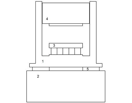
We compiled a virtual model of demolition assignment (Fig. 1). The frame (Fig. 1(1)) of this device was erected on a concrete foundation (Fig. 1(2)). In the middle of the frame an anvil (Fig. 1(3)) and its grip were situated. Steel hammer (Fig. 1(4)) was dropped on the anvil. The hammer was bounded to the frame by a slide-way. The body and anvil’s weight was 6,500 kg and they were made from regular constructional steel – S 355J2G3 [1]. The hammer is made from tenacious steel-Hardox HiTuf. The hammer weighed 6,000 kg. The concrete foundation weighed 8,500 kg and it was made from monolithic concrete – C40/50. The machine was damped by an orthotropic material (Fig. 1(5)) localized between the frame and the concrete foundation. In this case was northern red oak (Lat. Quercus rubra) chosen [2].
2.1. Load
All virtual models were loaded with the gravity acceleration that assumes an average value of 9.81 m·s-2. The acceleration was oriented opposite to orientation of the main axis . Before proper quasi-dynamical calculation, it was necessary to stabilize the model. This means to define contactable bodies and incorporate contact area of the bodies. In each of the three experiments, a load in the same configuration was applied. The shock wave originated in an impacting the hammer on the anvil from a 1,000 mm drop. During the experiments, the reaction force under the concrete foundation on the background was recorded.
Fig. 1A schema of the demolition equipment: 1 is the frame; 2 is the foundation; 3 is the anvil; 4 is the hammer; 5 is the orthotropic damper
2.2. Predicted behaviour
All virtual models behave according to below-mentioned derivative equations. From Newton’s Second Law Eq. (1) for object (a stationary part of machine) was acquired. It is written in shape :
where is force dependent on time. Eq. (1) is integrated within the boundaries (the moment immediately before the collision) and (the moment after the collision). The boundaries are determined by the interval during the collision. Eq. (2) is integrated for the modification of momentum object for :
For an algebraical expression, the right side of Eq. (2) is dependent on the time behaviour of the interactive force during the collision. The description of this event is given by I – Impulse of Force in Eq. (3) [3]:
2.3. Variants
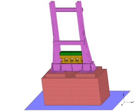
The first experiment was carried out as a reference sample. Therefore, the virtual model was drafted without a damper. The second experiment was prepared with a 150 mm layer of orthotropic material for the damping (Fig. 2). This thickness was recommended for a most common demolition and forming machines. The third virtual model was designed with a 1000 mm layer of orthotropic damper. This enormous mass of orthotropic material for the damping was crucial for accentuating the impact of the damper in the mechanical system. All virtual experiments were calculated in the MSC Marc software.
Fig. 2A FEM model of the second experiment-demolition equipment with a 150 mm layer of orthotropic material
3. Results
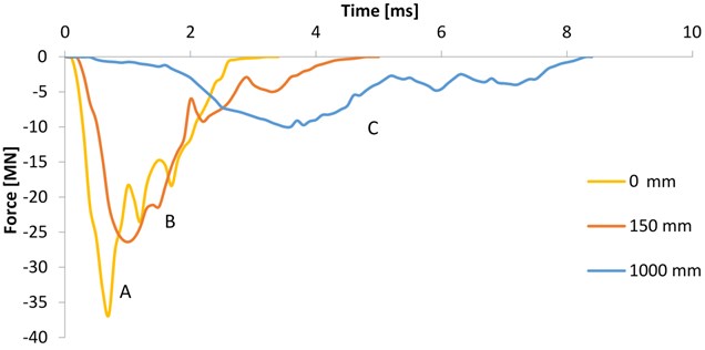
The value of the reaction force was measured under a concrete foundation and it was comparable with the force to the underlying bed. In the first experiment without the orthotropic damper there was an increase to 36.8×10⁶ N ≅ 36.8 MN (Fig. 3). The next peak force was at 24.3 MN. The last force peaked at 18.5 MN.
In the second experiment with a 150 mm orthotropic damper the force reached its maximum at 26.4 MN. Other peak forces were recorded for the magnitude of 9.2 MN and 5 MN. The force in the last experiment reached 10 MN. The next peak force was at 4.8 MN while the last peak was recorded for the magnitude of 4 MN.
Fig. 3A graph of the reaction forces which are measured under concrete foundation
4. Discussion
The first experiment (line A) without damper is carried out like a reference sample, for evaluation is used method described in this article [4]. The force achieves its maximum magnitude in its peak first. The curve indicates only very little damping compared to other curves. Therefore, the force gains such a high value in only 0.8 ms. The second and third peaks record the bounce of the wave.
In the second experiment (line B), the is less steep than the line of the reference sample which indicates a certain mass of the damper in the system. The damper induces the longer dwell time in an initial the growth force and reduces the apex of the curve. The next impact of the damper is protracted time of returning the wave.
The last experiment was calculated with the most mass of the orthotropic material (line C). The orthotropic damper causes enormous dwell time in the initiation growth force and reduces the maximum of the peak 3.5 times. The second and third peaks are noticeable after 6 ms and their steepness is very low. This event prolongs to 8.5 ms and it is more than 2.5 times longer than in the reference sample.
5. Conclusions
The hypothesis that the orthotropic material improves the damping properties of a mechanical system was proved. The first experiment was carried out as a reference sample. In the second experiment, the damper reduced the peak force by 34 % thereupon interval of the event was pulled through by 1.5 ms. The damper in third experiment causes flattening peak force. The peak force was reduced by 72.8 % and the time of experiment was pulled through by 5.2 ms thereupon the experiment prolongs to 8.5 ms and it was more than 2.5 times longer than in the reference sample. The orthotropic damper could be used for abatement force impact to the background under the demolition and forming equipment. The shock wave is inhibited by the orthotropic material and resulting force is downsized.
References
-
Marwala T. Finite-Element-Model Updating Using Computational Intelligence Techniques: Applications to Structural Dynamics. Springer, London, 2010, p. 121-125.
-
Glass S., Zelinka S. Wood Handbook – Wood as an Engineering material General Technical Report FPL-GTR-190. Madison, p. 80-99.
-
Halliday D., Resnick R., Walker J. Fundamentals of Physics. 10th Edition, Wiley, 2013, p. 237-261.
-
Kašpárek J., Jonák M. Advanced approaches for modeling of a virtual terrain. Proceeding of International Conference Transport Means, 2015, p. 37-40.
About this article

The research leading to these results has received funding from the Ministry of Education, Youth and Sports under the National Sustainability Programme I. (Project LO1202) and with help of the Project FSI-S-17-4104 granted by specific university research of Brno University of Technology. The authors gratefully acknowledge this support.
