Abstract
In order to shorten the braking distance of mining electric locomotive and improve the safety of underground transportation effectively. The existing handwheel-brake shoe brake device is analyzed. In view of its shortcomings, an air disc brake device and a tread sweeper are put forward. Through calculation verification and simulation analysis, it is found that the device can shorten the braking distance of mining electric locomotive effectively and it can meet the requirements of The Specification of Narrow Tramroad Gauge Electric Locomotive for Mine. It has a certain degree of application value and practical significance.
1. Introduction
Mining electric locomotive is the main transportation tool under the mine. It is of great significance to the production process under the mine. The existing mining electric locomotive usually adopts handwheel-brake shoe brake device, which has the common problem is that the braking distance is too long. It is impossible to meet the requirements of no more than 40 m for transporting materials when transporting materials, and no more than 20 m when transporting personnel for the braking distance of Safety Regulations in Coal Mine. The transportation efficiency and transport capacity of the mining electric locomotive are reduced seriously, which brings great safety risks to the production and transportation process under the mine. Therefore, it is of great significance to ensure the safe transportation under the mine by reforming the braking device of the mining electric locomotive to shorten its braking distance. In this paper, the ZK7-9/550 type trolley locomotive is taken as the research object and its brake device was improved. Through theoretical analysis and calculation verification, it is found that the braking device can shorten the braking distance of mining electric locomotive and improve the safety of underground transportation effectively.
2. Analysis of the existing handwheel-brake shoe brake device
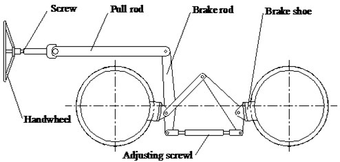
The existing handwheel-brake shoe brake device is shown in Fig. 1. The working principle is that, when the brake is needed, the driver rotates the handwheel to drive the screw, with the help of the pull rod and the brake rod, the brake shoe presses the wheel tread to achieve the brake.
Although the brake device has the advantages of simple structure, convenient maintenance and low cost, there are many deficiencies, which are mainly embodied in the following three aspects:
(1) The time of brake empty travel is too long.
At the time of braking. When the driver finds the situation, he starts turning the handwheel to brake shoe to press the wheel tread to brake. It takes about 3-4 s of time. Assuming that the vehicle speed is 16 km/h at this time, the distance of the empty stroke is 13.3-17.8 m, and the actual braking distance is only 22.2-26.7 m. This brings great safety risks to the transportation of mining electric locomotive.
(2) The layout of the brake shoe is unreasonable.
As the brake shoe is arranged on a single side, the force on the unit area of the brake shoe is larger in the process of braking. At this time, the temperature of braking point of working face of brake shoe will rise rapidly, and the braking effect will be reduced rapidly. In addition, due to uneven force on the brake shoe, local wear will occur. When the wear is serious, it is necessary to replace the brake shoe, resulting in a great waste of resources [1].
(3) The braking torque is too small.
It is necessary for the driver to rotate the handwheel manually to realize braking. Because the human arm strength is limited, the braking force provided is limited. In general, the braking force provided is difficult to meet the requirements of actual braking, resulting in a long braking distance of the mining electric locomotive, which can’t ensure the safety of its transportation under the mine.
Fig. 1Handwheel-brake shoe brake device
3. Analysis of the air disc brake device
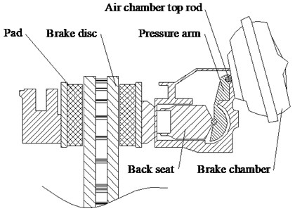
Considering the shortcomings of the existing braking device of mining electric locomotive, an air disc brake device is proposed. The structure of the air disc brake is shown in Fig. 2. The working principle is that, when braking is needed, the air chamber top rod of the brake chamber is extended, the thrust force of the air chamber top rod is amplified by the pressure arm and transmitted to the back seat, which drives the back seat to push the pad to press the brake disc to achieve the brake.
Fig. 2Air disc brake
It has many advantages to apply air disc brake to mining electric locomotive, which are mainly embodied in the following three aspects:
(1) The time of brake empty travel is short.
Using the air disc brake device, the system has a fast reaction speed when braking, it can shorten the time of brake empty travel effectively, and then shorten the distance of brake empty travel, so as to ensure the safe transportation of the mining electric locomotive under the mine.
(2) The brake torque is big.
Air disc brake device is used to instead of manpower to realize braking. The larger brake torque can be obtained, which can meet the requirements of actual braking of mining electric locomotive.
(3) The optimum parameters of the friction pair can be obtained.
According to the different braking requirements, the structure size of the pad and brake disc can be designed, and the material of the pad and brake disc is selected reasonably to obtain the optimum parameters of the friction pair and achieve a good brake [2].
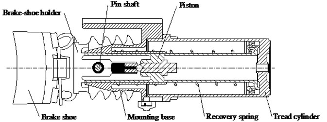
The environment under the mine is very bad. After changing the hand-wheel brake shoe brake device to the air disc brake device, in the process of working of mining electric locomotive, there will be a lot of dirt and oil trace on the wheel tread, which has caused a certain influence on the adhesion property between the wheel and rail. It affects the braking performance of mining electric locomotive. Therefore, a tread sweeper should be installed on the mining electric locomotive to scrape the oil stain on the wheel tread so as to ensure the stable adhesion property between wheel and rail, and to improve the braking performance of the mining electric locomotive. The structure of the tread sweeper is shown in Fig. 3. The working principle is that, when braking is needed, the pressure air on the right side of the tread cylinder pushes the piston to move to the left. With the help of the pin shaft, the piston moves the brake-shoe holder and brake shoe to the left to make the brake shoe contact with the wheel tread and scrape the wheel tread.
Fig. 3Tread sweeper
4. Calculation and analysis of braking performance
In order to verify the braking performance of the braking device, taking the ZK7-9/550 type trolley locomotive as the research object and referring to the theory and formula related to train traction braking [3-6]. The following calculation and analysis are carried out.
(1) Calculating the gravity of vehicle group according to adhesion condition of mining electric locomotive:
where is gravity of vehicle group, is gravity of locomotive, kN, is adhesion gravity of mining electric locomotive, when all wheel sets are active wheels, , kN, is adhesion coefficient, generally refers to sanding start, 0.24, is coefficient of drag of vehicle group at the start, 10.5, is thousand points of the average slope of track line, 3 ‰, is train starting acceleration, 0.04 m/s2.
The adhesion quality of ZK7-9/550 type trolley locomotive is 7 t, after calculation, the gravity of vehicle group can be obtained. 868.55 kN. According to the heating condition of the traction motor, the mining electric locomotive can pull 11 tramcars, the tramcar is 3 T fixed carriage type, its own weight is 1.32 t. Therefore, 475.2 kN.
(2) Calculating the unit brake force of mining electric locomotive.
Calculating the braking force that the air disc brake can provide:
where is air pressure, 0.5 MPa, is effective area of brake chamber, 3700 mm2, is drive ratio of pressure arm, 16, is transmission efficiency of air disc brake, 0.85, is friction coefficient of friction pair of air disc brake, 0.38, is number of pad.
Calculating the braking force that the tread sweeper can provide:
where is effective area of tread cylinder, 32360 mm2, is ratio of leverage, 1, is transmission efficiency of tread sweeper, 0.85, is friction coefficient of brake shoe of tread sweeper, 0.31, is number of brake shoe, 4.
Calculating the total braking force of mining electric locomotive:
Calculating the unit braking force of mining electric locomotive:
After calculation, the unit braking force of mining electric locomotive can be obtained, 101.41 N/kN.
(3) Calculating the braking distance.
Calculating the time of brake empty travel:
where is number of tramcar.
Calculating the braking distance:
where is initial speed of brake, selecting the maximum operating speed of mining electric locomotive, 16 km/h, is sequence number of the speed section, is total number of speed sections, is initial velocity of each velocity interval, km/h, is end velocity of each velocity interval km/h, is unit basic resistance of train, 3.1 N/kN, is thousand points of the average slope of a track line, selection the downhill slope, –3.
After calculation, the braking distance of mining electric locomotive can be obtained, 21.69 m. The brake distance of the handwheel-brake shoe brake device is 54.57 m. Compared with the proposed braking device, the braking distance is shortened by 32.88 m, and < 40 m, meet the requirements of Safety Regulations in Coal Mine.
5. Finite element analysis of disc brake
5.1. Theoretical basis of temperature field simulation of disc brake
(1) The establishment of a mathematical model of heat conduction.
Heat generated by friction is the process of converting mechanical energy into internal energy by overcoming friction and do work. For closed systems with no mass influx or outflow, they can be expressed as:
where is heat, is do work, is internal energy of the system, is kinetic energy of the system, is potential energy of the system.
There are three main types of heat transfer: heat conduction, thermal convection and thermal radiation. More than 90 % of the heat generated by the brake is absorbed by the disc brake, causing the temperature of the disc brake to rise gradually. Because the influence of thermal radiation is small relatively, it can be ignored. Therefore, only the effects of heat conduction and thermal convection are considered. The heat conduction differential equation of brake disc and pad can be expressed as:
where and are material density of the brake disc and the pad, and are specific heat of the brake disc and the pad, and are temperature of the brake disc and the pad, and are thermal conductivity of the brake disc and the pad, is braking time.
The density of heat flow rate input to the brake disc and the pad can be expressed as:
where is density of heat flow rate input to the brake disc, is density of heat flow rate input to the pad, is energy conversion efficiency, is input weight of the thermal flow of the brake disc, 0 ≤ ≤ 1, is friction force between the brake disc and the pad, , is relative running speed of pad and brake disc, m/s.
(2) Determination of boundary conditions.
During the braking process of disc brakes, with the conversion of mechanical energy to heat energy, the temperature of the brake disc rises rapidly in a short time, and these energy are consumed gradually in the way of heat transfer. The boundary condition of the working surface of the disc brake mainly includes two aspects. (a) There are natural heat conduction and the input of frictional heat between the brake disc and the pad. (b) Thermal convection between air and the surfaces of a non friction region:
where is contact thermal conductivity between the brake disc and the pad, is convective heat transfer coefficient on the friction surface of the brake disc, is ambient temperature around the brake disc.
The boundary condition between the cylinder surface outside the brake disc and the cylinder surface outside the pad usually considers the convection heat transfer with the air:
where and are outer normal line of the cylinder surface outside the brake disc and the cylindrical surface outside the pad, and are convective heat transfer coefficient of the cylinder surface outside the brake disc and the cylindrical surface outside the pad.
The boundary condition of friction surface are natural heat conduction and the input of frictional heat:
5.2. The establishment of finite element model of disc brake
According to the actual size of disc brake, the finite element model of disc brake is established. The model grid uses C3D8T, the total number of units is 18864, and the total number of nodes is 24840, as shown in Fig. 4. The material of the brake disc is HT250, and the material of the pad is semi metal composite material. The material performance parameters of disc brake are shown in Table 1 and Table 2.
Fig. 4Finite element model of disc brake
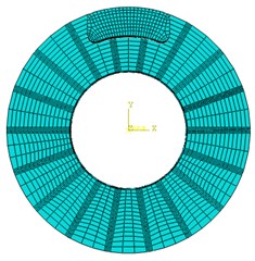
Table 1Material performance parameters of disc brake
Friction pair | Density / kg·m-3 | Poisson ratio | Friction coefficient |
Brake disc | 7220 | 0.25 | 0.38 |
Pad | 1550 | 0.16 | 0.38 |
Table 2Material performance parameters change with temperature of disc brakes
Friction pair | Temperature /℃ | Heat conductor coefficient / W·m-1·K-1 | Specific heat / J·kg-1·K-1 | Thermal expansion coefficient / 10-6 K-1 | Elasticity modulus / GPa |
Brake disc | 20 | 42.38 | 503 | 4.39 | 105 |
100 | 43.06 | 530 | 11.65 | 95 | |
200 | 44.23 | 563 | 12.84 | 90 | |
Pad | 20 | 0.8 | 900 | 20 | 0.6 |
100 | 1.04 | 1025 | 28 | 0.58 | |
200 | 1.17 | 1120 | 33 | 0.44 |
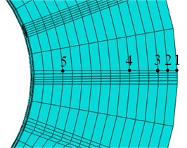
In order to understand the distribution of the temperature field on the surface of the brake disc, a number of nodes are selected in the radial direction of the brake disc, and the distribution of the nodes is shown in Fig. 5.
Fig. 5The position distribution of the nodes along the radial direction of the surface of brake disc
5.3. Analysis of temperature field of disc brake
According to the actual working condition of the mining electric locomotive, the working condition of the disc brake is set as follows: the initial angular velocity of the brake disc is 20 rad/s, and the pad is rubbed with the brake disc under the brake pressure of 25.16 kN, until the angular velocity of the brake disc is 0. The initial temperature is 20 ℃.
In the braking process of disc brakes, intercept two temperature distribution cloud chart at different time points, as shown in Fig. 6.
Fig. 6Temperature distribution cloud chart of disc brake
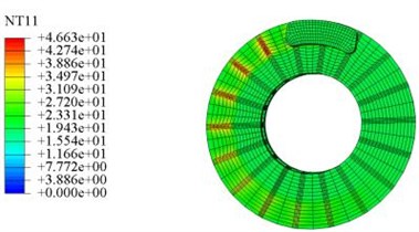
a) 0.25 s
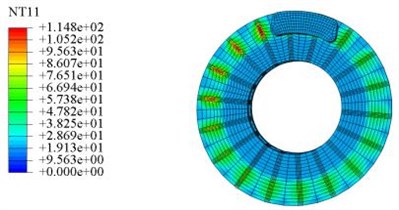
b) 1.5 s
It can be seen from Fig. 6 that during the braking process of disc brake, the temperature increases gradually, and the temperature at the ribs of the friction zone is higher. This is because the heat generated by friction between the brake disc and the pad is transmitted to the ribs in the form of heat conduction, causing the temperature at the ribs to rise rapidly over time. In addition, it can be seen that in the braking process of disc brake, the temperature of the friction zone between the brake disc and the pad is higher, and the temperature of the inner diameter of the brake disc is kept unchanged basically, because the braking time is short, and the friction heat cannot be transferred to the inner diameter of the brake disc in time.
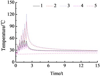
The curve of the temperature of each node along the radial direction of the brake disc with time is shown in Fig. 7.
It can be seen from Fig. 7 that in the braking process of disc brake, the temperature of nodes 1, 2, 3 and 4 in the friction region shows a zigzag trend that increases first and then decreases, which is due to the common effect of convection heat transfer and friction heat, and the temperature varies greatly. Because the node 5 is located outside the friction zone, it is less affected by friction heat, and the temperature change is not obvious. In addition, it can be seen that node 1 is located at the outside of the friction region, although its relative speed is the largest, but its temperature is not the highest. This is because the convection heat transfer effect in this location is better, and a part of the heat is transferred to the air, so that its temperature is lower than that of node 2 and node 3. The temperature at node 3 near the outside of the friction zone is the highest and reaches the maximum value of 121.4 ℃ at 1.99 s. Meet the requirement of The Specification of Narrow Tramroad Gauge Electric Locomotive for Mine that the temperature of the wheel tread and the friction surface of brake shoe should not exceed 150 ℃ after braking.
Fig. 7The curve of the temperature of each node along the radial direction of the brake disc with time
6. Conclusions
The ZK7-9/550 type trolley locomotive is taken as the research object and an air disc brake device and a tread sweeper are put forward. Through calculation verification and simulation analysis, it can be seen that the braking device can shorten the braking distance of mining electric locomotive effectively, which is in line with the requirements of the Safety Regulations in Coal Mine and it can meet the requirements of The Specification of Narrow Tramroad Gauge Electric Locomotive for Mine. Moreover, the brake device can scrape the oil stain on the wheel tread so as to ensure the stable adhesion property between wheel and rail. It has some reference significance for the improvement of braking system of mining electric locomotive in the future.
References
-
Wenjun W., Jishun L., Yi L., et al. Effect of brake shoe friction characteristics on brake temperature/stress field. Coal Technology, Vol. 36, Issue 1, 2017, p. 242-244.
-
Demao X., Ying X., Binbin H., et al. Effect of geometry and material properties of brake disc on thermoelastic instability of sliding frictional system. Journal of Jilin University (Engineering and Technology Edition), Vol. 46, Issue 4, 2016, p. 1163-1174.
-
Baosheng L., Baochun L. Discussion on calculation of mine electric locomotive traction. Mining Machinery, Vol. 38, Issue 9, 2010, p. 46-49.
-
Chenghao X. Analysis of transportation efficiency of CJY14/7 type mining electric locomotive. Mining Technology, Vol. 10, Issue 6, 2010, p. 63-64.
-
Dekun P. Mining electric locomotive selection and calculation. Coal Mine Machinery, Vol. 33, Issue 5, 2012, p. 31-33.
-
Yanhu L., Ligang C., Haiming Z. Structural optimization of foundation brake rigging for narrow-gauge industrial and mining electric locomotive. Mining Machinery, Vol. 40, Issue 6, 2012, p. 43-45.
About this article

