Abstract
The numerical simulation could help to understand the fracture mechanics behavior of high-pressure gas pipeline. The calculation results show that the internal high pressure of gas provides a driving force for crack propagation and tube wall deformation when the pipeline cracks and expands. Therefore, the rapid crack propagation tends to occur when the steel pipe is driven by high-pressure gas. In the process of steel pipe crack extension, immense internal high-pressure gas spewed from rupture and expand rapidly, compressing the air to form a series of compression wave which propagate rapidly and superpose together to form a shock wave eventually. Because the explosive wave of the pipe rupture has a high directivity, the energy distribution of gas is not uniform during the releasing process. What’s more, in pipe blasting, the longer distance, the more the surface vibration velocity decreases. In the vicinity of explosion source, the decreasing trend of the peak vibration velocity is significant. The vertical vibration velocity at the same point is larger than the longitudinal and tangential vibration speed.
1. Introduction
Gas pipeline has characteristics such as long conveying distance, big tube pressure and wide range of distribution. Once tube burst and other accidents occur, it is very easy to cause explosion and combustion, resulting in immeasurable loss of life and property. Due to the variability of the medium conditions and the complexity of the boundary conditions, it is impossible to solve the problem about high-pressure gas pipeline blasting accurately. There are also many restrictions in high-pressure gas pipeline blasting experiments, such as limited manpower, material resources and financial resources. The numerical simulation method can solve the problem with arbitrary geometrical conditions and arbitrary boundary conditions by utilizing the exceptional computing power of computers. Although the numerical simulation results are approximate, they are within the range of engineering accuracy.
Misama [1], starting from the essence of crack growth phenomenon, established a mathematical model of underground pipeline crack growth on the basis of certain experimental data, which can carry out iterative calculation of pipeline deformation and crack growth. What’s more, GASDECOM program is adopted to assist the calculation of gas decompression mode. Song and Belytschko [2] simulated crack and the crack propagation process of the thin-walled cylindrical shell under internal blast loading by extended finite element method, which has a good consistency with the experimental results. Mitsuya [3] calculated the dynamic stress intensity factor in the crack propagation by the finite element method, obtaining the stress distribution in the region near the crack tip. Fonzo [4], based on PICPRO program of Italian CSM, simulated a full-sized blasting experiment development of high-pressure internally air pipes. The simulation program considered the plastic deformation of the crack tip and introduced an area determined by material plastic viscosity, improving the precision of the calculation. Yang Xiao-bin [5], based on the three linear pressure mode, explored the dynamic extension of rich-gas pipeline crack by finite element calculation model. It proved that the rich-gas transportation pipeline is harder to crack, but based on the pressure attenuation area, linear attenuation relationship in reduced pressure zone can improve. Shuai Jian [6] established finite element model about the dynamic extension of pipeline crack and simulated the cracking by the node release technology.
Based on the correct establishment of the dynamic finite element numerical calculation model, this paper studies the characteristics of the physical explosive shock wave and the formation and propagation mechanism of the explosive seismic wave in high-pressure gas pipeline, so as to provide important reference for solving such problems.
2. Numerical simulation
2.1. Finite element model
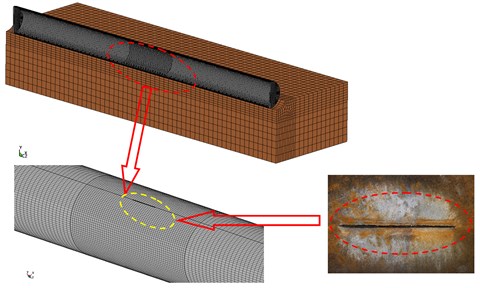
Based on the characteristics of the research problem, it adopted the coupling algorithm of Euler voluminous materials and Lagrange structure. The interaction between the external air medium, gas pipe and rock structure are coupled. In view of the symmetry of the physical model, it established a calculation model of one-half of the desirable prototype and adopted the g-cm-s system. Set the symmetric constraint on the symmetric face and define the air and the dielectric as the transmission boundary. Fig. 1 shows the partition of steel pipe structure and surrounding soil by SOLID164 six-sided entity unit. In addition, according to the actual effect of the linear shaped explosive cutter on the steel pipe, preset a crack with a length of 50 cm and a width of 1 cm on the center of upper surface of the steel tube structure in the numerical calculation model.
Fig. 1The finite element model
2.2. Material behavior
When the pipe breaks, a large amount of high-pressure gas inside the pipe will rapidly expand from the crack. In the numerical simulation, JWL state equation is applied to determine the pressure change in the steel tube during the high-pressure gas leak blasting. The expression is shown as the followed:
where , , , and are material constants, is the pressure, is the relative volume of detonation product and is the specific energy with an initial value of .
In the numerical model, establish models by an ideal gas EOS, which is one of the simplest forms of EOS. The pressure is related to the energy by the followed:
where is a constant, is air density and is the specific internal energy. In the simulation, the value of is 1.225 kg/m3 and the value of is 1.4. The air initial internal energy is assumed to be 2.068×10⁵kJ/kg.
Based on the rock and soil properties, adopt a plastic hardening model to simulate rock and soil. The stress and the strain rate have the following relationship:
where , are the Cowper-Symonds strain rate parameters; is Yong modulus; is the initial yield stress; is applied strain rates; is the plastic hardening modulus.
To describe the various phenomena occurring during contact explosion, it is necessary to characterize the behavior of materials under the condition of explosion-generated high strain rate loading. Tube steel is modeled by the Johnson-Cook which is suitable to simulate the strength behavior of materials subjected to large strains, high strain rates and high temperatures. The model defines the yield stress as the followed:
where , , , and are material parameters determined by experiments. is the dimensionless effective strain rate and is the homologous temperature which is defined by:
where and are the room and melting temperatures, respectively.
In the fracture analysis, Johnson-Cook fracture model is used. Based on the concept of cumulative damage, the model take account of the loading history involving variations in strain rate, temperature and pressure. The damage parameter is defined by:
where is the increment of effective strain caused by the tensile load and is the effective fracture strain in the instantaneous conditions. When 1, fracture occurs.
3. Numerical simulation results and analysis
3.1. The crack propagation and damage of steel pipeline
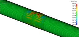
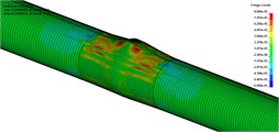
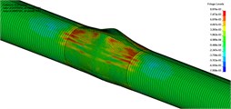
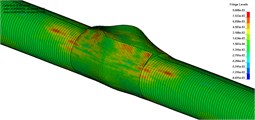
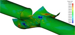
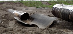
Fig. 2 shows the deformation and damage of steel pipeline at a typical moment, and compares the final deformation of steel pipeline with experimental results. Calculated by the numerical simulation, when the pipeline generates axial crack and the crack expands, the pressure of internal high-pressure gas provides a driving force to crack propagation and tube wall deformation. Driven by high-pressure gas in the tube, rapid crack propagation phenomenon occurs in X90 steel tube. The long-range extending axial crack caused by physical explosion is the symbol of discrepant failure modes between high-pressure gas transmission pipeline and liquid transportation pipeline, and the failure of pipe wall is closely related to the crack growth and the process of deformation. It is implied in the numerical simulation that the steel tube bears 12 MPa pressure. The crack starts from the two tips of the initial crack and extends along the axial line of the steel tube. When the crack extended to the position of the ring weld, the ring cutting occurs and the results are in good agreement with the phenomena. The numerical simulation and experimental results are in good agreement with each other, which confirms the effectiveness of this method.
Fig. 2The deformation and damage of steel pipeline at typical moment and analysis compared with experimental results
a)
b)
c)
d)
e)
f)
g)
h)
i)
3.2. Analysis of the expansion process and shock wave characteristics of the internal high-pressure gas
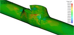
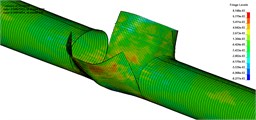
Fig. 3 shows the spray and expansion of the internal high-pressure gas during the process of crack propagation and compares the final deformation of steel pipeline with experimental results. The results of numerical calculation are consistent with the actual phenomenon.
Fig. 3Injection expansion process of the internal high-pressure gas
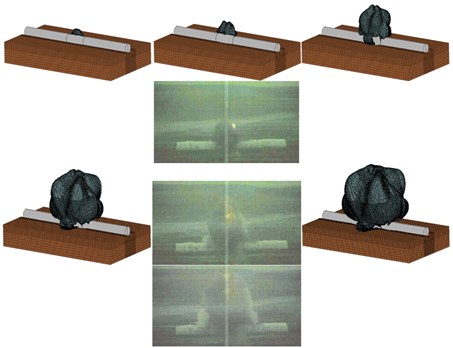
It is yielded in the calculation results that during the crack propagation process, the closer the crack tip is, the smaller the opening distance is, and the whole crack seem like a diamond. If the pipe is broken, a large number of high-pressure gases in the pipe will spew out rapidly from the crack. At the initial stage of the gas expansion, the compressed air mass ejected from the crack is similar in shape to the fracture which seems like a diamond. The gas pipeline is actually a kind of pressure vessel, but it has a large diameter, and the mechanism of physical explosion is similar to that of a pressure vessel. When the pipeline breaks, a large number of internal high-pressure gas will spew from rupture and expand rapidly, compressing the air to form a series of compression wave which propagate rapidly and superpose together to form a shock wave eventually.
The calculation results show that in the tube rupture of the initial stage, there are some characteristics such as large gas pressure, fast expansion and the formation of large overpressure. Subsequently, the gas leakage pressure and the expansion velocity decreases, and a shock wave is formed at the instant of the pressure wave superposition process, so the subsequent gas leakage will form a series of smaller peaks in the process of overpressure expansion. It shows that because the explosive wave of the pipe rupture has a high directivity, the gas energy is not uniform during the releasing process. The phenomena above is mainly related to the shape and cracking mode of the pipeline, which is different from the explosion of the gas pipeline and the strong explosion of ordinary high-energy explosive.
3.3. Characteristics of blasting seismic waves
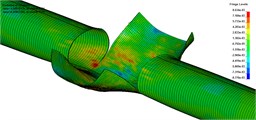
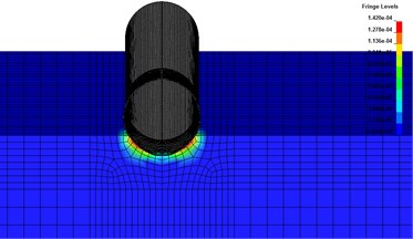
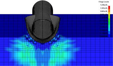
Fig. 4 shows the impact of the steel tube deformation on the surrounding rock and soil. According to the calculation results, when the pipeline burst, under the influence of high-pressure gas which is compressed strongly, the wall of the pipe rapidly opens, and the compressed gas injected at high speed, which has a huge impact on the surrounding rock and soil, thus forming the stress wave in the burst area. As the propagation distance increases, the impact energy propagated in the form of seismic waves. The propagation of seismic wave in rock and soil will cause vibration of medium body, resulting in vibration near buried pipeline or other building structures. When reaching certain intensity, it will cause structural deformation to be too large and fail.
Fig. 4The impact of the steel tube deformation on the surrounding rock and earth medium
a)
b)
Fig. 5Vibration velocity peak-value comparison of calculation results and experimental data
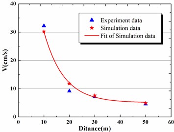
The velocity of the surface vibration decreases as the blasting position is far away from the pipe. Near explosion source, the decreasing trend of the peak vibration velocity is significant. At the same point, the vertical vibration velocity is larger than the longitudinal and tangential vibration speed. Therefore, vertical maximum vibration speed is the main factor to evaluate the damage degree of steel pipe blasting.
As showed in Fig. 5, the vibration velocity peak-value of calculation results and experimental data are in good agreement. It proved again that the numerical simulation method provided in this paper has high computation accuracy.
4. Conclusions
1) The simulation calculation results are in good agreement with the experimental data, which provide a new method to study the damage effect of the pipe blasting. The calculation results show that the internal high-pressure gas pressure provides a driving force for crack propagation and tube wall deformation when the pipeline cracks and expands, and the crack propagation will occur rapidly when the steel pipe is driven by high pressure gas.
2) The calculation result shows that in the process of steel pipe crack extension, a large number of internal high-pressure gas spewing from rupture rapidly expand, compressing the surrounding air to form a series of compression wave, the superposition of which eventually form a shock wave. The explosive wave of the pipe rupture has a high directivity, and the gas energy is not uniform during the releasing process. The phenomena above is mainly related to the shape and cracking mode of the pipeline, which is different from the explosion of the gas pipeline and the strong explosion of ordinary high-energy explosive.
3) In pipe blasting, the longer distance, the more the surface vibration velocity decreases. What’s more, near explosion source, the decreasing trend of the peak vibration velocity is significant. The vertical vibration velocity is larger than the longitudinal and tangential vibration speed at the same point.
References
-
Misawa K., Imai Y., Aihara S. A new model for dynamic crack propagation and arrest in gas pipeline. International Pipeline Conference, 2010, p. 685-694.
-
Song J. H., Belytschko T. Dynamic fracture of shells subjected to impulsive loads. Journal of Applied Mechanics, Vol. 76, Issue 5, 2009, p. 051301.
-
Mitsuya M., Motohashi H., Oguchi N., et al. Calculation of dynamic stress intensity factors for pipes during crack propagation by dynamic finite element analysis. Journal of Pressure Vessel Technology, Vol. 136, Issue 1, 2014, p. 011207.
-
Fonzo A., Meleddu A., Di Biagio M., et al. Crack propagation modeling and crack arrestor design for X120. International Pipeline Conference, 2006, p. 317-325.
-
Yang Xiaobin, Zhuo Zhuang, Zhuang Chuan Jing Numerical Simulation on dynamic crack extension of rich gas transmission pipeline. Journal of Tsinghua University: Natural Science Edition, Vol. 48, Issue 8, 2008, p. 1355-1358.
-
Shuai Jian, Zhang Hong, Xu Kui Numerical simulation of dynamic cracks propagation in gas transmission pipeline. Oil and Gas Storage and Transportation, Vol. 23, Issue 8, 2004, p. 5-8.
-
Shuai Jian Test study on the resistance curve of pipeline steel crack propagation. Natural Science Edition of China University of Petroleum Journal, Vol. 37, Issue 5, 2013, p. 168-174.
About this article

This research was financially supported by the National Nature Science Foundation of China, Nos. 51678567, 11102233 and 51608530.
