Abstract
A piston type explosive bolt is modeled by using a hydrocodes AUTODYN. The influence of the charge amount on the separation shock is analyzed. The results show that the separation shock of the piston type explosive bolt mainly includes two aspects: the shock caused by explosive detonation and the impact of the piston at the end of stroke. As the charge amount increases, the collision speed of piston first increases and then decreases, and the separation shock first increases and then stabilizes.
1. Introduction
A piston type explosive bolt is a simple, highly reliable and efficient pyrotechnic release device widely used in aerospace industry [1, 2]. High frequency and high amplitude transient shock is generated during the separation, known as pyroshock that can easily cause damage to nearby micro components [3, 4]. Many researchers have analyzed shock propagation and assessed damage by a large number of test [5-11], mainly adopted two kinds of protection measures such as propagation path isolation and instrument installation isolation [12, 13].
With the application of lightweight space structures, the measures to mitigate the shock at the sources without additional structures are favored. Due to the highly nonlinear characteristics of combustion and explosion, it is difficult to accurately analyze in theory and monitor the internal dynamic parameters. The nonlinear dynamic simulation brings a feasible approach. Han [14-17] used AUTODYN to study the shock generation and propagation characteristics of the “ridge-cut” explosive bolt. Wang [18] used LS-DYNA to analyze the three different shock sources of a shear pin type explosive bolt. Zhu [19] analyzed the influence of detonation sequence and interval on the separation shock of several fragmenting type explosive bolts by established a SPH-FEM coupling model. Huang [20] analyzed the effect of pre-tightening force on the output shock of a shear pin type explosion bolt by LS-DYNA. The piston type explosive bolt involves internal component movements, and its shock generation mechanism is more complicated. There are currently few published studies.
In this study, the separation behaviors of a piston type explosive bolt are simulated by hydrocodes AUTODYN, and the effect of the charge amount on separation velocity and separation shock are especially analyzed.
2. Structure and working principle
A piston type explosive bolt is shown in Fig. 1. It is mainly composed of ignitor, pyrotechnic component (including main charge PETN), piston, seal ring, body and lock nut. The material of body and piston are 4340 steel. A circumferential groove, referred to as impair slot, is prefabricated on the side wall of the body. When the release separation is required, the ignitor is energized to detonate the main charge, and the explosion shock wave and the gas product expansion jointly push the piston to break the bolt at the impair slot, thereby achieving separation.
Fig. 1Structural schematic of explosive bolt
Fig. 2Numerical models of explosive bolt
3. Numerical modeling
In order to simplify the model, the energy generated by the combustion or explosion of primers and booster is converted into main charge, and the sealing ring and others is deleted. The fluid-solid coupling algorithm of AUTODYN is used to compute the coupling of fluid and structure. A 1/4 axisymmetric model is established, as shown in Fig. 2. The body and piston are modeled as Lagrange elements. The main charge and air domain are modeled as Euler elements. In order to study the separation shock characteristics, the explosive bolts were mounted in the center of a 60 cm×60 cm×1 cm square 2024 aluminum alloy plate suspended by four bungees. The three piezoresistive accelerometers in three different positions 5, 10 and 15 cm from the bench center, as shown in Fig. 3. According to the test setup, a numerical model is established, as shown in Fig. 4. The , acceleration histories are extracted from the set monitoring points at four different positions 2, 5, 10 and 15 cm from the center. The acceleration histories with a uniform time step (1 μs) are obtained by utilizing cubic spline interpolation. The improved recursive filtering algorithm was used to calculate the shock response spectrum (SRS) [9].
The product of the PETN is descried by the JWL equation of state. The dynamics behavior of 4340 steel and 2024 aluminum was described by Johnson-Cook strength model and Shock state equation. Johnson-Cook failure model is used to describe the piston failure the air is described by ideal gas state equation. All parameters are taken from the AUTODYN material database.
Fig. 3Measurement scene of separation shock
Fig. 4Analysis models of separation shock
4. Results and analysis
4.1. Separation process
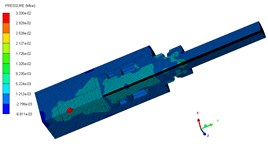
The pressure contours of the explosive bolt during separation processes are shown in Fig. 5. At 0 μs, the charge was detonated. Then, the propagation of detonation waves and the expansion of products started at 1us (Fig. 5(a)). The shock waves propagate reached the end face of the piston and the products fills the entire chamber around 3 us (Fig. 5(b). Then, the shock wave and expansion of products drove the piston to move forward, and a tensile stress is formed at the pre-groove. The pre-groove reached the failure criterion and began to fail around 70 us (Fig. 5(c)). At 83 us, the failure expands radially along the groove, eventually forming a fracture and starting separation (Fig. 5(d)). As the fracture is formed, the piston accelerated forward and released the screw free. At 155 μs, the piston hits the body shoulder, the velocity instantaneously decreased and eventually stopped moving (Fig. 5(e)). When the piston stopped moving, the screw is no longer subjected to the loading force and kept flying at a constant speed (Fig. 5(f)).
Fig. 5Pressure contour on separation process
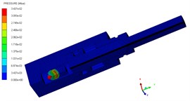
a) 1 μs
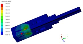
b) 3 μs
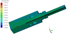
c) 70 μs
d) 83 μs
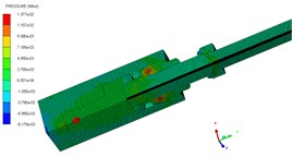
e) 155 μs
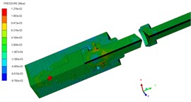
f) 200 μs
4.2. Analysis of shock sources
When the charge amount is 442 mg, the shock acceleration history and SRS in the and directions at 2 cm were shown in Fig. 6. It can be clearly seen from the acceleration history that there are two distinct peaks. Combined with the simulation of the separation process in Section 4.1, it can be seen that the two peaks are caused by the pyrotechnic explosion and the piston impact. In addition, the shock response in the direction is significantly larger than in the direction. This is because is the main direction of the explosion shock wave propagation and piston impact.
Fig. 6Output shock of explosive bolt in test
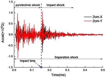
a) Acceleration history
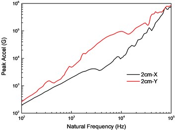
b) SRS
4.3. Comparison of simulation and experiment
The SRS obtained by simulation and experiment at 5, 10 and 15 cm are compared in Fig. 7. The experimental SRS is enveloped by the ±6 dB of simulated SRS except for the individual frequencies, which indicates that the simulation model can predict the separation shock.
Fig. 7Comparison of SRS between simulation and experiment
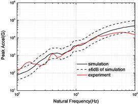
a) 5 cm
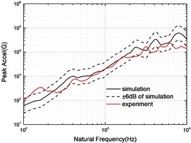
b) 10 cm
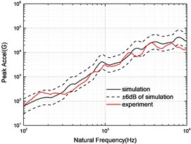
c) 15 cm
4.4. Effect of charge amount on piston velocity
From the analysis of shock source in the section 4.2, it is known that the peak velocity of piston has a great influence on separation shock. The variation law of the piston velocity during the separation process under a 442 mg charge amount is analyzed, and the results shown in Fig. 8. The piston velocity first rised to about 20 m/s under the action of the detonation shock wave and the product expansion. Then, the front end of body was loaded to stretch the impair slot. At 70 us, the impair slot begins to fracture, the velocity of piston rised sharply, and finally the body was broken. The speed then drops sharply when the piston hit the body shoulder. However, due to the deformation of the body caused by the impact (Fig. 5(f)), the piston continued to move forward for a distance until it stopped.
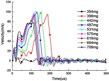
The velocities of the piston for different charge amounts were calculated, and the results are shown in Fig. 9. As the charge increases, the piston velocity in the early stage increased, but the velocity of the piston collision does not continue to increase, reached at the maximum at 531 mg. When the design stroke is fixed, the overall velocity of the piston is larger as the charge amount is increased, but the collision time is advanced, so that the collision velocity does not necessarily increase.
Fig. 8Piston velocity and displacement in 442 mg
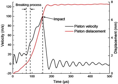
Fig. 9Piston velocity in different charge amount
4.5. Effect of charge amount on separation shock
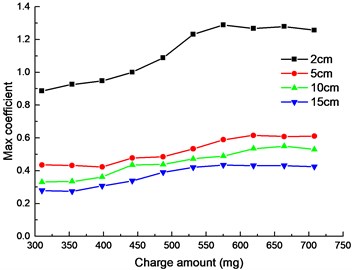
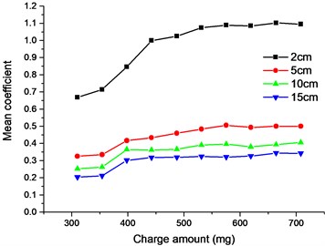
The acceleration of direction at four different distances from the source was extracted under different charge amounts, and the corresponding SRS calculated. To better study the influence of the charge amount on separation shock, two dimensionless coefficients of and that does not consider the frequency were defined. The expression is as follows:
where, is the maximum relative coefficient of the SRS and is the average relative coefficient of the SRS in the entire frequency domain. is reference SRS. Here, the reference SRS is the SRS of the 442 mg charge amount in the direction at 2 cm.
The and at four locations were calculated and are shown in Fig. 10.
It can be seen from Fig. 10 that the influence of the charge on the shock is not a simple linear relationship in terms of or . The explosive bolt is not separated when the charge was 310 and 354 mg. Their separation shocks are basically consistent except for the near field 2 cm. Since the shock in the unseparated condition is only caused by the explosion shock wave, the shock wave dissipates quickly as the distance increases. The near-field shock response is directly affected by the shock wave, while the far-field shock response is mainly dominated by the stress wave and the structural resonance. When the charge was increased from 354 to 398 mg, the shock sharply increased because the explosion bolts achieved separation, and the shock caused by the impact of the piston was introduced. In the case of separation, the separation shock first increased with increasing charge amount and then tends to stabilize at 531 mg. Although the explosion shock increased as the charge amount increased, but the impact shock decreased as the impact speed of piston decreased. The combined result of the two causes resulted in an output shock that remained essentially unchanged.
Fig. 10Relationship curves between SRS and charge amount
a) Max coefficient
b) Mean coefficient
5. Conclusions
In this paper, a piston type explosive bolt was modeled by a hydrocodes AUTODYN. The influence of the charge amount on the separation shock was especially analyzed. The results show the following:
1) The sources of the output shock of the piston type explosive bolt mainly includes two aspects: pyrotechnic explosion and piston impact.
2) Under the constant stroke of the internal piston, as the charge amount increases, the collision velocity of the piston first increases and then decreases, and there is a maximum value.
3) The relationship between charge amount and separation shock is not a simple linear relationship, but first increases and then stabilizes.
References
-
Bement L. J., Schimmel M. L. A Manual for Pyrotechnic Design Development and Qualification. NASA, New York, 1995.
-
Liu Z. S., Wang X. J., Zhu X. C., et al. Aerospace Pyrotechnic Devices. Chinese Astronautics Press, Beijing, 2012.
-
Moening C. J. Pyrotechnic shock flight failures. Institute of Environmental Sciences Pyrotechnic Shock Tutorial Program in 31st Annual Technical Meeting, Washington, 1985.
-
Piersol A. G., Paez T. L., Harris C. M. Harris’s Shock and Vibration Handbook. Sixth Edition, McGraw-Hillm, New York, 2010.
-
Gentz S. J., Ordway D. O., Parsons D. S., et al. Empirical Model Development for Predicting Shock Response on Composite Materials Subjected to Pyroshock Loading. NASA, New York, 2015.
-
Hughes W. O., McNelis A. M. Statistical Analysis of a Large Sample Size Pyroshock Test Data Set Including Post Flight Data Assessment. NASA, New York, 1998.
-
Ryschkewitsch M. G. Pyroshock Test Criteria. NASA, New York, 2011.
-
MIL-STD-810G Method 517.1. Department of Defense, New York, 2008.
-
Pyroshock Testing Techniques. Institute of Environmental Science and Technology, Arlington, 2009.
-
Laboratory Environmental Test Methods for Military Materiel-Part 27: Pyroshock Test. The Chinese People’s Liberation Army in the Equipment Department, Beijing, 2009.
-
Lee J. R., Chia C. C., Kong C. W. Review of pyroshock wave measurement and simulation for space systems. Measurement, Vol. 45, Issue 4, 2012, p. 631-642.
-
Zhang H., Liu T. X., Li C. J., et al. Status and application analysis of spacecraft pyroshock protection techniques. Spacecraft Engineering, Vol. 23, Issue 2, 2014, p. 104-113.
-
Zhang H., Li C. J., Liu T. X. Review of spacecraft pyroshock reduction technique. The Academic Seminar on Reliability Technology of Machinery Industry, Chengdu, Chian, 2013, p. 220-229.
-
Lee J., Hwang D. H., Han J. H. Numerical study on pyroshock generation and propagation from pyrotechnic release devices using hydrocodes. Proceeding of the 21nd International Congress on Sound and Vibration, Beijing, China, 2015.
-
Lee J., Hwang D. H., Jang J. K. Pyroshock prediction of ridge-cut explosive bolts using hydrocodes. Shock and Vibration, Vol. 2016, 2016, p. 1218767.
-
Lee J., Hwang D. H., Han J. H. Study on pyroshock propagation through plates with joints and washers. Aerospace Science and Technology, Vol. 79, 2018, p. 441-458.
-
Lee J., Hwang D. H., Jang J. K., et al. Nondestructive evaluation of pyroshock propagation using hydrocodes. Proceedings of Active and Passive Smart Structures and Integrated Systems, 2016, https://doi.org/10.1117/12.2219022.
-
Wang J. P., Mao Y. J. Huang H. J. Numerical simulation for impulsively loading mechanism of a point pyrotechnic separation device. Journal of Vibration and Shock, Vol. 32, Issue 2, 2013, p. 9-13.
-
Zhu D. J., Chu W. H., Liang D. L., et al. Characteristics of a vehicle’s pyroshock based on SPH-FEM coupled method. Journal of Vibration and Shock, Vol. 34, Issue 11, 2015, p. 68-74.
-
Huang H. J., Wang J. P., Mao Y. J., et al. Influence of pretightening force of explosive bolts on impulse response. Journal of Vibration and Shock, Vol. 34, Issue 16, 2015, p. 166-169.
Cited by
About this article

