Abstract
A numerical parametric analysis of a vibro-acoustic coupling method that considered the influence of vibro-acoustic coupling was carried out to investigate the casing vibrations and feathers of vibrational noise induced by unsteady flow of the centrifugal fan at the best-efficiency point (BEP). There are three important aspects of this method. First, an unsteady flow-field with a whole impeller-volute configuration was solved based on three-dimensional incompressible Navier-Stokes equations and a standard - turbulence mode to obtain the source of the vibro-acoustics. Second, a one-way-flow structural acoustic coupling method was implemented to study the volute vibrations and behaviors of vibrational noise by adoption. The generation mechanism of vibrational noise of the volute casing was revealed. Third, the parametric analysis method was used to explore the parametric relationship between the panel thicknesses (such as front-panel thickness [FT], side-panel thickness [ST], and back-panel thickness [BT]) and the outlet acoustical power of the volute casing surface. The parametric analysis provides a reasonable range of values of three panel thicknesses that result in minimal vibrational sound radiation.
1. Introduction
In certain application environments, the unsteady-flow-induced vibrational noise is also not negligible. As the fan system inlet and outlet are entirely connected to the extended pipe, internal aerodynamic noise cannot be directly transmitted to the outside. At this moment, the fan casing and the inlet and outlet pipe vibration noise caused by the vibration result from the internal unsteady flow is predominant. Therefore, it is necessary to conduct an in-depth study of the generation mechanism of the vibration noise and a noise-reduction method. In fact, the fan noise induced by unsteady flow is fluid-structure coupling noise, and the impeller and volute can be classified as an elastomer, and in particular, the volute vibration cannot be neglected in large fans [1]. There are few studies of the vibration noise induced by the vibration of the casing in a centrifugal fan. However, this type of noise is prominent in large-scale fan systems. At present, research on vibration noise induced by casing vibration resulting from impeller outlet unsteady flow is usually produced using a calculation method [1-4]. These studies have contributed to the study of flow-induced elastic casing vibration and noise radiation, facilitating a deeper understanding of noise radiation with centrifugal fans running, and providing a useful reference for noise reduction of such turbomachinery. However, flow-induced vibration noise and casing vibration are multi-disciplinary cross-coupling problems. There are few researchers studying noise-generation mechanisms and the discrimination of the location of noise sources reviewing the literature collected at home and abroad. Therefore, it is necessary to carry out in-depth research of these problems.
The purpose of vibration noise research is to explore the generation mechanism of vibration noise, then propose targeted methods of vibration and noise reduction. At present, a structural vibration control method is desirable. Current structural vibration control is focused on structural optimization. A centrifugal fan casing belongs to a thin-casing structure, while the vibration sound power of the thin-casing structure is a quadratic function of the structural vibration velocity [5, 6]. The effect of noise reduction of the casing is achieved by the aforementioned optimization methods, which set the vibration response (node vibration speed) as the objective function by reducing the fan casing vibration. However, this method does not consider the propagation of sound waves and the sound boundary effects on the calculation results, so there is a certain error in the calculation. Multidisciplinary structure-acoustic optimization correctly mitigates these drawbacks [7-9]. Combining the aforementioned optimization advantages, the author proposes a vibration-acoustic integrated optimization design method that is suitable for turbomachinery vibrational noise reduction. This parametric study is fundamental research for volute vibrational noise optimization, providing a basic database and scope of variables for optimization.
2. Description of the numerical simulation procedure
Fig. 1. Shows the model of the studied fan, and the main dimensions and characteristics of the investigated fan for this study are presented in Table 1.
Fig. 1Component representation for the test fan
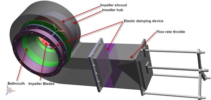
Fig. 2Sketch of CFD grids at the meridian plane
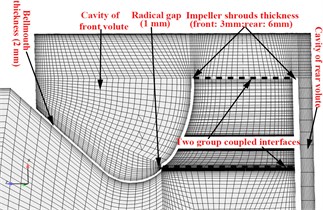
Fig. 3Detail of geometric features
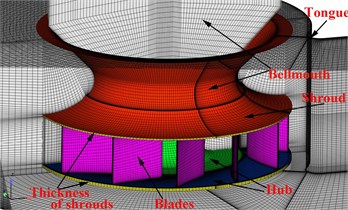
Table 1Fan dimensions
Impeller blade outlet diameter (mm) | 520 | Impeller blade inlet diameter (mm) | 328 |
Impeller outlet width (mm) | 102 | Impeller inlet width (mm) | 138 |
Blade number | 12 | Volute width (mm) | 286 |
Impeller-tongue distance (mm) | 38 | Impeller-tongue distance (% of ) | 13.2 % |
In this paper the complete unsteady flow for the entire impeller-volute configuration was conducted using the computational fluid dynamics (CFD) code ANSYS CFX. The code numerical simulation is based on a finite-volume numerical method that employs an incompressible turbulent flow model to solve the continuity equation and the three-dimensional time-averaged Navier-Stokes equations. The Standard - turbulence model, which was applied to capture wall pressure fluctuations, was used in the present simulation of the unsteady flow field. A second order high-resolution discretization scheme was used for the convection terms, and a second order backward Euler scheme was used for the transient terms. For the three-dimensional calculations, a couple of high quality hexahedral structural grids were employed to define the flow domains. Details of the grid features and meridian grid cross-section, including the radical gap and cavity around the volute, are shown in Figs. 2 and 3. Numerical deviations strong connections with the grid number needed to be removed, and a grid-independent validation of the fan total pressure coefficient and efficiency was performed. Fig. 4 shows that the grid was independent when the total number of grid points exceeded 2.8 million. In addition, by increasing the grid size to 5.7 million, the total pressure coefficient with respect to the flow rate was nearly unchanged, compared with the smaller total pressure coefficient over a small flow rate range close to the best efficiency point (BEP).
Fig. 4Grids size independent
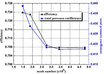
a) Fan total pressure and efficiency with grids size
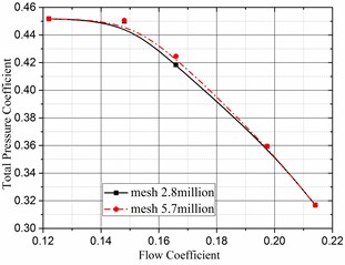
b) Total pressure coefficient with flow rate
In this case, the CFD simulation process began with a steady flow calculation using the frozen-rotor approach, and nonslip conditions were specified at the solid walls. In addition, for the near-wall flow region, a scalable wall function treatment based on the logarithmic law was applied to cause the mean value of Yplus to vary between 30 and 300. For the unsteady flow, a transient rotor/stator grid interface based on sliding grid technique was applied, which allowed unsteady interactions between the impeller and volute casing. A time step of 5.7089e-5 s (the time step was specified such that the impeller rotated once in 360 steps (a blade passage defined 30 steps)) was used for the calculation of the unsteady interactions, which was sufficient for the dynamic analysis. The unsteady simulation was initialized using a steady solution, and over 15 revolutions (approximately 5400 time steps) were required to converge on a periodic unsteady solution. Using the defined test bench (previous work (Jianhua Zhang et al.) [10]), the overall performance of this fan predicted by the CFD calculations was compared for different flow rates. Fig. 5 indicates that the measured total pressure coefficient and efficiency agreed well with the three-dimensional steady-state calculations especially at the BEP. More details about grids, boundaries, the comparison and the results discussion have been reported in the previous work (Jianhua Zhang et al.) [10].
Fig. 6 shows the numerical evaluation method of volute vibro-acoustic coupling. It can be seen that the flow-structure-acoustic unidirectional coupling method is divided into three main steps: the first is to acquire the fluid-structure coupling vibration source of the volute surface caused by the unsteady flow field; the second is to interpolate the frequency domain pressure placed on the flow nodes of the volute surface to the structural nodes according to the Eq. (1) algorithm (where ( 1, 2, 3, 4) is the pressure load of the source node, is the pressure load of the target node, and di ( 1, 2, 3, 4) represents the distance from the source node to the target node; Fig. 7 shows the diagram of the geometric interpolation algorithm) and then use FEM to obtain volute structure modal information; the third is to calculate the vibrational sound radiation using the modal superposition method.
In this study, NX Nastran, a commercial code, was used to calculate the mode and vibration of the volute. A high-quality surface tetragon mesh was selected to establish the volute FEM model, as is shown in Fig. 8. The FEM model of the volute panel is divided into three main parts by the thickness of each part, including 6 mm, 6 mm, and 5 mm. All of the three panels divided a total of 46,182 shell63 elements. The modal material is steel, where density 7800 kg/m3, elastic modulus 2.06×10¹¹Pa and Poisson’s ratio 0.3. The volute casing was fixed to a supporting stand by ten fastening bolts at the casing front. The volute panel rear (near the motor) was connected by four fixed bolts; the three translational degrees of freedom of the nodes at the bolts were restricted to zero. The panel thickness distribution and the degree of freedom constraints on the volutes are shown in Fig. 8.
Fig. 5Comparison between numerical and experimental curves
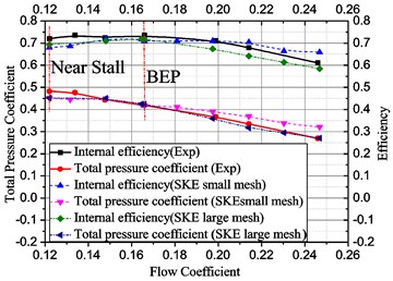
Fig. 6The flow chart of numerical evaluation method of volute vibro-acoustic
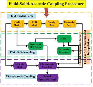
Fig. 7The diagram of the geometric coupling interpolation algorithm
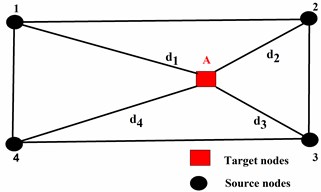
Fig. 8Volute FEM model
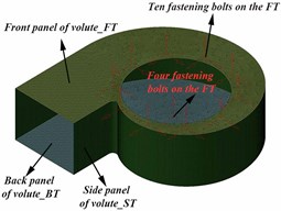
Fig. 9 shows a comparison between the numerical and experimental results of the total vibration level spectrum from 20 to 3000 Hz. It can be seen that the numerical and experimental vibration of the volute casing show good agreement. Therefore, the FEM model of this study can effectively predict the vibration induced by the unsteady flow of the impeller. More details about the comparison and the results discussion have been reported in the previous work (Jianhua Zhang et al.) [11].
The volute acoustical FEM mesh is shown in Fig. 10. Considering the radiation of vibration noise, the volute inlet and outlet are completely closed. The mesh was comprised of 816,165 linear tetrahedral elements. More importantly, the computational acoustic mesh had to satisfy a requirement of element size driven by the maximum frequency (e.g., 6 points per wavelength). An acoustic-mesh with a maximum element size of 15 mm was applied in the sound computation and guaranteed a spatial resolution at a maximum frequency 3236 Hz of 6 points per wavelength.
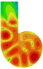
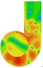
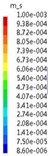
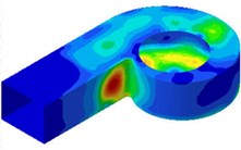
Fig. 11 presents the spectrum program of vibrational sound radiation of the volute casing; it can be concluded that the vibrational noise at the fundamental frequency ( 584 Hz) is obvious. So, the Fig. 12 presents the distribution of the vibrational sound radiation of the volute casing surface at the fundamental frequency ( 584 Hz). It can be seen that there are very strong vibrational acoustic radiation values at the outlet of the volute side panel near the volute tongue region and the volute back panel at 180° from the tongue. Fig. 13 show the amplitude distribution of the normalized velocity. This figure show that the distribution shape of the surface sound pressure and surface normal velocity on the volute have identical characteristics.
Fig. 9The compassion of numerical and experimental amplitude of normal acceleration
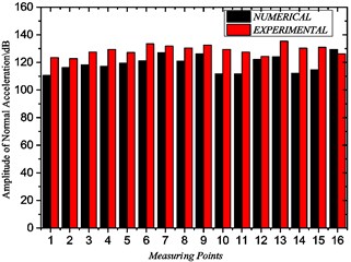
Fig. 10The volute acoustical FEM mesh
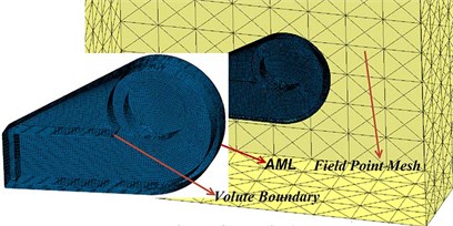
Fig. 11The spectrum program of vibrational sound radiation
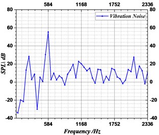
Fig. 12The distribution of the vibrational sound radiation of the volute casing surface at BPF
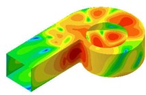
a) Side
b) Back
c) Front
Fig. 13The distribution of the vibrational velocity of the casing surface at BPF
a) Side
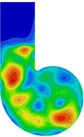
b) Black

c) Front
Therefore, it can be concluded that the normal vibration of the volute was the decisive factor that determined the volute surface acoustic radiation. Therefore, the mechanism of the generated volute vibration noise can be summarized as follows: the unsteady aerodynamic force induced by unsteady flow at the outlet of the impeller of the fan excites the volute vibration, which results in the slight deformation of the volute casing surface, which then excites the vibrational sound radiation of the volute casing surface.
3. Vibro-acoustic parametric procedure and results discussion
In this study, the vibrational sound radiation of the fan casing obviously belongs to the problem of noise control in the open domain. To solve this problem, Koopmann and Fahnline [12] proposed an optimization method that takes the external radiation acoustic power as the objective function. This method is suitable for the noise optimization control of this study. The previous analysis [11] shows that the structural mode can be changed by controlling the thickness distribution of the structure to improve the structural vibration sound radiation. Therefore, parametric analysis of the vibrational sound radiation of the fan casing was implemented and the thickness of the front panel, back panel and side panel (FT, BT, ST, in mm) were set as the design variables, and the vibrational sound power (Kirchhoff SPW (dB)) was set as the objective function. Because the thickness of the fan volute casing is generally less than 10 mm, this limited the volute thickness from 4 mm to 10 mm.
For the parametric analysis of the vibrational noise of the volute structure, multiple programs should be launched. Therefore, in this study, a number of different codes (such as UG, ANSA, Nastran, and LMS) were integrated into the multi-disciplinary simulation optimization platform-Isight. Fig. 14 shows the flow diagram of parametric analysis. It can be seen that the parametric analysis is mainly divided into two parts: the first creates a design space of sampling by using the full factor (3 factor) design of experiment method (DOE), a total of 125 sample points was collected. While, the second constructs the approximate model of sampling using the radial basis functions (RBF) method. Then, the parametric analysis was performed, taking the thickness of volute panel as the design variable, and the vibrational acoustic power of the volute surface structure as the objective function.
Fig. 14The flow diagram of parametric analysis
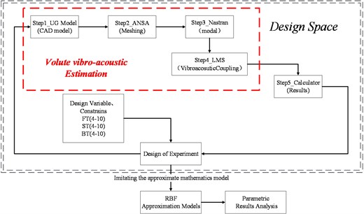
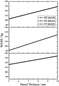
Fig. 15 shows the main effect profile of the Kirchhoff SPW and the total mass of the volute. It can be seen from the figure that the BT, ST and FT have the best reasonable range resulting in the vibrational sound radiation of the volute surface to be at a minimum.
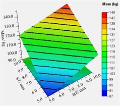
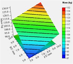
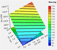
In addition, Fig. 15(b) revealed that the thicker the thickness of the volute panel, the greater the value of total mass. To analyze the relationship between different variable combinations and approximate model responses, the relationship between different combinations of volute panel thickness and the Kirchhoff SPW and mass of volute is shown in Fig. 16. Regarding the Kirchhoff SPW shown in Fig. 16(a)-(c), the FT-ST and BT-ST combinations present similar distribution characteristics. Therefore, the Kirchhoff SPW basically remained a constant smaller value when the ST was greater than 7.0 mm, and the BT was less than 8.5 mm or the FT was less than 7.0 mm. In addition, as the FT is smaller and the BT is larger, the Kirchhoff SPW is observed to have a smaller value as shown in Fig. 16(b). The aforementioned analysis shows that the variation in ST is the most sensitive to the sound radiation power of the volute structure surface, FT is second, and BT is the least. Therefore, it is possible to obtain a smaller Kirchhoff SPW value by increasing the ST value and decreasing the FT and BT values. Concerning the total mass of the volute, it can be concluded from Fig. 16(d)-(f) that the total mass of the volute is proportional to the volute panel thickness, A smaller total mass volute can be obtained only when the ST, BT, and FT values are smaller.
According to the aforementioned results of parametric analysis, considering the minimum values of the radiated sound power and total mass of the volute obtained, a reasonable range of ST, BT and FT is ST ≤ 7.5 mm, BT ≤ 6.0 mm, and FT ≤ 6.0 mm.
Fig. 15The main effect profile of the Kirchhoff SPW and the total mass of the volute

a)
b)
Fig. 16The relationship between different combinations of volute panel thickness and the Kirchhoff SPW a)-c) and mass of volute d)-f)
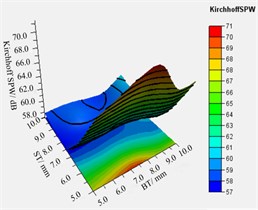
a) BT-ST
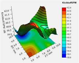
b) FT-BT
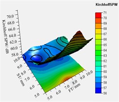
c) FT-ST
d) BT-ST
e) FT-BT
f) FT-ST
4. Conclusions
Concerning the fan system with the long pipelines connected on the inlet and outlet, the structural vibration noise is the main component of the external radiated noise, and is caused by the volute vibration which is excited by the unsteady aerodynamic force on the volute casing. The volute vibrational noise radiation was reduced based on vibro-acoustic optimization. The parametric analysis presented in this paper is fundamental research for volute vibrational noise optimization, providing a basic database and scope of variables for optimization. The main conclusions obtained are as follows:
1) In this paper, a method of numerical calculation of unidirectional coupling of fluid-structure-sound was implemented, and the rationality of this method was verified by dynamic pressure measurement and vibration measurement of the volute casing.
2) The normal vibration of the volute was the decisive factor that determined the volute surface acoustic radiation. The mechanism of the generated volute vibration noise can be summarized as follows: the unsteady aerodynamic force induced by unsteady flow at the outlet of the impeller of the fan excites the volute vibration, which results in the slight deformation of the volute casing surface, which then excites the vibrational sound radiation of the volute casing surface.
3) In this study, volute panel thickness (ST, BT, and FT) were taken as the design variables, and the radiated sound power of the volute surface was taken as the target function. The author established a parametric analysis method to obtain the designing space, which was used to construct an RBF approximation model to carry out parametric analysis. The parametric analysis results showed that increasing the ST value reasonably and decreasing the FT and BT values can result in a smaller Kirchhoff SPW value. The relationship between the total mass and volute panel thickness is a clear linear increase; the thicker the volute, the larger the total mass. At last, considering the minimum values of the radiated sound power and total mass of the volute obtained the reasonable range of ST, BT, and FT as follows: ST ≤ 7.5 mm, BT ≤ 6.0 mm, and FT ≤ 6.0 mm.
References
-
Koopmann G. H., Cunefare K. A., Neise W. Fan casing noise radiation. Journal of Vibration and Acoustics, Vol. 113, Issue 1, 1991, p. 37-42.
-
Hwang Won-Gul, Oh Il -Kwon, Kim Byounggun, Park Sungwoo, Ryu Kio A study on noise radiation from compressor shell. International Compressor Engineering Conference, Purdue, 2006.
-
Cai Jiancheng, Qi Datong, Lu Fu-an Numerical studys on fan casing vibration and noise radiation. Proceedings of ASME Turbo Expo, Orlando, USA, 2009.
-
Cai J. C., Qi D. T. A quantitative study of the blade passing frequency noise fan. Journal of Vibration Engineering, Vol. 14, Issue 3, 2012, p. 1200-1211.
-
Johnson M. E., Elliott S. J. Active control of sound radiation using volume velocity cancellation. The Journal of the Acoustical Society of America, Vol. 98, Issue 4, 1995, p. 2174-2186.
-
Li Shen, Zhao De-you Research on modal analysis of structural acoustic radiation using structural vibration modes and acoustic radiation modes. ACTA Acustica, Vol. 29, Issue 3, 2004, p. 200-208.
-
Chen Luyuan, Wang Deyu Ructural-acoustic optimization of stiffened panels based on a genetic algorithm. Journal of Marine Science and Application, Vol. 6, Issue 4, 2007, p. 55-61.
-
Zhang Jun, Zhao Wenzhong, Xie Suming Acoustic design optimization for coupled acoustic-structural systems. Journal of Vibration Engineering, Vol. 18, Issue 4, 2005, p. 519-523.
-
Yuksel Erdem, Kamci Gulsen, Basdogan Ipek Vibro-acoustic design optimization study to improve the sound pressure level inside the passenger cabin. Journal of Vibration and Acoustics, Vol. 134, Issue 6, 2012, p. 67-75.
-
Zhang Jianhua, Chu Wuli, Zhang Haoguang Numerical and experimental investigations of the unsteady aerodynamics and aero-acoustics characteristics of a backward curved blade centrifugal fan. Applied Acoustics, Vol. 110, 2016, p. 256-267.
-
Zhang Jian-hua, Chu Wu-li, Dong Xing-jie Numerical investigation of internal fluid-induced volute vibration in a marine centrifugal fan. Mechanical Science and Technology for Aerospace Engineering, Vol. 35, Issue 4, 2016, p. 523-530.
-
Koopmann G. H., Fahnline J. B. Designing Quiet Structures – a Sound Power Minimization Approach. Academic Press, 1997.
About this article

The authors would like to acknowledge the financial supports given by National Natural Science Foundation of China (No.51236006) and Natural Science Basic Research Plan in Shaanxi Province of China (Program No. 2016JQ1043).
