Abstract
Noncontacting torquemeters calibration is one of the acute tasks currently. Such sensors are widely used in measuring torques and torsional oscillations of elastic shafts of industrial plants and electromechanical systems. Noncontacting torquemeters must be properly calibrated before they are used to measure torque and torsional oscillations of rotating shafts. The paper describes a new approach to solving the task of calibration of noncontacting torquemeters and torsional oscillations meters of elastic shafts. The approach is based on the finite elements method as well as realized in the measuring device – torquemeter. The torquemeter allows to measure little torques and torsional oscillations of elastic shafts of electromechanical complexes.
1. Introduction
Diagnostic systems are widely used to determine the dynamic state of rotating electrical machines. Vibration diagnosis systems have an important place among such systems [1, 2]. Vibration diagnostics systems comprise noncontacting torquemeters of rotating shafts of electromechanical complexes. Identification of attributes is one of the most time-consuming tasks in their development of vibration diagnostics systems. These attributes determine the intervals of good or fault state of the machine. This task solution is connected to measuring torques and torsional oscillations on elastic rotating shafts of electromechanical complexes [3-5]. Elastic shafts torsional oscillations appear at a sudden change of the torque applied to the shaft, e.g. at a sudden start or cutoff of the shaft rotating engine. Elastic shafts torsional oscillations measurement is based on torsional deformation measurement method by low-frequency triangular or saw-tooth voltages. This voltage is measure at high-voltage amplifiers (HVA) outputs during the action period of rotating shaft torsional deformation. Then HVA determine their delay [3, 6-8].
2. Measuring rotating shafts torsional deformation by symmetrical saw-tooth law of HVA output voltages
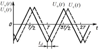
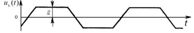
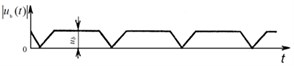
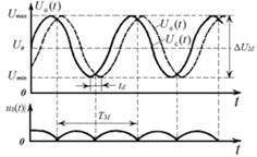
Symmetrical saw-tooth law of HVA output voltages (Fig. 1(a), (b)) is used in the torquemeter to measure rotating shafts torsional deformation [1, 3, 4, 6, 7]. HVA determines the largest deviation of symmetric triangular voltage (Fig. 1(a), (b)). High-voltage differential amplifier (HVDA) is also used for defining out from HVA in-phase high saw-tooth output voltages their differential voltage (Fig. 1(b)). Differential voltage appears as a result of delay between HVA high voltages emerging at load action on the shaft [3] (Fig. 1(a), (b)). Assuming the reference signal voltage HVAо changes according to linear law, then the shifted signal voltage change HVAс will delay for the time , where – the shaft torsional angle at torsional deformation; – circular frequency of shaft rotation [1, 3, 6]. Differential beat voltage (Fig. 1(b)) is formed mixing these saw-tooth output voltages.
Voltage increment value of reference HVAо (differential voltage) is easily determined from (Fig. 1(b)) and is equal to:
i.e. proportional to the shaft torsional angle from torsional deformation [1, 3, 6]. In (1) – HVA symmetrical triangular voltages delay time, – circular frequency of shaft rotation, – shaft torsional angle at torsional deformation.
The shaft torsional angle or, otherwise, the shaft two sections angle of relative rotation, disposed at distance one from another, under the action of torque is expressed by:
where – shaft material shear modulus; – shaft section polar moment, – shaft torque.
Maximum shaft sensing element (SE) torsional angle is limited by the allowable value of transverse strain in measuring shaft SE outer layers, expressed by:
where – measuring shaft diameter.
From Eq. (1)-(3) can be expressed:
i.e. differential beat voltage is proportional to the shaft period of rotation or the reference HVA high voltage period and transverse strains on the shaft SE outer layers.
Fig. 1Symmetrical saw-tooth law of: a) HVA high voltage change, b) differential voltage at HVA voltage ramp
a)
b)
3. Structural flow chart of torsional deformation meter by differential beat voltage
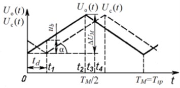
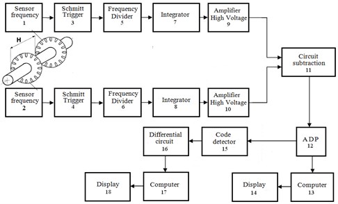
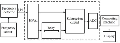
The structural flow chart of torque and torsional oscillations measuring device of rotating elastic shaft is shown in Fig. 2 [1, 3, 4, 6]. Reference HVAо high voltage comes on input 1 of HVDA circuit. Shifted high voltage from HVAс comes on input 2 of HVDA circuit and delays for the time relative to HVAо high voltage (Fig. 3(а)). As a result of subtraction of two output HVA high voltages on HVDA circuit input appears differential beat voltage (Fig. 3(c)). Instantaneous differential beat voltage equals an absolute value of instantaneous values difference of reference and shifted HVA output high voltages [1, 3, 4, 6]:
though formally the sign of beat voltage can be taken into account [1, 3, 4, 6]. In Eq. (5) – HVAс shifted signal voltage.
Fig. 2Structural flow chart of torquemeter and torsional oscillations meter of elastic shaft by differential beat voltage
The above said is shown in (Fig. 3(b), (c)). Instantaneous differential beat voltage, which is constant through most of the modulation period , is a basic one.
Then, the basic differential beat voltage taking into account Eq. (4) equals:
where – output voltages deviation; – modulation frequency. Usually of high voltage amplifiers can up to 200 V, and – dozens of Hz.
After subtracting reference and shifted instantaneous HVA output high voltages in HVDA circuit, at its input instantaneous differential beat voltage is singled out, coming on the input of analogue-to-digital converter (ADC). ADC transforms instantaneous differential beat voltage into digital beat code .
Fig. 3Time charts of processes inside torquemeter and torsional oscillations measuring device of elastic shaft by differential beat voltage
4. Realization of torsional deformation meter by differential beat voltage
Photoelectric (or inductive) sensors 1 and 2 shaft speeds (Fig. 2) are installed along the shaft. These sensors produce two phase-shifted signals with a frequency proportional to the frequency of rotation of the shaft.
The elastic shaft torquemeter consisting reference and shifted HVA high voltages and singling out differential beat voltage and digital beat code (Fig. 2), comprises sensors 1 and 2 of the shaft speed, placed on the borders of the shaft measuring area. Sensors outputs 1 and 2 are connected by Schmitt trigger circuits 3 and 4 and frequency dividers 5 and 6 to integrators inputs 7 and 8, which in their turn are equipped at the output with high voltage amplifiers HVAо 9 and HVAс 10. The latter outputs are connected to subtract circuit inputs (high voltage differential amplifier HVDA 11, ADC 12 mounted on its output, its output connected to the input of digital beat code calculator 13 (computing machine) and indicator 14 [3, 6]. Code detector 15, differentiating circuit 16, computing machine 17 and indicator 18 are introduced into the structural flowchart of torque measurement (Fig. 2) for singling out elastic shaft torsional oscillations, their measurement and assessment.
5. The task of rotating shafts noncontacting torquemeters calibration on the finite elements method
Rotating shafts noncontacting torquemeters calibration is primarily based on assessment of shear deformation along elastic SE section of their measuring shafts (round torsion bars), when variable torques are applied to them.
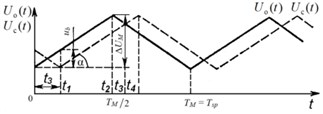
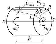
Assuming the shaft rotates at an angular frequency , and when rotating affected by torques and torsional oscillations of frequency appears. The torques and are created by elastic strains, inertia moments or external moments relative to measuring shaft SE – elastic torsion bar, its form of section unchanged. In this case only elastic torsion bar angle deflection takes place. Values of measuring shaft SE elements torsion do not remain constant and equal to , but change at linear velocity , where – is shaft radius [9]. Thus, function depends only on coordinate and does not depend on coordinates and (Fig. 4).
Fig. 4Time charts of processes inside torquemeter and torsional oscillations measuring device of elastic shaft by differential beat voltage
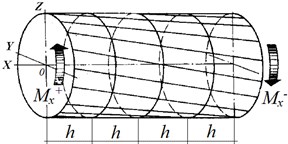
The task of rotating shafts torquemeter calibration is to measure displacements in time at all measuring shaft SE points. For this purpose discretization along coordinate and time for measuring shaft SE is introduced. Following this, the mesh steps are numbered [9].
Next, an arbitrary element numbered as of measuring shaft round torsion bar is selected and its dynamic equilibrium equation is written in the form of:
where – is an element inertia forces moment (element inertia moment).
Torques are determined through transverse strains [9, 10]:
where – is the distance from the area element to the measuring shaft SE (radius) centre (Fig. 4).
Transverse strains change over surface both by value and direction. Transverse strains are proportional to :
where – shear modulus of measuring shaft SE material.
Now the expression for the torque can be written in the following form:
Eventually the equilibrium equation acquires the following form [9, 10]:
This equation introducing discretization not only by coordinate , but also by time , where – time step number, – time step in time. The inertia moment is proportional to the torsion bar section inertia polar moment , where – is measuring shaft material density.
Length elements and time values , determining discretization by coordinate and by time are physical constants for elastic measuring shaft SE, i.e. constants and [11]. In this case torsion time is determined by [11]:
These Eqs. (12), (13) for mesh step in time and torsion bar torsion time are used to calibrate noncontacting torquemeters of rotating shafts.
Mechanical oscillations propagation speed in solid bodies is determined by:
where – elastic modulus, – shaft material density, – Poisson’s ratio.
Then maximum deformations in all the shaft SE elements turn out to be the same and equal [9]:
Calibration is carried out as follows: basing on the expressions for mesh step in time and torsion bar torsion time, a calibration circuit is introduced into rotating shafts noncontacting torquemeters in which mesh step in time and torsion bar torsion time are replaced by delay time in the delay line in measuring calibration circuit (Fig. 5).
Fig. 5Measuring calibration circuit, integrated in rotating shafts noncontacting torquemeters
Rotating shafts noncontacting torquemeters calibration is based on the use of measuring system, comprising reference high voltage amplifier HVAо, its voltage changing by sinusoidal harmonic law, delay line, HVDA voltage subtraction circuit, analogue-to-digital converter ADC, computing machine and indicator.
Preserving the phase shift shaped harmonic signals (Fig. 5(b)) from HVAо and from the delay line are transmitted to the voltage subtraction circuit. ADC (Fig. 5(a)) is linked up with the voltage subtraction circuit output, connected to the computing machine input. The computing machine calculates digital beat code , coming from ADC output, which is proportional to the resulting shear deformations under the effect of torsional moments and [3, 4, 6]. Following this, the beat code comes on the indicator input.
The computing machine transforms the beat code into the elastic shaft torsional deformations values. The output computation of elastic shaft torsional deformation in shaft torsion angular units or in torsional moments values is displayed by digital indicator [3-6].
6. Conclusions
A new approach of rotating shafts noncontacting torquemeters calibration is used in the article, based on new technical solutions and methods. It has been realized by phase shift meter and differential digital beat code with reference high voltage amplifier. The presented new method of noncontacting torquemeters calibration can be practically applied when measuring and controlling torsional moments, and when diagnosing and assessing the remaining operation life of energy consuming machines working shafts – presses, compressors, NPP pumps on a real-time basis.
References
-
Caronti A., Majjad H., Ballandras S., Caliano G., Carotenuto R., Iula A., Foglietti V., Pappalardo M. Vibration maps of capacitive micromachined ultrasonic transducers by laser interferometry. IEEE Transactions on Ultrasonics, Ferroelectrics, and Frequency Control, Vol. 49, Issue 3, 2002, p. 289-292.
-
Pieczonka L., Klepka A., Martowicz A. Nonlinear vibroacoustic wave modulations for structural damage detection: an overview. Optical Engineering, Vol. 55, Issue 1, 2016, p. 011005.
-
Gordeev B. A., Okhulkov S. N., Plekhov A. S., Bugaisky V. V., Gorskov V. P. Measuring the torque of rotating shafts. Russian Engineering Research, Vol. 35, Issue 5, 2015, p. 315-319.
-
Taradai D. V., Deomidova Y. A., Zile A. Z., Tomashevskii S. B. Results from investigations of torsional vibration in turbine set shaft systems. Thermal Engineering, Vol. 65, Issue 1, 2018, p. 17-26.
-
Lu X., Zhang J., Ma L., Lin J., Wang J., Wang J., Dai H. Effects of misalignment on the nonlinear dynamics of a two-shaft rotor-bearing-gear coupling system with rub-impact fault. Journal of Vibroengineering, Vol. 19, Issue 8, 2017, p. 5960-5977.
-
Okhulkov S. N. Patent for Invention. the Way to Determine Torque, No. 2196309 dated 10.01.2003, upon request No. 2000110472 dated 24.04.2004.
-
Gordeev B. А., Okhulkov S. N., Osmekhin A. N., Shohin А. Е. Reducing transient vibrations due to rotating shafts. Russian Engineering Research, Vol. 38, Issue 5, 2018, p. 335-341.
-
Stoisser C. M., Audebert S. A comprehensive theoretical, numerical and experimental approach for crack detection in power plant rotating machinery. Mechanical Systems and Signal Processing, Vol. 22, 4, p. 818-844.
-
Giniotis V., Bručas D., Petroškevičius P., Kuzas P. Mechatronic structure of modern test bench for precise angle calibration. Journal of Vibroengineering, Vol. 10, Issue 1, 2008, p. 65-68.
-
Scott R. L. Numerical Analysis. University of Chicago, Chicago, 2011.
-
Kim J. S., Kim G.-W. New non-contacting torque sensor based on the mechanoluminescence of ZnS:Cu microparticles. Sensors and Actuators, A: Physical, Vol. 218, 2014, p. 125-131.
-
Schicker R., Wegener G. Measuring Torque Correctly. Hottinger Baldwin Messtechnik GmbH, Darmstadt, 2002.
-
Valenzuela M. A., Bentley J. M., Lorenz R. D. Evaluation of torsional oscillations in paper machine sections. IEEE Transactions on Industry Applications, Vol. 41, Issue 2, 2005, p. 493-501.
About this article

The work has been carried out at the expense of the Russian Foundation for Basic Research No. 18-48-520010-р_а.
