Abstract
This article considered method to measure low-frequency angular oscillations of rotors of electric machines and solved the problem of assess shear deformations of rotating shafts in transient conditions. Method of calculating torsional torques is considered by the example of electric generator shaft of diesel generator unit. This method allows taking into account the angular deformations of the rotating shafts, and reducing vibration overloads, and increasing in both resource and reliability.
1. Introduction
Control over rotating electrical machines dynamic state according to the engineering status is carried out by various engineering systems. Vibration diagnostics systems are most important among them [1-6]. The development of such systems is a difficult task, since should be determine the parameters that can estimate the machine state. In addition, it should establish their values, which determine the intervals of a good or fault state of the machine [5, 7, 8]. Finite elements method is used to solve this task [6, 9-12].
2. Requirements to calculate deformations of electrical machines rotating actual shafts
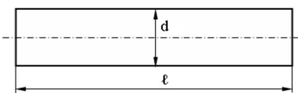
Variable section shafts are often found at the calculations torsional oscillations of the electric machines shafts [13-16]. Often the section of the shaft changes in step from one diameter to another (Fig. 1). In Fig. 1 shows the shaft of an asynchronous motor 4AK250.
Fig. 1Sketch of motor shaft
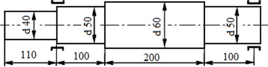
In actual shafts structures at the junctions of shaft areas of different length and diameter there are fillets-corner round-offs at the parts. For such junctions it is necessary to apply the method of determination the equivalent shaft area [9-13].
It is difficult to choose equations for the description of shaft oscillations in the analytical solution of the task, since should be take into account both the general requirements for the initial and boundary conditions and the requirements for intermediate boundary conditions at the shafts junctions [14-17]. These requirements are called join of solution by intermediate end conditions. Using join of solution presents a considerable difficulty at searching for analytical solutions [9, 10, 12].
The use of a difference equation to solve a problem avoids the join of solution, but in this case should be add an additional equation of motion for the junction element of shafts [12]. Torsional oscillations for shafts areas of smaller and bigger diameters can be expressed by differential equation:
where – shear modulus of shaft material, – shaft material density, – actual shaft angle of rotation. Eq. (1) can be written in a difference form:
where – is an element inertia forces moment (element inertia moment), – actual shaft element polar moment, – mesh step along the actual shaft length.
Dynamic equation for real shaft joint can be expressed:
where and – refer to different shaft areas of different diameters.
The center shaft area of the intermediate element-mesh point is placed at the boundary [12] (Fig. 2(a)).
Fig. 2The center of the: a) shaft area intermediate element-mesh point is placed on the boundary, b) cross-section cut of a shaft in cylindrical coordinate system
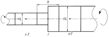
a)
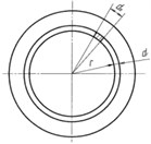
b)
Then instead of Eq. (2) it is necessary to write:
Shortcut in this case is not possible and it is necessary to calculate both central inertia moments and inertia forces moment – . For example:
In the case of circular section shafts, evaluation of integrals in Eq. (5) is not difficult if cylindrical coordinate system is used (Fig. 2(b)), where – is shaft radius.
For example, and:
The equation is obtained by substituting numerical values into Eq. (4) [12]. Choose an element of constant section with 1 as the final element for determining the parameters of the shaft.
3. Determining the reduced shaft length and diameter
Reduced and transmission shafts of electromechanical complexes, travel mechanisms of mobile machines usually have stepped configuration which considerably complicates the task of determining numerical value of torsional rigidity of shaft lines shafts [13-15]. To determine the numerical value of the torsional stiffness of the shaft of a step configuration, it is advisable to substitute the stepped shaft (Fig. 3(a)) with a smooth shaft of equivalent rigidity [13] (Fig. 3(b)).
Now total length of the shaft will be called reduced length . The diameter shaft is constant through the full length. Now it will be called the reduced diameter . The shaft length and diameter are the shaft primary geometrical dimensions to determine torsional rigidity numerical value [13, 14, 16].
Fig. 3a) Actual, b) reduced shafts drafts
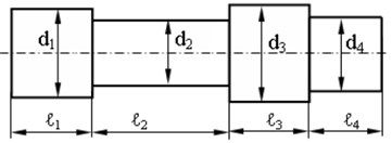
a)
b)
The reduced shaft diameter can be determined by:
where – reduced shaft length, – reduced shaft diameter.
The stepped shaft can be considered as discreet bodies connected in series having respective diameters and length. This shaft compliance is determined by summing up shaft areas compliances .
Shaft torsional rigidity is its inverse compliance value , it can be:
The shaft torsional rigidity consists of the torsional rigidity of each shaft section:
From (9) obtain an equation for the shaft reduced length:
Thus, it is possible to calculate the parameters for the dynamic model of the object under study, using such notions as the shaft reduced length and the shaft reduced diameter.
4. Calculating maximum deformations of the electric generator rotor reduced shaft of diesel generator unit
The finite element method [9, 11] is used to estimate the maximum shear deformations of electric generator rotating shaft of unified electric power plants (UEPP) standalone object, caused by torsional torques.
The diesel crankshaft of diesel generator units (DGU) UEPP connected to the rotor of a synchronous electric generator through a plate coupling, absorbing axial, radial and angular displacements with the lowest reaction forces due to its elastic and dissipative properties [10].
The method for estimating rotating shafts maximum shear deformations is described below.
According to the expression 1 time step [9, 11, 12]:
Mechanical oscillations propagation speed in solid bodies is determined by:
where – elastic modulus, – Poisson’s ratio.
The shaft SE torsion time ratio [9, 10, 12]:
where – measuring reduced shaft length, – mechanical oscillations propagation speed, – reduced shaft torsion time.
This time does not depend on the torsion velocity of the shaft SE , on the steps selected and .
Maximum deformations in all the shaft SE elements turn out to be the same and equal [9, 10, 12]:
For example, the linear velocity of the shaft elements torsion is equal 162.65·10-3 m/s for the reduced rotor shaft of DGU electric generator at torsional oscillations frequency 6.28 rad/s and the shaft radius 0.0259 m. The electric generator rotor shaft material has the following characteristics: shear modulus 8∙1010 n/m²; 7,8∙103 kg/m3, and the mesh step is selected as equal to 0,0651 m, then according Eq. (11) the time step becomes equal 20.327·10-6 s. The electric generator rotor shaft elements are in torsion at the velocity of 325.3·10-3 m/s, then from Eq. (14) obtain maximum deformations in all rotor shaft elements equal [9, 10] 50.7875·10-6.
Thus, maximum deformations in all rotor shaft elements turn out to be small. Therefore, every unit for the rotor shaft elements equals 50,787 microns. Maximum strains in all electric generator shaft elements turn out to be equal [9, 10] 4063∙103 N/m2.
The maximum reciprocal turn of sections of all elements on the electric generator rotor shaft relative to each other is found by:
Use the following example data: 50.7875·10-6; 0.0259 m; 0,0651 m, then the maximum reciprocal turn of sections of all elements on the electric generator rotor shaft relative to each other is a value 1276.55·10-6 rad.
Maximum deformation of the electric generator rotor shaft of the length 0.651 m transform to angular units 242.68” = 4.04’ – angular seconds and angular minutes respectively [9, 10].
Maximum time of electric generator rotor shaft torsion of the length 0.651 m, at 6.28 rad/s and 1.0 s will represent a value 203.169·10-6 s.
The admissible torque rating on the electric generator rotor shaft is determined by:
Integral in Eq. (16) is a polar moment of inertia of electric generator rotor shaft, of radius . Electric generator rotor shaft of a uniform section has a polar moment of inertia which is constant along the shaft length and does not depend on the length of its base area 0.651 m:
Polar moment of inertia is determined expression for the electric generator rotor shaft section of radius 0.0259 m the [12]. Initial conditions of this task are as follows:
– Shear modulus of the electric generator rotor shaft 8∙1010 N/m2.
– Electric generator rotor shaft material density 7.8∙103 kg/m3.
– Rigidity.
Then:
The torque is determined from Eq. (16). Torque is 110.883 Nm for the electric generator rotor shaft at torsional oscillations frequency 6.28 rad/s.
The irregularity in crankshaft rotational frequency reaches 0.7 % for DGU with an 8-cylinder diesel engine. The engine runs calmer at lower irregularities. Torsional oscillations cyclic frequency is 5.0 Hz, or circular frequency is 31.4 rad/s at the irregularity in crankshaft rotational frequency being 0.7 % [10].
The torque equals 15.968∙103 Nm at torsional oscillations frequency of DGU crankshaft 5.0 Hz from torsional oscillations at end areas (elements) of the crankshaft.
Torque from the crankshaft DGU on the shaft of the electric generator affects the strength of the rotor shaft. This increases the eccentricity of the rotor shaft and vibration, if the crankshaft DGU directly connected to the rotor shaft of the generator [3, 10].
The shaft of the electric generator is connected to the crankshaft of a diesel engine DGU through a plate coupling. In this case, the electric generator rotor shaft operates within the rotational frequency operational range without losing the strength. This ensures smoothness of shaft rotation of the generator and ensures safe operation in the UEPP.
5. Conclusions
The method allows calculating the maximum deformations actual rotating rotor shafts of UEPP generators of standalone objects. The real shafts of actual structures of traction generators rotor have fillets at the junction points of the shaft sections of different diameters. These fillets increase the strength of the shaft and reduce internal stresses. Therefore, the real shafts need to be converted to an equivalent shaft of circular cross section.
References
-
Thorby D. Structural Dynamics and Vibration in Practice: an Engineering Handbook. Butterworth-Heinemann, Oxford, 2008.
-
Blekhman I. I. Vibrational Mechanics: Nonlinear Dynamic Effects, General Approach, Applications. World Scientific, Singapore, 2000.
-
Thompson D. Railway Noise and Vibration: Mechanisms, Modelling and Means of Control. Elsevier, Oxford, 2009.
-
Bialas K. Mechanical and electrical elements in reduction of vibrations. Journal of Vibroengineering, Vol. 14, Issue 1, 2012, p. 123-128.
-
Zhou W., Wei X., Zhai L., Wei X., Wang L. Nonlinear characteristics and stability optimization of rotor-seal-bearing system. Journal of Vibroengineering, Vol. 16, Issue 2, 2014, p. 818-831.
-
Feng N. S., Hahn E. J., Randall R. B. Simulation of Vibration Signals from a Rolling Element Bearing Defect (DSTO-GD-0262). University of New South Wales, Sydney, 2004.
-
Gordeev B. A., Kovrigin D. А., Leontyeva А. V. Rotor synchronization of two motors on an elastic base. Russian Engineering Research, Vol. 31, 2011, p. 923-927.
-
Jauregui J. C. Parameter Identification and Monitoring of Mechanical Systems under Nonlinear Vibration. Elsevier, Cambridge, 2014.
-
Gordeev B. A., Okhulkov S. N., Osmehin А. N., Shohin А. Е. Reducing transient vibrations due to rotating shafts. Russian Engineering Research, Vol. 38, Issue 5, 2018, p. 335-341.
-
Gordeev B. А., Okhulkov S. N., Osmehin А. N., Korendyasev G. K. Assessment of elastic and damping characteristics of rotating shafts magnetorheological box-coupling. Vestnik Mashinostroeniya, Vol. 5, 2018, p. 9-13.
-
Nippes P. I. Early warning of developing problems in rotating machinery as provided by monitoring shaft voltages and grounding currents. IEEE Transactions on Energy Conversion, Vol. 19, Issue 2, 2004, p. 340-345.
-
Matsushita O., Tanaka M., Kanki H., Kobayashi M., Keohg P. Vibrations of Rotating Machinery: Volume 1. Basic Rotordynamics: Introduction to Practical Vibration Analysis. Springer Japan, Tokyo, 2017.
-
Lu C., Wang Y., Ragulskis M., Cheng Y. Fault diagnosis for rotating machinery: A method based on image processing. OLoS ONE, Vol. 11, Issue 10, 2016, p. e0164111.
-
Astashev V. K., Babitsky V. I., Kolovsky M. Z. Dynamics and Control of Machines. Springer, Berlin, 2000.
-
Friswell M. I., Penny J. E. T., Garvey S. D., Lees A. W. Dynamics of Rotating Machines. Cambridge University Press, Cambridge, 2015.
-
Wittenburg J. Dynamics of Multibody Systems. Springer, Berlin, 2008.
-
Goroshko A., Royzman V., Zembytska M. Quality and Reliability of Technical Systems: Theory and Practice. JVE International, 2018.
About this article

The research work has been carried out at the expense of a Russian Science Foundation Grant (Project No. 15-19-10026).
