Abstract
In order to analyze the effect of abrasive concentration on the quality of abrasive flow machining, this paper takes the baffle servo valve as the research object and carries out numerical analysis of solid-liquid two-phase abrasive flow machining process. By analyzing the static pressure and velocity fields of nozzle orifices in baffle servo valves under different abrasive concentration conditions, it is found that abrasive flow has the best precision machining effect when the abrasive concentration is 10 %. And the best quality area for abrasive flow machining is in the small hole. The study shows that the larger the abrasive concentration is, the better the quality of abrasive flow machining is.
1. Introduction
At present, the development of science and technology is more and more rapid, and the method of mechanical processing is also developing rapidly with the progress of the times, gradually from the former rough processing to the direction of precision and ultra-precision. Abrasive flow is a kind of viscous non-Newtonian fluid, which is composed of polymer carriers, abrasive particles and additives. The processing method of the abrasive flow is to have a set of hydraulic cylinders and abrasive cylinders in the upper and lower parts. During the processing, the semi-solid abrasive in the inner cavity is used to force the flow through the processed surface under the repeated action of the upper and lower cylinders, the surface to be processed is continuously pressed by the abrasive flow containing abrasive grains to achieve the purpose of finishing the surface of various cavity surfaces [1-3].
The principle of abrasive flow machining is to use the abrasive particles in the abrasive flow as millions of cutting tools (self-sharpening), with its hard and sharp edges and corners to repeatedly cut the surface of the workpiece, to deburr, polish and chamfer the workpiece [4-6]. At present, abrasive flow technology is developing rapidly. Many excellent scholars study abrasive flow from some new perspectives, such as interpreting abrasive flow from the perspective of molecular dynamics, simulating abrasive flow processing in a coupled way, and so on [7, 8].
Because the size of the nozzle of the baffle servo valve is small, and its processing precision is very high, especially the small hole in the nozzle, when the inner wall of the small hole of the nozzle retains burrs or is not smooth enough, the nozzle will be scattered or blocked, which will affect the overall performance and service life of the servo valve, therefore, precise polishing of nozzle orifices to achieve the required accuracy and improve the surface quality of orifices is of great research significance [9, 10].
2. Geometric model and boundary condition settings
In this paper, the nozzle of the flapper servo valve is taken as the research object. According to the physical model of the flapper servo valve, the fluid region model in the channel of the flapper servo valve is constructed. The schematic diagram of the nozzle area is shown in Fig. 1. The length from the abrasive inlet to the abrasive outlet 1 was 4 mm, the inlet diameter was 1 mm, the outlet diameter 1 was Ø0.1 mm, and the length from the outlet 2 to the outlet 3 was 2 mm and the diameter was Ø0.5 mm.
Fig. 1Schematic diagram of nozzle area division
Before applying the fluid dynamics software FLUENT for numerical analysis of abrasive flow research, it is necessary to set the relevant flow field parameters, and the parameter settings are combined with the actual processing conditions. In this paper, the inlet boundary setting is adopted, and the mixed model of solid-liquid two-phase flow is adopted, and the Mixture model is selected in Models. During the actual machining process, the workpiece is at rest and there is no translational phenomenon on the wall, so the wall slip option is removed and the Energy Equation is activated in the energy model. Set the exit condition to free exit, because the pressure and speed of the outlet cannot be accurately predicted during the actual processing of the abrasive flow. This setting makes the numerical simulation more realistic. The hexahedral mesh quality is more complex than the generation process and is mainly suitable for geometries with higher requirements on the mesh. Therefore, this paper mainly uses the topological block structure to mesh the hexahedron on the flapper servo valve nozzle.
3. Analysis of influence of abrasive flow on nozzle small hole grinding and polishing under different abrasive concentrations
3.1. Analysis of influence of different abrasive concentrations on static pressure of nozzle holes
The value of the abrasive flow under different abrasive concentrations was analyzed for the baffle servo valve. The initial setting was to select the abrasive grain size of 800 mesh and the initial velocity of 40 m/s, and the abrasive concentration is 4 %, 6 %, 8 %, and 10 %, respectively, to simulate values, and obtain static pressure cloud images at different abrasive concentrations. Taking the static pressure with abrasive concentration of 10 % as an example, cloud chart analysis is carried out, as shown in Fig. 2.
According to the dynamic pressure cloud image of the nozzle shown in Fig. 2 when the abrasive concentration is 10 %, it can be seen that the static pressure of the nozzle is maximum in the large part of the hole. After the abrasive enters the small hole, the static pressure decreases and keeps stable. The change of the nozzle aperture affects the static pressure value. The static pressure curve at the nozzle center line 1 is further analyzed. The nozzle center line 1 is shown in Fig. 1, and the static pressure curve of the nozzle under different abrasive concentration is shown in Fig. 3.
Fig. 2Numerical cloud map of the static pressure of the nozzle when the abrasive concentration is 10 %
Through the static pressure curves of different abrasive concentration shown in Fig. 3, it can be seen that when the abrasive has just entered the nozzle of the baffle servo valve, the static pressure keeps stable and the internal value of the nozzle remains unchanged. As the abrasive moves to the small hole, the static pressure value decreases rapidly, and it can be found that the higher the abrasive concentration, the larger the static pressure value. When the abrasive concentration is 10 %, the static pressure is obviously higher than that of the other three abrasive concentrations, which shows that the abrasive flow polishing effect is better when the abrasive concentration is 10 %.
Fig. 3Change of static pressure curve of nozzle under different abrasive concentration
3.2. Influence of different abrasive concentration on velocity field of nozzles
Through the static pressure numerical analysis under different abrasive concentration, the velocity field is analyzed. Fig. 4 shows the variation of the velocity field when the abrasive concentration is 10 %.
Fig. 4Numerical cloud map of velocity field of nozzle at an abrasive concentration of 10 %

Through the numerical cloud map of nozzle velocity field shown in Fig. 4 when the abrasive concentration is 10 %, it can be found that the velocity field has no obvious change at the big hole, and the change is obvious at the front and small hole of the cross hole. The abrasive movement is more free when the abrasive moves in the big hole. When the abrasive moves to the intersection, because the aperture becomes smaller and the abrasive gathers at the intersection, the velocity at the intersection becomes larger and the polishing effect becomes better. When the abrasive enters the small hole, the aperture decreases again and the velocity increases. In order to further analyze the change of velocity in nozzle under different abrasive concentration, the curve of velocity field of nozzle under different abrasive concentration is obtained as shown in Fig. 5.
Fig. 5Variation of large hole velocity field of nozzle under different abrasive concentration
Fig. 6Curves of velocity field of nozzle cross hole and small hole under different abrasive concentration
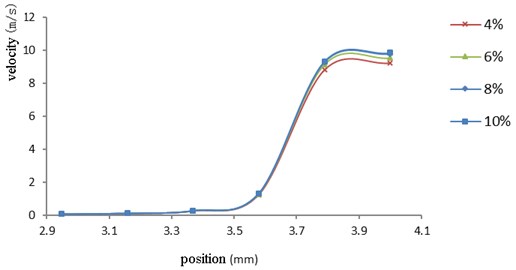
Fig. 5 is a curve change of a large hole velocity field, and Fig. 6 is a curve change diagram of a cross hole and a small hole velocity field. It can be seen from the graph that the velocity field at the same position under different abrasive concentrations does not change much. The velocity curve at the abrasive concentration of 10 % is slightly higher than that of the other three abrasive concentrations. With the movement of the abrasive, the velocity increases steadily upward, and increases significantly when the abrasive reaches the cross hole. After entering the small hole, the velocity of the abrasive keeps relatively stable until the outlet.
4. Conclusions
By analyzing the static pressure distribution under different abrasive concentration conditions, it is found that the static pressure of the large pores is the maximum and remains stable. When the pores enter the pores, the static pressure decreases. As the concentration of the abrasive grains increases, the static pressure also increases. When the concentration of the abrasive grains is 10 %, the static pressure value is the largest, and the grinding and polishing effect on the workpiece is the best.
By analyzing the distribution of the velocity field under different abrasive concentration conditions, it is found that the velocity field grows in a stable state with the movement of the abrasive at the large hole. When the abrasive moves to the intersection hole, the abrasive gathers at the intersection because the diameter of the abrasive becomes smaller, so that the speed at the intersection becomes larger, and the polishing effect becomes better. When the abrasive enters the small hole, the aperture becomes smaller again and the speed increases. After the abrasive enters the small hole, the speed remains relatively stable until the outlet, and the polishing effect of the abrasive flow is remarkable. When the abrasive concentration is 10 %, the overall velocity field is maximized, and the effect on the wall surface is stronger and the polishing quality is higher.
References
-
Ji Shiming, Ma Baoli, Tan Dapeng Numerical analysis of soft abrasive flow in structured restraint flow passage. Optics and Precision Engineering, Vol. 19, 2011, p. 2092-2099.
-
Ding Jinfu, Zhang Kehua, Xu Yongchao, et al. Abrasive flow uniform surface polishing method and experiment for cycloidal pump inner rotor. Journal of Drainage and Irrigation Machinery Engineering, Vol. 31, 2013, p. 598-604.
-
Li Junye, Zhang Hengfu, Wu Guiling, et al. Numerical simulation analysis of five-step variable-diameter pipe with solid-liquid two-phase abrasive flow polishing. IOP Conference Series: Materials Science and Engineering. Vol. 301, 2018, p. 012040.
-
Ji Shi Ming, Huang Xi Huan, Tan Dapeng, et al. Gas-liquid-solid three-phase abrasive flow finishing and optimization of its process parameters. Editorial Office of Optics and Precision Engineering, Vol. 24, 2016, p. 855-864.
-
Li Junye, Meng Wenqing, Zang Xiang, et al. Numerical simulation analysis of large eddy simulation for T-tube based on solid-liquid two-phase abrasive flow. Journal of Vibroengineering, Vol. 17, 2017, p. 142-146.
-
Liu Weina, Cai Zhijie, Li Yunfeng, et al. Numerical simulation and experiment of micro-hole abrasive flow polishing of fuel injector. China Mechanical Engineering, Vol. 28, 2017, p. 13-19.
-
Li Junye, Su Ningning, Hu Jinglei, Yang Zhaojun, Shengliang, Zhang Xinming Numerical analysis and experiment of abrasive flow micro-hole processing based on CFD-DEM coupling. Journal of Agricultural Engineering, Vol. 34, 2018, p. 80-88.
-
Li Junye, Meng Wenqing, Dong Kun, et al. Study of effect of impacting direction on abrasive nanometric cutting process with molecular dynamics. Nanoscale Research Letters, Vol. 13, 2018, p. 1-14.
-
Zhu Wendong Research on Servo Hole Small Hole Pairing Measurement System Based on Differential Pressure Flow and Pressure Characteristics. Ph.D. Thesis, China, 2016.
-
Hu Wengang Structural Shape and Flow Field Analysis and Modeling of the Jet Tube Servo Valve Receiving Hole. Ph.D. Thesis, China, 2016.
About this article

The authors would like to thank the National Natural Science Foundation of China No. NSFC 51206011, Jilin Province Science and Technology Development Program of Jilin Province No. 20160101270JC and No. 20170204064GX, Changchun Science and Technology Program of Changchun City No. 18DY017.
