Abstract
Marine propulsion shafting connects the main engine and propeller, and plays an important role in promoting the movement of ships. Along with the operation of shafting system, various vibration forms couple with each other and cause different kinds of coupled vibrations, which seriously threaten the safety and reliability of ships. In this paper, a finite element model of marine propulsion shafting is established with coupled constraint on the elements of propeller, and the coupled torsional and transverse vibration under idling and loading conditions are studied at different rotational speeds. According to comparison of numerical simulation results and experimental tests, the coupled finite element method can reveal the basic principles of coupled dynamics of marine propulsion shafting and provide good technical support for predicting the coupled vibration, thus improving the safety and reliability of sailing performance of the ships.
1. Introduction
The main engine acts as a heart part of the ships and plays an important role in the safety and reliability of vessel operation. In order to promote the operation of ships, the torque generated by main engine should be transmitted to propeller by virtue of the marine propulsion shafting, which is the connection between marine main engine and propeller [1]. During real navigation, the ships are usually perturbed by waves, wind and many other exciting forces in different forms, and all these excitations will lead to vibration response in the loading direction. As a result, coupled vibration responses may be excited in different directions simultaneously. Moreover, the pulsation of cycle work in marine main engine and the non-uniformity of propeller working area may cause extremely complex exciting force. These external and internal incentives coupled with each other and directly influence the reliability of marine propulsion shafting, which threatens the safety of ships seriously [2].
The marine shafting system suffers all kinds of exciting forces in actual operation. Each point on the shafting generates a response not only in the direction of disturbing force but also in other directions. The vibration forms of propulsion shafting includes torsional vibration, longitudinal vibration, transverse vibration and the coupled vibration of above vibration forms [3]. Common coupled vibration forms include coupled torsional-longitudinal vibration, coupled torsional-transverse vibration and coupled torsional-longitudinal-transverse vibration. When coupled vibration occurs, deformations and rotational angles will be produced [4].
Recently, some researchers have paid much attention to the three general vibration forms of marine propulsion shafting. For example, Warikoo R. used sufficiently accurate method to find the natural frequencies of transverse vibration of the propeller shaft [5]; Zhang G. B. used the finite element method to describe the dynamic behaviors of longitudinal vibration of marine propulsion shafting [6]. Besides, Yang Y. bulit vibration models for the vessel with transition matrix method for torsional vibration of shafting [7]. However, few studies have taken complex coupling vibrations into account.
Coupled vibration of propulsion shafting is a frontier topic in the field of ships in recent years [8]. Parsons M. G. started the research on coupled vibration, and concluded that the coupled vibration of propulsion shafting included inertia coupled vibration and damping coupled vibration [9]. Wu J. S. presented a computer programming technique using extended transfer matrix method to analyze the torsional-transverse coupled vibration of a damped shafting system with multiple degrees of freedom, and investigated its coupled dynamic behaviors under external excitations [10]. Jang M. O. used the energy method to calculate the stiffness matrix of crankshaft, and effectively predicted the complicated coupled torsional-longitudinal vibration of propulsion shafting system [11]. Murawski L. devised a computer program to analyze the coupling coefficients by nonlinear algorithms, and successfully determined the dynamic stiffness and damping characteristics [12]. Zou D. L. analyzed the steady-state response and the stabilities of coupled longitudinal-transverse dynamics of a marine propulsion shafting under super harmonic resonances [13]. Although these researches have studied the coupled vibration of propulsion shafting, few of them focus on coupled torsional-transverse vibration of marine propulsion shafting.
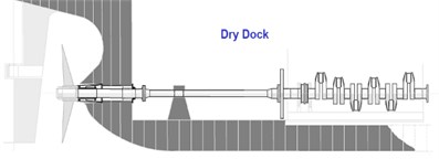
The vessels are particularly sensitive to hull deformation for its rigid shafting [14] and direct-coupled diesel engine installations. Hull deformation is the most important disturbance affecting bearing offsets, so that it is of great significance to consider hull deformation in the vibration study of propulsion shafting [15]. Chris L. from ABS reported in his research that the hull deformation had serious effects on the propulsion shafting [16]. Fig. 1 shows the comparison of propulsion shafting in dry dock and service. It can be seen that the shafting system deflects severely due to the hull deformation. As marine propulsion system is very sensitive to the change of loading conditions and hull deflection of the ship, hull deflection data can be obtained by comparing actual vertical positions of the bearings under several vessel loading conditions. This difference can represent the change extent of dry dock bearing positions under the influence of hull deflections [17]. However, it is very difficult to obtain these data of hull deflection in laboratory. Therefore, an applicable and accurate method of numerical simulation is needed to simulate the hull deformation.
Fig. 1The propulsion shafting in dry dock and service
In previous work, the FEA method has been demonstrated effective for dealing with coupled vibration of propulsion shafting [18]. In view of this, a finite element model with coupled constraint onto the propeller is proposed in this study, and then hull deformation is simulated by transverse loading on propulsion shafting experimental platform to validate the accuracy of this coupled FEA method. Firstly, the idling and loading vibration equations of coupled torsional-transverse are presented according to previous related theories. On this basis, the harmonic and transient analysis of marine propulsion shafting are carried out through experimental tests and numerical simulation. Further, the simulation results under transverse force are compared with those no force condition to analyze the effect of lateral force on performance, as well as the effect of hull deformation on marine propulsion shafting. At the same time, the corresponding experimental tests are performed to determine the accuracy of the coupled FEA method.
2. Equations of motion
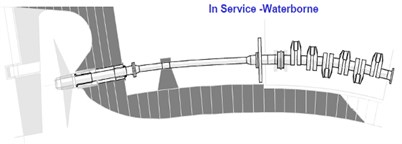
The propulsion shafting can be equivalent to a cantilever beam with a mass payload. Its mass center need not be coincident with the centerline of the beam [19]. The schematic of the beam with a mass point can be depicted as Fig. 2, in which denotes the length, denotes the cross-sectional area, denotes the second moment area about the bending axis. The , and denotes the density, the elastic modulus and the mass, respectively.
Fig. 2The schematic of the beam with a mass point
The beam may produce torsional vibration when rotating. Consequently, the shear stress and normal stress of cross section will change alternately, thus resulting in additional transverse vibration. Similarly, the beam may produce transverse vibration due to additional torsional vibration, so that the normal stress and shear stress will coexist. Then, the potential energy and kinetic energy of the beam can be expressed as follows respectively [20]:
where and denote the normal stress and the shear stress respectively; and denote the normal strain and the shear strain respectively; denote the function about time of transverse displacement and denote the torsional angle.
Supposing the external torque is and that the transverse force is . According to related theories of material mechanics, the extermal energy caused by torque and force can be respectively calculated by:
where and denote the shear modulus and the elastic modulus respectively; and denote the polar moment of inertia and the moment of inertia respectively; and denote the frequencies of external torque and transverse force respectively; and is the coordinate axis along the longitudinal direction.
In the following, a Lagrange function of time on the system deformation and another Lagrange function of time on the external force are established. According to the virtual displacement formula, the following equations can be obtained:
Based on the Hamilton principle , the above functions can be rewritten through subsection integral method as follows:
Thus, the coupled torsional and transverse vibration equations without external force of marine propulsion shafting can be determined as:
Since this paper focuses on the coupled motion equations of Euler beam, there is no need to consider the influences of shear deformation and moment of inertia, as well as the relationship between bending angle and shear stress. The coupled vibration equations may change due to the impact of external force. Supposing the transverse force is and that the external torque is zero, then the Lagrange function of time on the external force transforms into .
According to the above derivation steps, the coupled motion equations with transverse force can be writen as:
Eq. (6) is the vibration equations of coupled torsional-transverse Euler beam with transverse force, whcih is obviously different from that without force in Eq. (5). Therefore, the steady-state solutions of the coupled equations, namely the vibration form and amplitude of beam are totally different from those without force. Accordingly, the transverse deformation and torsional angle may change in certain aspects.
In order to study how hull deformation affects the coupled vibration of marine propulsion shafting, comparative analysis will be carried out thought numerical simulation and experimental test in the following.
3. Numerical simulation
Finite element analysis is universally recognized as the most important technological breakthrough in the field of structural engineering analysis. The FEA method is the only tool that yields satisfactory results for analyzing a complicated structure [21]. A coupled FEA method is proposed to analyze vibration of marine propulsion shafting. In order to ensure the accuracy of simulation results, the main material mechanical properties of the FEA model are consistent with those of experimental instruments.
In numerical simulation of marine propulsion shafting, the finite element model is established by SOLID45 unit. The element is defined by eight nodes, and each node has three degrees of freedom, namely translations in the , , and directions. All nodes possess capabilities of plastic deformation, creep deformation, swelling, stress stiffening, large deflection and large strain.
The propeller is simulated by MASS21 unit, which is a point element with six degrees of freedom, namely translations in the , , and directions and rotations around the , , and axes. Different mass and rotary inertia may be assigned to each coordinate direction. The material parameters of the MASS21 unit are equal to the force caused by flow field around the propeller.
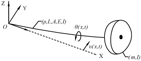
Fig. 3 shows the schematic of propulsion shafting experimental platform. The length of marine propulsion shafting is 9.6 m, of which the length of intermediate shaft 1 is 2.6 m, the length of intermediate shaft 2 is 2.0 m and the length of tail shaft is 5.0 m. The diameter of intermediate shaft 1 is about 0.14 to 0.16 m, the diameter of intermediate shaft 2 is about 0.12 to 0.16 m, and the diameter of tail shaft is about 0.11 to 0.14 m. The elastic modulus and shear modulus are 210 GPa and 77 GPa, respectively. The density is 7850 kg/m3 and the Poisson ratio is 0.3.
It is noticed that reasonable grid meshing can reduce the number of units, shorten the calculation time and improve the accuracy of the results. Hence, the unit gird should be defined as reasonable as possible to get accurate results. In this coupled element model, the number of elements is 28963 and the nodes number is 7354. The boundary conditions applied in simulation keeps high consistency with the running status of the shafting system to get accurate simulation results.
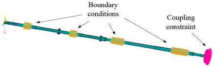
The boundary conditions include displacement and rotation constraints on the bearings. The displacement constraints are set in the longitudinal direction, namely along with the direction of the shaft. The rotation constraints are set in the radial direction, namely along with the rotational direction of the shaft. All the boundary conditions are defined at the outer edge of the bearings to simulate the supporting effects on the shaft system. In particular, coupling degrees of freedom into a set may cause the members of the set to have the same calculated results. For structural analysis, a set of coupled nodes are defined along with the nodal directions. Due to their coupling relationship, these nodes are forced to take the same displacement in the specified nodal coordinate direction [22]. In our simulation, the coupling constraint is applied on the propeller, namely coupling the mass unit with solid elements of the same section. Thus, the two kinds of elements have the same displacement and rotation. The meshed finite element model of marine propulsion shafting with boundary conditions and coupling constraint is shown in Fig. 3.
Fig. 3The meshed finite element model with boundary condition
The rotational speed of idling vibration in numerical simulation is set as the same as that under experimental conditions. The marine propulsion shafting is not affected by any external force under different rotational speeds. In the simulation with force vibration, the transverse force is applied to the above coupled finite element model, and the value and position of transverse loading in the coupled FEA method are consistent with those in experimental tests. In dynamic analysis of marine propulsion shafting, the natural frequency and ultimate displacement can be obtained through harmonic analysis and transient analysis respectively. Thus, the dynamic simulation results can be acquired by the coupled FEA method.
Through numerical simulation, the natural frequency and ultimate deformation of all nodes in the coupled FEA model can be obtained. Among all nodes, the one at the same position of experimental test is selected to make a comparison. The simulation results at different rotational speeds and loading states are compared by the following experimental tests to verify the accuracy of the coupled FEA method.
4. Experimental tests
The propulsion shafting experimental platform is mainly composed of the frequency conversion motor, the decelerator, the thrust bearing, the propulsion shafting, the foundation and the base. Besides, it is equipped with water lubrication system, oil lubrication system, hydraulic loading system and state monitoring system. The base is mounted on the foundation, and the shafts and bearings are mounted on it. The propulsion shafting comprises two intermediate shafts and a tail shaft, and all shafts are connected to the hydraulic couplings. The intermediate shafts are supported by intermediate bearings, and the tail shaft is supported by a water lubricated stern bearing and an oil lubricated front tail bearing.
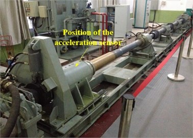
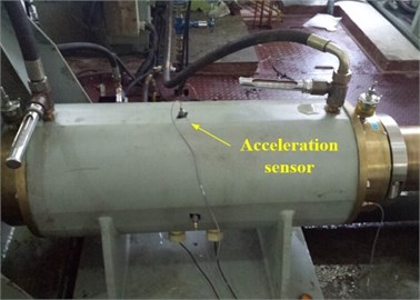
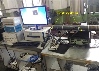
The experimental platform is the major installation to carry out vibration experiments of the marine propulsion shafting. By virtue of various detecting instruments, the platform can monitor different running states of the propulsion shafting, such as orbit of shaft center, reaction force of bearings, shafting vibration of multi direction. In vibration test, the acquisition and analysis of vibration signals are mainly completed by acceleration sensor and relevant vibration analyzer. Fig. 4 presents the experimental platform of marine propulsion shafting, as well as the position of acceleration sensor.
Fig. 4The shaft experimental platform and the acceleration sensor
In the process of experimental data acquisition, the vibration signals from different directions are collected and analyzed synchronously by some relevant vibration analyzers. These analyzer instruments can accurately display the vibration information of the shaft in time domain. The response in frequency domain can be obtained by the written software program with FFT transformation. In this study, the main task of vibration test is to measure the coupled dynamical response of marine propulsion system under idling and loading conditions. The dynamical response includes harmonic analysis and transient analysis of the accelerated velocity under various rotational speeds.
Fig. 5The water lubrication system and the test process
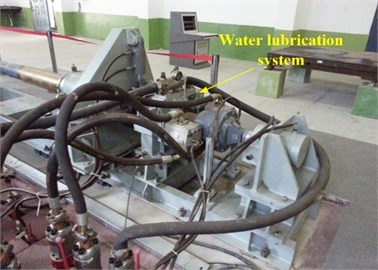
In vibration test without external force, a multichannel signal analyzer is used to collect and analyze the data of sensors synchronously. The vibration signal of propulsion shafting can be acquired by the test system and displayed on the personal computer accurately, as the Fig. 5 shows.
In vibration test with transverse force, the external loading is applied by the water hydraulic system installed between the tail bearing and the propeller, as Fig. 5 shows. The water hydraulic system consists of two exciters, respectively in horizontal direction and vertical direction. The exciter in horizontal direction is used for simulating the excitation of hull deformation and that in vertical direction is for simulating the excitation of ship rolling. Some mechanical sensors are installed on the exciters to monitor and control the value of the force through connecting with the main test system. In order to avoid shaft damage by excessive stress, the value of transverse force is set as 3 MPa in the permit of laboratory conditions, and the applied position at the tail of the shaft is showed in Fig. 5.
The power of motor is about 55 kW and the limit rotational speed of the test instrument is about 550 revolutions per minute. In order to ensure the accuracy, the maximum rotational speed of the experimental test is set as 360 revolutions per minute. Meanwhile, to ensure the completeness of experimental data, the dynamic response of marine shafting system is measured under five different rotational speeds, i.e., 60 r/min, 100 r/min, 160 r/min, 260 r/min and 360 r/min. Under idling and loading conditions, the natural frequency and ultimate deformation of marine propulsion shafting are tested, and the experimental data for each scheme are extracted and recorded from the acceleration sensor on the tail bearing.
5. Solution analysis
The dynamic analysis of coupled transverse and longitudinal vibration for propulsion shafting includes harmonic analysis and transient analysis. Harmonic response analysis is used to determine the steady-state response of structure under changing loads, while transient analysis is to determine the displacement or stress response of each point on structure under changing loads.
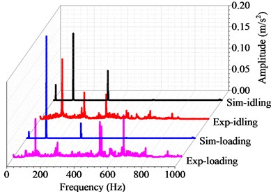
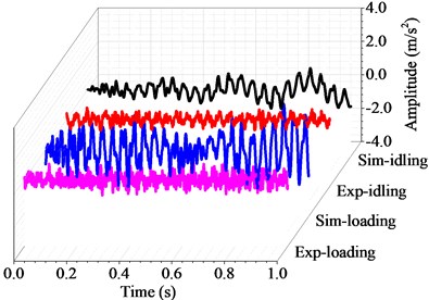
Figs. 6 to 10 show the harmonic analysis and transient analysis of the propulsion shafting under different rotating speeds. As can be seen, the natural frequency does not change with the rotational speed or under the transverse force, whereas the ultimate deformation of transient analysis becomes larger and larger with increasing rotational speed or under the effect of transverse force. These experimental results agree well with the simulation results from above curve diagrams, that is to say, the accuracy and applicability of the coupled finite element method are desirable for the vibration research of marine propulsion shafting.
Dim that:
Case 1: simulation results of vibration without load (abbreviated as Sim-idling);
Case 2: experimental results of vibration without load (abbreviated as Exp-idling);
Case 3: simulation results of vibration with load (abbreviated as Sim-loading);
Case 4: experimental results of vibration with load (abbreviated as Exp-loading).
Fig. 6Harmonic and transient response with the rotating speed of 60 r/min
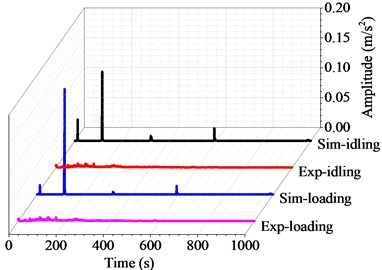
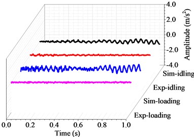
Fig. 7Harmonic and transient response with the rotating speed of 100 r/min
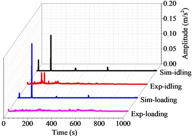
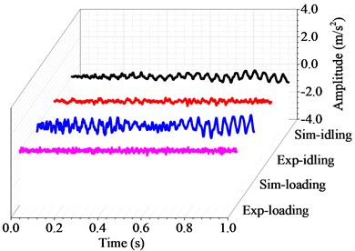
Fig. 8Harmonic and transient response with the rotating speed of 160 r/min
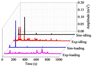
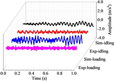
Fig. 9Harmonic and transient response with the rotating speed of 260 r/min
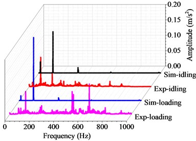
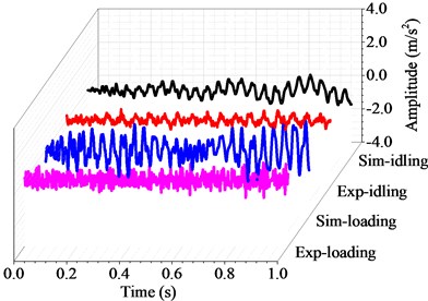
Fig. 10Harmonic and transient response with the rotating speed of 360 r/min
During actual measurement process, the marine shafting may suffer from the friction force such as oil film resistance and damping effect, the deviation appear in the process of experimental measurement, and the precision of the applied experimental instrument. As a result, there may be some deviation for the natural frequency nder different rotational speeds in experimental tests. However, this deviation is acceptable within the range of experimental error.
Table 1 shows the harmonic responses results of the coupled vibration by the finite element method and the experimental tests. For the numerical results, the natural frequency keeps at 116.3 Hz under both idling and loading conditons. In contrast, the natural frequency of the experimental results ranges from 92.5 Hz to 130.6 Hz under idling conditon, and from 100.6 Hz to 131.9 Hz under loading conditon (3 MPa) at different rotational speeds. Both the experimental and simulation results show that the natural frequency of the shafting system is an intrinsic property of the shafting structure, which does not change with the rotational speed or external force. This means that the hull deformation can not change the natural frequency of the propulsion shafting.
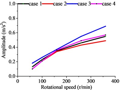
Table 2 shows the transient responses results of the coupled vibration by the finite element method and the experimental tests. Since transient response is a periodic function in time domain, its average values in the whole time domain can be obtained through averaging the peak values of all motion cycles. In the case without external force, the average deformation of the simulation results ranges from 0.13 m/s2 to 0.55 m/s2, and that of the experimental results ranges from 0.10 m/s2 to 0.49 m/s2 at different rotational speeds. In the case with external force, the average deformation of the simulation results ranges from 0.18 m/s2 to 0.69 m/s2, and that of the experimental results ranges from 0.10 m/s2 to 0.57 m/s2 at different rotational speed. As the rotational speed increases, the dynamic responses of marine propulsion shafting becomes more intense. Meanwhile, the external force also affects the coupled response, and the ultimate displacement of marine propulsion shafting becomes larger under the effect of transverse force.
Table 1Harmonic response results
Scheme | 1. Simulation (idling) | 2. Experiment (idling) | 3. Simulation (loading) | 4. Experiment (loading) |
60 r/min | 116.3 Hz | 92.5 Hz | 116.3 Hz | 135.0 Hz |
100 r/min | 116.3 Hz | 118.1 Hz | 116.3 Hz | 118.8 Hz |
160 r/min | 116.3 Hz | 95.0 Hz | 116.3 Hz | 100.6 Hz |
260 r/min | 116.3 Hz | 95.0 Hz | 116.3 Hz | 131.3 Hz |
360 r/min | 116.3 Hz | 130.6 Hz | 116.3 Hz | 131.9 Hz |
Table 2Transient response results
Scheme | 1. Simulation (idling) | 2. Experiment (idling) | 3. Simulation (loading) | 4. Experiment (loading) |
60 r/min | 0.13 m/s2 | 0.10 m/s2 | 0.18 m/s2 | 0.10 m/s2 |
100 r/min | 0.23 m/s2 | 0.21 m/s2 | 0.26 m/s2 | 0.21 m/s2 |
160 r/min | 0.35 m/s2 | 0.34 m/s2 | 0.37 m/s2 | 0.36 m/s2 |
260 r/min | 0.46 m/s2 | 0.43 m/s2 | 0.55 m/s2 | 0.49 m/s2 |
360 r/min | 0.55 m/s2 | 0.49 m/s2 | 0.69 m/s2 | 0.57 m/s2 |
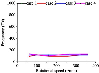
The results from the finite element method and the experimental tests show that there is a fiducial interval for the dynamic results of the marine propulsion system, as shown in Fig. 11. This region should be incorporated in the vibration control of the propulsion shafting so as to ensure the effectiveness of the propulsion system. The acceleration curves of the vibration results point out the motion trend of marine propulsion shafting.
It can be seen that the dynamic performance of propulsion shafting at any rotational speed can be predicted through the coupled FEA method. The critical frequency and ultimate acceleration can be acquired through harmonic response analysis and transient analysis. These basic properties of marine propulsion shafting play an important role in the operation of sailing ships. Therefore, the coupled FEA method provides effective technical support for vibration prediction of the marine propulsion system.
Fig. 11Dynamic response results with various rotating speed
6. Conclusions
In summary, a coupled FEA method is proposed in this paper to study the vibration performance of marine propulsion shafting under idling and loading conditions. The dynamic behaviors of coupled torsional and transverse vibration at different rotational speeds are studied through numerical simulation and experimental tests, and the natural frequency and ultimate deformation of the marine propulsion shafting are discussed in details. Some conclusions can be drawn as follows:
1) The numerical simulation results agree well with experimental test results at different rotational speeds. It proves the accuracy of the coupled finite element method applied in this paper. Within the test error range, the ultimate deformation and natural frequency of the coupled vibration remain the same at different rotational speeds. The coupled FEA method can predict the dynamic response accurately for marine propulsion shafting with torsional-transverse coupling, which provides powerful technical support for the design and manufacturing of marine propulsion shafting.
2) According to numerical simulation and experimental tests, hull deformation has an obvious effect on shafting vibration. The transverse force can enlarge the ultimate displacement in certain way. This results is meaningful for the research on the coupled vibration of marine propulsion system, which is litter noticed by active and traditional passive methods. To address this issue, future work will further study the effect of hull deformation on marine propulsion shafting.
References
-
Zhang G. B., Zhao Y. Reduced-order modeling method for longitudinal vibration control of propulsion shafting. IERI Procedia, Vol. 1, 2012, p. 73-80.
-
Murawski L.,Charchalis A. Simplified method of torsional vibration calculation of marine power transmission system. Marine Structures, Vol. 39, 2014, p. 335-349.
-
Dai L. Y., Zhang Z. H., Sun D. Q. A study on axial, lateral and torsional coupled vibration analysis of marine propulsion system with transfer matrices method. Shipbuilding of China, Vol. 4, 1989, p. 98-106.
-
Zhang H. T., Zhang Z. H., Liu Z. G., et al. A study on coupled axial and torsional vibration of marine propulsion shafting. Shipbuilding of China, Vol. 5, 1995, p. 68-76.
-
Warikoo R.,Haddara M. R. Analysis of propeller shaft transverse vibrations. Marine Structures, Vol. 5, 1992, p. 255-279.
-
Zhang G. B.,Zhao Y., Li T. Y.,Zhu X. Propeller excitation of longitudinal vibration characteristics of marine propulsion shafting system. Shock and Vibration, 2014, p. 413592.
-
Yang Y., Tan W. Y., Huang X. C., Ma J. Optimal design for a VLCC propulsion system based on torsional vibration analysis. Procedia Engineering, Vol. 15, 2011, p. 5378-5383.
-
Yan X. P.,Li Z. X.,Liu Z. L.,Yang P.,Zhu H. H.,Yang Z. M. Study on coupling dynamical theory for interaction of propulsion system and hull of large ships: a review. Journal of Ship Mechanics, Vol. 17, Issue 4, 2013, p. 439-449.
-
Parsons M. G., Srinivas J., Raju V. Mode coupling in torsional and longitudinal shafting vibration. Marine Technology, Vol. 20, 1983, p. 257-271.
-
Wu J. S., Yang I. H., O’Shea P. J., Mechefske C. K. Computer method for torsion-and-flexure-coupled forced vibration of shafting system with damping. Journal of Sound and Vibration, Vol. 180, Issue 3, 1995, p. 417-435.
-
Jang M. O., Kim U. K., Park Y. N., Lee Y. J. A Study on the coupled torsional-axial vibration of marine propulsion shafting system using the energy method. Journal of the Korean Society of Marine Engineers, Vol. 3, 2004, p. 482-492.
-
Murawski L. Axial vibrations of a propulsion system taking into account the couplings and the boundary conditions. Journal of Marine Science and Technology, Vol. 9, 2004, p. 171-181.
-
Zou D. L., Rao Z. S., Ta N. Coupled longitudinal-transverse dynamics of a marine propulsion shafting under superharmonic resonances. Journal of Sound and Vibration, Vol. 346, 2015, p. 248-264.
-
Shi L., Xue D. X., Song X. G. Research on shafting alignment considering ship hull deformations. Marine Structures, Vol. 23, 2010, p. 103-114.
-
Andersen I.,Jensen J. J. Measurements in a container ship of wave induced hull girder stresses in excess of design values. Marine Structures, Vol. 37, 2014, p. 54-85.
-
Chris L. Shaft Alignment and Powertrain Vibration. ABS, 2011.
-
Šverko D. Hull deflections shaft alignment interaction, a case study. Proceedings of the 7th International Symposium on Marine Engineering, Tokyo, 2005.
-
Huang Q. W., Liu J., Zhang C., Yan X. P. Analysis on propulsion shafting coupled torsional-longitudinal vibration under different applied loads. Proceedings of 43rd International Congress on Noise Control Engineering, Melbourne, 2014.
-
Hassan S., Mehrdaad G. Free vibration of Timoshenko beam with finite mass rigid tip load and flexural-torsional coupling. International Journal of Mechanic Science, Vol. 48, 2006, p. 763-779.
-
Xu X. Research on the Theory and Experiment of Coupled Vibration for Marine Complex Propulsion Shafting. Ph.D. Dissertation, Wuhan University of Technology, 2012.
-
Lin T. R., Pan J., O’Shea P. J., Mechefske C. K. A study of vibration and vibration control of ship structures. Marine Structures, Vol. 22, 2009, p. 730-743.
-
Mechanical APDL (ANSYS) Help 15.0, CP: Defines (or modifies) a set of coupled degrees of freedom.
About this article

The authors give sincere thanks to the editors and the reviewers for their patient work and constructive suggestions. This work is supported by the State Key Program Grant of National Natural Science Foundation of China (No. 51139005).
