Abstract
A circuit breaker often has a fault phenomenon in an electrical circuit, for example, its two contacts are kept away under a vibration environment. This will cause its electrical system not work normally. In the paper, a dynamical model is proposed for the circuit breaker applied with a low voltage under a vibration disturbance when the circuit breaker system is simplified as a cart-inverted pendulum system. Through some mechanical analyses, the nonlinear property of the circuit breaker is studied, and the fault phenomenon of the breaker in the vibration environment is described. With some simulations and experiments, the theoretical model is verified effectively when the circuit break is viewed as a switch in the electric system. Furthermore, the minimum amplitudes of a sinusoidal acceleration applied on the system to make the breaker have a fault phenomenon in the simulations are in good agreement with that in the experiments. Therefore, the dynamical model for representing the fault property of the circuit breaker is demonstrated feasibly with simulations and experiments.
1. Introduction
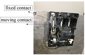
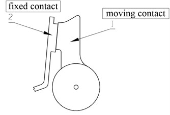
A circuit breaker not only is a basic low voltage device but also is an important kind of switch used in power system. Shown in Fig. 1(a), a circuit breaker is installed on the wall of an electrical box. From Fig. 1(b), the breaker is consisted of two contacts. One is the moving contact; the other is the fixed contact. If the two contacts are closed, then the electricity is turn on. When the two contacts are kept away, the electricity is turn off. Because of that, the breaker can turn on, bear and break the normal or overloaded current in a circuit within limited time. Therefore, it is widely used in the industrial installations, for example, rail systems, electric vehicles and ship fields. However, once there is a fault phenomenon for the circuit breaker system, the system doesn’t work properly. To improve instantaneous protection reliability, an instantaneous failure mechanism of low voltage circuit breakers was analyzed [1]. Especially in a complex environment (a vibration caused by the external disturbance), the breaker has a higher chance of being in a failure state. A vibrational analysis was carried out by analyzing the signal in the time-frequency domain under no-load switching operations with a commercially available high-voltage puffer-type circuit breaker without opening its major parts [2]. So, describing the fault phenomenon of a circuit breaker in the vibration environment is very necessary for improving security in industrial electrical equipment.
For the failure property of the circuit breaker, there were several methods proposed by many researchers. The most common method was empirical mode decomposition (EMD). For example, based on EMD method and support vector machine (SVM), a new method for the fault diagnosis of high voltage circuit breaker (CB) was proposed [3], an extraction method based on ensemble empirical mode decomposition (EEMD) was presented and was verified effectively by the practical examples for identifying the fault patterns of HV circuit breaker [4] and a new method based on improved empirical mode decomposition (EMD) energy entropy and multi-class support vector machine (MSVM) was proposed to diagnose fault for high voltage CB [5]. But this identification method couldn’t represent the mechanism of the fault phenomenon for the circuit breaker, because this fault property is often a kind of nonlinearity characteristic. Therefore, some innovative ways were presented in present years, an Expert System (ES) with the addition of a signal processor module and factual database module to the conventional ES has been proposed for the diagnosis of CBs and OLTCs [6]. A Least Squares Support Vector Machines (LS-SVM) based CB maintenance scheduling optimization approach that considers constraint of cost effect was proposed [7]. Furthermore, the application of vibration analysis was dealt successfully with for circuit-breaker (CB) diagnostic testing with the aim of detecting mechanical anomalies in CB drive mechanisms and other moving parts in the interrupting chamber [8]. However, regardless of which method was taken, a detailed force analysis must be implemented before studying the fault phenomenon for a circuit breaker.
In the paper, a circuit breaker in a vibration environment is simplified as a cart-inverted pendulum system, a dynamical model is proposed by the Newton’s Second Law. And some simulations and experiments are carried out to verify the nonlinear model. Obviously, the model is demonstrated to be feasible. The rest of this paper is organized as follows: a dynamical model for a circuit breaker with an external vibration disturbance is obtained by describing its failure phenomenon in Section 2. Some simulation and experiment results are shown and some discussions are presented in Section 3. Finally, some conclusions are given in Section 4.
Fig. 1A circuit breaker
a)
b)
2. Description for the fault phenomenon of the breaker system
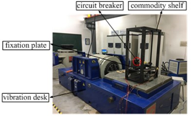
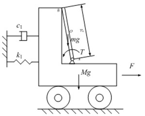
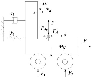
In the paper, by simplifying the circuit breaker system, a dynamic model with mechanical analysis is presented for describing the nonlinearity of a low voltage circuit breaker under a vibration environment. Fig. 2(a) shows the circuit breaker system on a vibration desk. The vibration desk provides a vibration environment, such as a sinusoidal signal or a random signal. The beaker is fixed on the steel plate, and the fixation plate and the commodity shelf are installed on the vibration desk. Fig. 1(b) gives a detailed drawing of the breaker, and the label 1 and the label 2 represent the static contact and the moving contact of the breaker respectively. The static contact is fixed on the steel plate, but the moving contact can rotate around a fixed axle. Therefore, shown in Fig. 2(b), the vibration desk with fixation plate and the fixed contact is simplified as a cart applied with an external vibration disturbance on a smooth horizontal plane, while the moving contact is simplified as a rod leaning against the cart with a preloaded moment . At a word, the circuit breaker in a vibration environment is simplified as a cart-inverted pendulum system.
The cart-inverted pendulum system is decomposed into a cart and an inverted pendulum, and their forces analysis is shown in the Fig. 3. For the cart in Fig. 3(a), according to Newton’s Second Law, the mechanical formulas along the and directions of the cart are expressed as:
where is the displacement of the cart along the horizontal direction, is the mass, and are the forces applied by the inverted pendulum’s A end and B end respectively, and and are the support forces by the ground. and are the damping coefficient and spring constant respectively. And is the friction.
Fig. 2Experimental setup and diagram of the breaker system
a)
b)
Fig. 3Forces analysis of the system
a)
b)
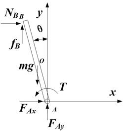
Fig. 3(b) shows the forces analysis of the inverted pendulum, and the mechanical formulas are given as:
where:
is the mass of the inverted pendulum, is moment of inertia, and is half of the length of the pendulum. And . Moreover, is an average torque of the spring in the breaker and represents preload for the moving touch of the breaker, and maintains the stability of the vertical inverted pendulum by making the pendulum to lean against the car. Therefore, the acceleration at the O point of the pendulum is expressed as:
Combining Eq. (1), Eq. (2) and Eq. (3), then the dynamical equation is given as:
where represents that the B end of the inverted pendulum does or doesn’t get off the cart. If 0, the moving contact has been kept away from the fixed contact for the circuit breaker. When 1, the two contacts are closed, the breaker can work normally in the circuit system. The is expressed as:
For above description, a dynamical model is constructed for representing the fault property of a circuit breaker in power system under a vibration environment with forces analysis. In next Section, some simulations and experiments are performed to verify effectively the theoretical model, and some results will be discussed.
3. Simulation and experiment results
When a theoretical model (Eq. (4)) is established by some mechanics principles, some simulation and experiment results are gained to verify effectively the model. Therefore, by MATLAB/Simulink, the Eq. (4) is solved by ODE45 with the corresponding parameters of the model in Table 1, and some simulation verifications are gained. A sinusoidal acceleration (namely /() in Eq. (1) and Eq. (2)) applied on the cart. The sinusoidal signal is set at amplitude 0.5 m/s2 and frequency 30 Hz. Then, the cart has a reciprocating motion, and the displacement of the cart is shown in Fig. 4. Under the sinusoidal force in Eq. (4), the displacement of the cart has a reciprocating value. And isn’t all equal to zero. Therefore, it is obvious that a nonlinear relationship between the sinusoidal acceleration and the displacement of the cart is found. Moreover, for the displacement along the direction of the cart, the maximum amplitude is about 2.7 mm and the frequency is about 30 Hz.
Table 1Corresponding parameters of the model in simulations
280 kg | 0.04 m | 6×10⁶N/m |
0.5 kg | 4 | 9.8 m/s2 |
ml2/12 | 0.9 | 0.001 Nm |
Furthermore, the inverted pendulum has not only a reciprocating motion with the cart but also a rotational motion around point A on the cart in Fig. 3. Therefore, the point B of the inverted pendulum is viewed as that of the moving contact of the circuit breaker. And the initial angle is –5° (–0.0873 rad) when the inverted pendulum leans against the cart. Then when the cart suffers from an acceleration excitation, the whole inverted pendulum system has a motion. At the same time, the point B is separated from the cart and the inverted pendulum is rotating clockwise. However, the inverted pendulum is pulled back by the initial moment . That causes the intermittent contact between the point of the inverted pendulum and the cart. The intermittent contact will affect the work efficiency and life of the break in the mechanical equipment. Therefore, the displacement of the point B is shown is shown in Fig. 5 by a formula . The rotational angle is displayed in Fig. 6 when the point B of the inverted pendulum is far from the cart. Apparently, the rotational angle keeps a constant value –0.0873 rad in a half period when the two contacts are closed. Moreover, the two contacts are opening, and the angle is more than the initial angle –5° (–0.0873 rad) when the moving contact is far from the cart in the vibration environment.
Fig. 4Displacement x of the cart
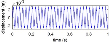
Fig. 5Displacement xB of the point B in the inverted pendulum
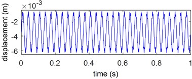
Fig. 6Rotational angle θ of the inverted pendulum
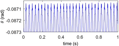
Fig. 7Circuit diagram of the breaker
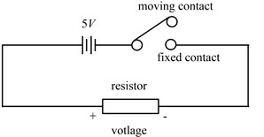
Then the circuit breaker is put in the vibration environment and its contacts are open, shown in Fig. 7. The circuit is viewed as a switch with a moving contact and a fixed contact. When the contacts are closed, the voltage is about 5V. Moreover, when the contacts are far away, the voltage of the resistor is about 0V. If the angle > –5°, the breaker is open and is equal to 0; if the angle ≤ –5°, the breaker is closed and is equal to 1. Furthermore, the voltage of resistor is measured by NI collector. The simulation and experiment results are revealed in Fig. 8. It shows the voltage of the resistor in Fig. 7. When the sinusoidal vibration acceleration is applied on the vibration platform (simplified as a cart in Section 2), the blue line is gained from the model by MATLAB/Simulink and the red dotted data is collected from the experiment. From fitting ration of the blue and red data, the theoretical model can describe effectively the experiment phenomenon.
Fig. 8Voltage of the resistor
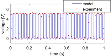
Fig. 9Minimum acceleration amplitude in different frequency
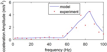
When an acceleration signal is set at a constant frequency and is applied on the cart, the limit amplitude of the acceleration is obtained to keep the moving contact away from the fixed contact of the circuit breaker by some simulations and experiments. The limit acceleration amplitudes in different frequency are given in Fig. 9. The minimum amplitude value of the acceleration to open the breaker under a vibration environment was attained with a different frequency and the minimum amplitude has a peak value at about 85 Hz. The limit value is helpful to set a standard for the reliability of the low voltage breaker under a vibration environment. It is evident that the experimental results are in good agreement with that model results.
4. Conclusions
In the paper, a fault phenomenon of the circuit breaker is described in vibration environment. By the mechanics analyses, the circuit breaker in the vibration environment is simplified as a cart-inverted pendulum system which is applied a vibrational force. Through the Newton’s Second Law, a theoretical model is proposed for the inverted pendulum system. By the simulation in MATLAB, the displacements of the cart and the inverted pendulum are nonlinear. And when the rotational angle of the inverted pendulum is various, the moving contact is kept away from the fixed contact of the circuit breaker. The fault property of the breaker is demonstrated by the theoretical model and the experiment. In future work, some methods will be studied and designed to avoid the fault phenomenon for the circuit breaker.
References
-
Lu J., Du T., Luo Y. Study on the instantaneous protection reliability of low voltage circuit breakers. Journal of Zhejiang University: Science A, Vol. 8, Issue 3, 2007, p. 370-377.
-
Charbkaew N., Suwanasri T., et al. Vibration signal analysis for condition monitoring of puffer-type high-voltage circuit breakers using wavelet transform. IEEE Transactions on Electrical and Electronic Engineering, Vol. 7, Issue 1, 2012, p. 13-22.
-
Huang J., Hu X. G., et al. Support vector machine with genetic algorithm for machinery fault diagnosis of high voltage circuit breaker. Measurement, Vol. 44, Issue 6, 2011, p. 1018-1027.
-
Zhang J. F., Liu M. L., et al. Mechanical fault diagnosis for HV circuit breakers based on ensemble empirical mode decomposition energy entropy and support vector machine. Mathematical Problems in Engineering, Vol. 2015, 2015, p. 101757.
-
Huang J. A., Hu X. G., et al. An intelligent fault diagnosis method of high voltage circuit breaker based on improved EMD energy entropy and multi-class support vector machine. Electric Power Systems Research, Vol. 81, Issue 2, 2011, p. 400-407.
-
Hussain A., Lee S. J., et al. An expert system for acoustic diagnosis of power circuit breakers and on-load tap changers. Expert Systems with Applications, Vol. 42, Issue 24, 2015, p. 9426-9433.
-
Jian L., Tianyuan T. LS-SVM based substation circuit breakers maintenance scheduling optimization. International Journal of Electrical Power and Energy Systems, Vol. 64, 2015, p. 1251-1258.
-
Landry M., Leonard F., et al. An improved vibration analysis algorithm as a diagnostic tool for detecting mechanical anomalies on power circuit breakers. IEEE Transactions on Power Delivery, Vol. 23, Issue 4, 2008, p. 1986-1994.
About this article

This work was supported by the National Natural Science Foundation of China (NSFC) under No. 11702168 and the Shanghai Science and Technology commission local colleges’ capacity building project: 14110501200.
