Abstract
An atomistic Green’s function method hybrid with the finite element method is developed to analyze the mode-dependent elastic wave transmittance in a structure with arbitrary geometries. The validity of the proposed method is demonstrated by the phononic crystal waveguide case and a comparison with the transfer matrix method. This method also can be used to investigate the phonon ballistic transport in a quantum system at low temperatures.
Highlights
- An atomistic Green's function method hybrid with the finite element method is developed.
- The mode-dependent elastic wave transmittance in a structure with arbitrary geometries can be calculated.
- This method can be used to investigate the elastic wave transmission in phononic crystal waveguides, and the phonon ballistic transport in a quantum system at low temperatures.
1. Introduction
Phononic crystals and acoustic metamaterials are artificially designed composite materials capable of manipulating wave propagation, and have unusual physical properties [1, 2]. If the size of the devices reduces to the nanoscale, the heat transfer by phonons in the mesoscopic system can show the wave characteristics [3]. One of the classical topics in all these fields is to calculate the wave transmission coefficient (or transmittance) [4].
This paper presents a method to explore the elastic wave transmission based on the Green’s function method. The nonequilibrium Green’s function method is a powerful tool to study electron transport in the mesoscopic system [5], and was improved to the atomistic Green’s function (AGF) method which can explore the phonon transport mechanism in the semiconductor and dielectric nanostructures [6]. We further extended the AGF method to study the elastic wave transmission between the terminals of device with arbitrary geometries [7]. However, in the traditional AGF method, the calculated transmittance is a summation of the contributions from all modes at a given frequency. Up to now, a lot of work has been made to obtain the mode-dependent transmittances by improving the AGF method [8, 9]. In this paper, the mode-dependent transmittance in a phononic crystal waveguide is calculated by an improved AGF method. This method also can be used to investigate elastic waves in more complicated structures, and phonon ballistic transport in a quantum system at low temperatures.
2. Model and computational methods
The model configuration discussed in this paper has a structure as shown in Fig. 1. The central part is a scattering region, which can be an elastic body with a complex structure. In the case shown in Fig. 1, it is a one dimensional phononic crystal with 3 periods connected with two terminals. This paper is to explore the elastic wave transport across the scattering region between terminals.
The method used in the simulation is an atomistic Green's function method hybrid with the finite element technique [7]. It is difficult to get the analytical Green’s function for the continuous system, e.g. the structure shown in Fig. 1. Therefore, we turn the continuous system into a discrete one by using the finite element method (FEM). The discrete structure is similar to a lattice, which can be studied by the AGF method. The discrete dynamical equation in FEM can be expressed as [10]:
where is the identity matrix, and is the dynamical matrix. Herein we assume . and are mass and stiffness matrix, respectively. is the node amplitude, and is the angular frequency, where is the vibration frequency. The lump mass matrix is a diagonal matrix, widely used in the wave propagation problems [10]. The dynamical matrix in Eq. (1) for the system shown in Fig. 1 has the form of:
where () and stand for the dynamical matrices of the terminals and the scattering region, respectively. The coupling between the terminals and the scattering region is indicated by , where the superscript “” represents the matrix transpose.
Fig. 1A schematic diagram of a one dimensional phononic crystal with 3 periods connected with two terminals. The structure is discretized according to FEM. The numbers in the terminals denote the respective layer indices
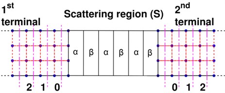
It should be note that the semi-infinite terminals must be discretized into periodic layer structures, and each layer has the same element division as shown in Fig. 1 [7]. The terminals, therefore, have a periodic layer structure, and the unit layers are numbered in sequence according to the distance from the scattering region. Then the dynamical matrix of the -th terminal can be written as:
The terminal is characterized by and , which can be used to calculate the phonon dispersion based on the equation expressed as [4, 9]:
where represents the phonon eigenvector corresponding to the -th unit layer in the -th terminal. is the Bloch phase factor, where and denote the wave number and the period of the unit layer along the terminal direction, respectively. In Eq. (4), , where is a small positive perturbation and is the unit of imaginary number. If the eigenvalue , Eq. (4) gives an outgoing wave propagating away from the scattering region along the terminal. All the normalized vectors of the outgoing waves are combined together to form a matrix and the corresponding eigenvalue matrix is a diagonal matrix. At frequency , there are wave modes including the propagating modes and evanescent modes. The propagating modes always have real wave number and propagate stably in the terminal, while the evanescent modes will exponentially decay because of the complex wave number.
The system in Fig. 1 is infinite. However, we can project the dynamics of the infinite system to the finite scattering region via self-energies [11], where the surface Green’s function of -th terminal corresponding to nodes in the 0th layer is given by:
In the above equation, is the propagator [12] used to describe the propagation of the waves along the unit layers in the terminal. Then the Green’s function for the scattering region is defined as [7]:
The mode-resolved wave transmittance is based on the matrix written as [8]:
where , and the group velocity matrix of -th terminal is defined as:
where . The superscript “*” represents the complex conjugate transpose operation. Then the transmittance between the -th mode in the -th terminal and the -th mode in the -th terminal is defined as the square modulus:
3. Results and discussion
The wave transmission is a classical topic in the field of acoustic metamaterials and phononic crystals [1] and heat transfer research [7]. Fig. 1 illustrates an example in which the scattering region is a superlattice structure. The superlattice is comprised of two layers of different materials denoted by (Aluminum) and (Epoxy resin), respectively. There are three periods. The terminals are aluminum. The density, Young’s modulus and shear modulus of aluminum are 2730 kg/m3, 7.76×10¹⁰ Pa and 2.87×10¹⁰ Pa, and these of epoxy resin are 1180 kg/m3, 4.35×10⁹ Pa and 1.59×10⁹ Pa. All the layers in the scattering region have the exact same thickness of 0.075 m. The width of the structure is 0.015 m. The in-plane vibration in the quasi-one-dimensional thin plate in Fig. 1 is described as a plane stress problem. The bilinear quadrilateral element [10] having four nodes is used. Each square element has a width of 0.0025 m.
Fig. 2 illustrates the phonon dispersion of the terminals, which is calculated by using Eq. (4). The terminals are discretized into periodic layer structures as shown in Fig. 1, and the layer width is 0.0025 m. In the frequency range from 0 to 30 kHz, there are two in-plane acoustic branches: the longitudinal (LA) branch and the transverse (TA) branch. These two branches are propagating modes having the real wave number.
Fig. 3(a) presents the frequency dependence of the calculated total transmittance , which is obtained by summation of mode contribution by using Eq. (9). The total transmittance is the key quantity in solving the thermal conductance in the field of nanoscale heat transfer [4]. If the structure is homogeneous, we can obtain the upper limit of the total transmittance, because all the modes are taken into account without interface scattering. The upper limit value takes on integer values of the number of phonon modes, and the value is 2 due to the two acoustic branches shown in Fig. 2. It appears that is sensitive to the wave frequency with alternating prominent dips and sharp peaks.
Fig. 2Phonon dispersion of the terminal
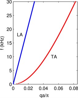
Fig. 3Plot of a) the total transmittance and b) the transmittance of LA and TA waves denoted by the blue and red lines, respectively. The dots stand for the result of transfer matrix method
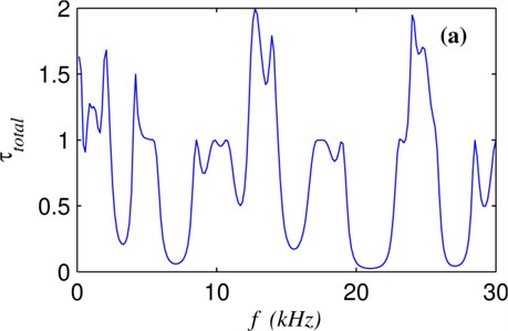
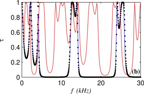
The contributions to the total transmittance come from two branches. The more detailed mode-resolved analysis is helpful to explore the wave transmission mechanism in the system. Although there are only 3 periods in superlattice structure in Fig. 1, the transmittance of individual branch in Fig. 3(b) clearly reveals the position of stop bands of the phononic crystal for LA and TA waves in the range from 0 to 30 kHz. LA and TA waves have different frequency dependence of wave transmittance because the two waves have different velocities [13]. The scattering region herein has a simple layer structure, which can be simulated by the transfer matrix method [13]. The result of transfer matrix method for the LA wave can be taken as the benchmark solution denoted by dots in Fig. 3(b). The well match between the dots and the blue line demonstrates the validity of the proposed method.
4. Conclusions
An AGF method hybridized with FEM method with lump mass matrix is developed for the analysis of the polarized elastic wave transmittance. The proposed method is also suited to study the ballistic phonon heat transport in nanostructures of arbitrary shape at low temperatures. The first step of the method is to discretize the elastic body into nodes and elements by the FEM. Then the nodes act as atoms allocated with mass according to the lump mass method, and the stiffness matrix stands for the interaction between atoms. The equivalent lattice system is studied by the AGF method capable of revealing the polarized phonon transmittance between terminals. The validity of the proposed method is demonstrated by calculating the wave transmittance in a phononic crystal waveguide with a comparison with the transfer matrix method simulation. The proposed method is helpful to better understand the elastic wave transmission in complicated structures to the level of individual branches.
References
-
Deymier P. A. Acoustic Metamaterials and Phononic Crystals. Springer, New York, 2013.
-
Banerjee A., Das R., Calius E. P. Waves in structured mediums or metamaterials: a review. Archives of Computational Methods in Engineering, 2018, https://doi.org/10.1007/s11831-018-9268-1.
-
Maldovan M. Phonon wave interference and thermal bandgap materials. Nature Materials, Vol. 14, Issue 7, 2015, p. 667-674.
-
Wang J. S., Wang J., Lu J. T. Quantum thermal transport in nanostructures. The European Physical Journal B, Vol. 62, Issue 4, 2008, p. 381-404.
-
Datta S. Quantum Transport: Atom to Transistor. Cambridge University Press, New York, 2005.
-
Mingo N., Yang L. Phonon transport in nanowires coated with an amorphous material: An atomistic Green's function approach. Physical Review B, Vol. 68, 2003, p. 245406.
-
Gu Y., Wang J. Green's function method hybrid with the finite element method for ballistic phonon transport at low temperatures in nanostructures of arbitrary shape. Numerical Heat Transfer, Part B: Fundamentals, Vol. 72, Issue 1, 2017, p. 71-81.
-
Ong Z. Y., Zhang G. Efficient approach for modeling phonon transmission probability in nanoscale interfacial thermal transport. Physical Review B, Vol. 91, Issue 17, 2015, p. 174302.
-
Sadasivam S., Waghmare U. V., Fisher T. S. Phonon-eigenspectrum-based formulation of the atomistic Green's function method. Physical Review B, Vol. 96, 2017, p. 174302.
-
Cook R., Malkus D., Plesha M., Witt R. Concepts and Applications of Finite Element Analysis. John Wiley and Sons, New York, 2002.
-
Ong Z. Y. Atomistic S-matrix method for numerical simulation of phonon reflection, transmission, and boundary scattering. Physical Review B, Vol. 98, Issue 19, 2018, p. 195301.
-
Wang J., Wang J. S. Single-mode phonon transmission in symmetry-broken carbon nanotubes: Role of phonon symmetries. Journal of Applied Physics, Vol. 105, 2009, p. 063509.
-
Maldovan, Thomas E. L. Periodic Materials and Interference Lithography for Photonics, Phononics and Mechanics. Wiley-VCH Verlag GmbH & Co., Weinheim, 2009.
About this article

This research was funded by the National Natural Science Foundation of China through Grant No. 51376094, Jiangsu Overseas Visiting Scholar Program for University Prominent Young & Middle-aged Teachers and Presidents, and the Natural Science Foundation of Jiangsu Province (Grant Nos. BK20160935).
