Abstract
With large number of municipal solid waste incineration power generation plants appearing, serious environmental pollution will be caused if temperature cracks appear in waste bunkers. To reveal the interaction between the surrounding soil and bunker walls under the action of temperature, a finite element model is established. Considering the surrounding soil layer, the characteristics and influence laws of the interaction between the municipal solid waste bunker and the soil under different temperature conditions are studied. The simulation results show that the existence of the surrounding soil layer will affect the stress distribution, mainly at the bottom of the bunker and the surface of the bunker wall. Due to the thermal expansion and contraction, the municipal solid waste bunker is pressed during the heating process. In the process of cooling, there will be excessive tensile stress at the bottom of the bunker. To address this problem, expansion belt is arranged at the stress concentration portion to reduce the stress concentration. This measure proves to be effective according to analysis results, which provides a reference for the design of municipal solid waste bunkers.
Highlights
- Consider the impact of soil on waste bunker
- Use the visco-elastic boundary to simulate the infinite soil layer
- Analyze the temperature stress generated in the waste bunker in different seasons
- Consider the expansion belt to strengthen waste bunker
1. Introduction
With the rapid development of social economy and the increasing population, the speed of urbanization is also rapidly progressing. Therefore, waste and industrial waste are also increasing rapidly, and urban waste disposal has become a tough problem.
The current urban waste treatment methods mainly include sanitary landfill, high temperature composting and incineration. Landfill treatment requires a large amount of land, and harmful components in the waste products will pollute the atmosphere, soil, and water sources, seriously damage the ecological environment and adversely affect human health. High temperature composting is another waste treatment method. The organic matter with high organic content is selected to form organic fertilizer through fermentation. However, composting does not reduce land use and still requires a large amount of land. The incineration process method first burns the waste in an incinerator to release heat, and the rest of the heat can be recovered for heating or power generation. The flue gas is discharged after purified. The flue gas is discharged after purified and small amount of residue is landfilled or used for other purposes. The method has the advantages that the high temperature is harmless, the occupied area is not large, the influence on the surrounding environment is small, and the heat generated by the garbage incineration can be used for power generation, realizing waste resource utilization and saving energy. Therefore, incineration of waste is an effective treatment which is harmlessness and recycling [1]. With the development of society, people's environmental awareness has been continuously improved, and comprehensive utilization technologies such as heat recovery have been improved. The proportion of household waste treatment technology using incineration technology is increasing year by year [2-4].
A large number of municipal solid waste (MSW) incineration power generation plants appear, and it will cause serious environmental pollution when cracks appear in waste bunkers. The safety and applicability of the MSW bunkers are of great concern. So severe requirements should be put forward in the design with influence of temperature considered. Preventing cracks in the MSW incinerator under the action of temperature and propose improvement measures to ensure safety is an important research content.
In this paper, an MSW bunker in a waste-to-energy plant is taken as a typical example. By simulating the MSW bunker and the surrounding soil layer, the stress change law of the MSW bunker under temperature increase and decrease conditions are studied. Accordingly, the improvement measures are proposed, and the stress before and after improvement is compared to provide reference for the design of the MSW bunker.
2. Model establishment
As shown in Fig. 1, the size of the MSW bunker model which is cast in the field using C40 reinforced concrete is 36 m ×18 m × 8 m, and the wall thickness is 0.4 m. The bunker model is surrounded by medium hard soil with the size 180 m × 60 m × 24 m. The elastic modulus of soil is 600 MPa, the density is 2000 kg/m3, the Poisson’s ratio is 0.25, and the thermal expansion coefficient is 5×10⁻⁷. The model of soil layer is shown in Fig. 1(b). The bunker is embedded in the soil for 3 meters. A seam element is connected between the incinerator and the soil layer, and there is only pressure between them.
Fig. 1Analysis model
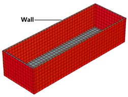
a) MSW bunker
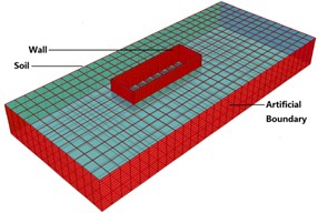
b) Soil layer
3. Viscoelastic artificial boundary
There are two simulation methods to simulate soil boundary around the MSW bunker, i.e., 1) setting the far boundary; and 2) setting the viscoelastic artificial boundary. For the first method, a distance of up to 2000 m will ensure the accuracy of the results, however the computational cost of is excessively high. The artificial boundary method proposed by Liu [5] can be used to analyze the structure-foundation dynamics through structural analysis software, and achieve the effect of simulating semi-infinite foundation in the structure-foundation dynamic interaction problem. Later, Gu and Liu [6] derived the stiffness and damping matrix of the three-dimensional uniform viscoelastic artificial boundary based on the viscoelastic artificial boundary. The accuracy of the artificial boundary is similar to that of the discrete artificial boundary, but its application is broader due to its simplicity. Therefore, in this paper the viscoelastic boundary is used to simulate the infinite soil layer.
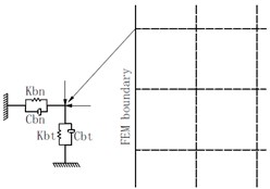
The viscoelastic artificial boundary used here is a continuous artificial boundary condition. According to the work done by Liu [7], it is shown that the viscoelastic artificial boundary is stable and accurate enough. The viscoelastic artificial boundary and the surrounding computational area are discretized by the finite element method, and the concentrated viscoelastic artificial boundary is obtained by the centralized processing method. The viscoelastic artificial boundary can be equivalent to the unit node at the artificial truncation boundary. The normal and tangential parallel spring damper unit set at each node is shown in Fig. 2.
Fig. 2Viscoelastic artificial boundary
The tangential and normal damping coefficients and spring stiffness of the artificial boundary are given by [8].
Tangential boundary:
Normal boundary:
where the values of and are [0.5, 1.0] and [1.0, 2.0]. In this paper, the values of and are set to 0.5 and 1.0 respectively.
In the dynamic analysis of site seismic response, the ground motion input is a key part. The viscoelastic boundary transforms the seismic input problem into a wave source problem, and the ground motion input is transformed into an equivalent load acting on the artificial boundary. For more details about the calculation of equivalent load on the viscoelastic artificial boundary, one can refer to the equivalent load inputting method proposed by Liu [8]. The stress on the artificial boundary node is , and the expression is calculated by the following formula:
where is the known incident wave field, is the stress generated by the displacement in the original continuum, and and correspond to the damping , and stiffness , in Eqs. (1) to (2).
4. Results and discussion
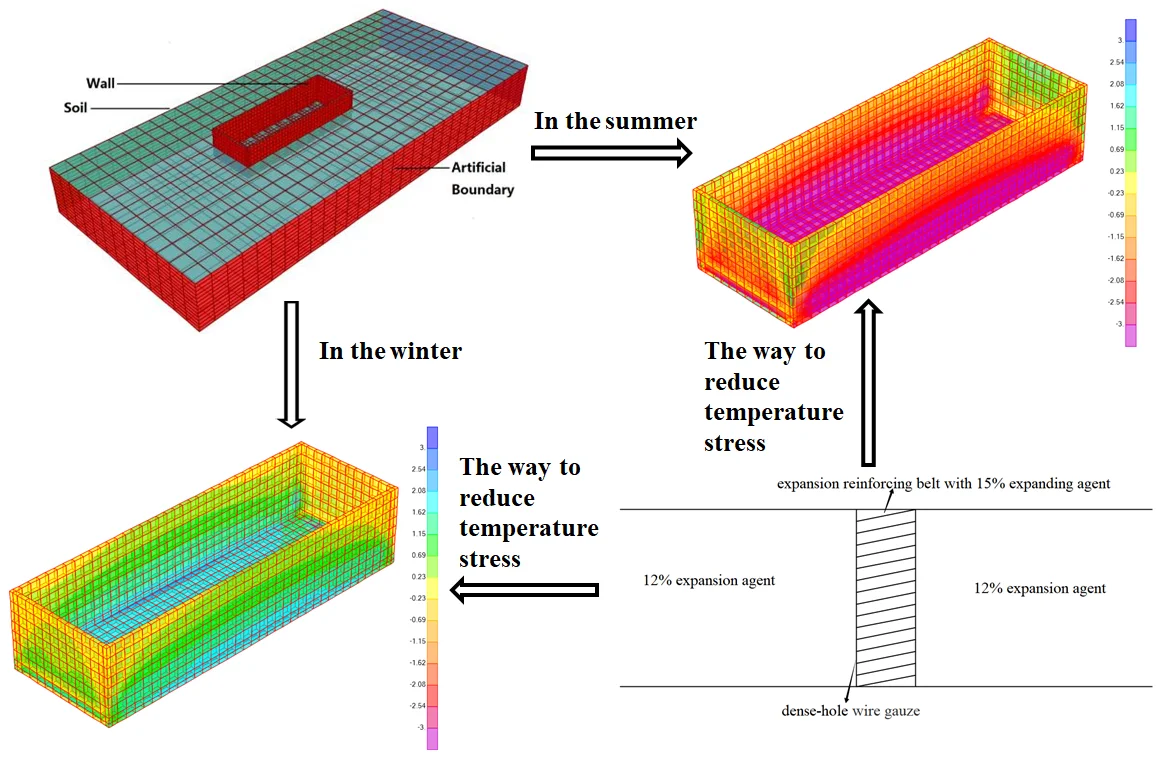
According to the seasonal statistics of the region where the plant is located, the temperature rises about 21 °C in summer and the temperature drops about 19 °C in winter.
4.1. Temperature rising in the summer
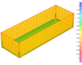
The Fig. 3 shows the stress contour of the waste bunker when the temperature rises by 21 °C. It can be seen that the stress along the wall of the incinerator is the compressive stress in the subterranean part and the maximum value is 3.75 MPa. The stress in the part above ground level is the tensile stress and the maximum is 1.58 MPa, which is mainly because thermal expansion and contraction of the concrete is subjected to the confinement of the surrounding soil. Therefore, the subterranean part of the bunker is under pressure while the part above ground level is under tensile. The maximum normal stress along the bunker wall appears at the four corners of the subterranean part, the maximum value is about 2.44 MPa (compressive stress). The maximum stress along the vertical direction of the bunker wall appears at the surface of soil layer, the maximum value is about 1.70 MPa (tensile stress).
The maximum stress in the longitudinal direction of the bottom of the bunker appears at the bottom of the short side wall, which is about 5.78 MPa (compressive stress), and the rest is about 4.04 MPa (compressive stress). The maximum stress in the transverse direction appears at the edge of the bottom, which is about 2.59 MPa (compressive stress), the rest is about 1.29 MPa (compressive stress). The vertical stress at the bottom of the bunker appears at the edge of the bottom, the maximum is about 0.47 MPa (tensile stress), and the rest of the position is very small.
It can be seen that in the case of temperature rising, the parts with large stress in the MSW bunker are concentrated at ground level and due to the thermal expansion and contraction. The subterranean part MSW bunker in is under pressure, so the risk of crack of the MSW bunker is relatively small when the temperature rises.
Fig. 3Stress of the bunker during the process of temperature rising in the summer.
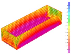
a) Tangential stress
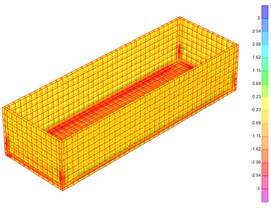
b) Normal stress
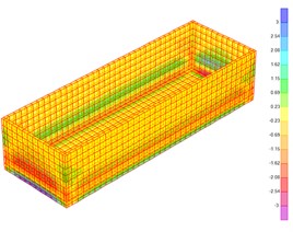
c) Vertical stress
4.2. Temperature dropping in the winter
Fig. 4 shows the stress contour of the MSW bunker when the temperature drops by 19°C. It can be seen that the stress along the bunker wall direction is the tensile stress in the subterranean part, the maximum is 1.74 MPa, the maximum tensile stress at the ground level is 1.01 MPa and the maximum compressive stress is 0.75 MPa. The subterranean part is under tensile while the part at the ground level is under pressure. The maximum normal stress along the wall appears at the four corners of the underground part, and the maximum value is about 1.06 MPa (tensile stress). The maximum stress along the vertical direction of the bunker wall appears at the surface of soil layer, with a maximum of about 0.58 MPa (tensile stress).
Fig. 4Stress of the bunker during the process of temperature rising in the winter
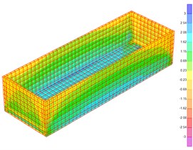
a) Tangential stress
b) Normal stress
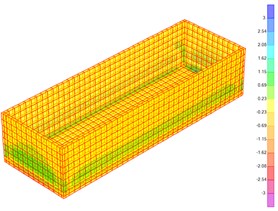
c) Vertical stress
The maximum stress in the longitudinal direction of the bottom of the incinerator appears at the bottom of the transverse side of the bunker wall, which is about 2.56 MPa (tensile stress), and the rest is about 1.88 MPa (tensile stress). The maximum stress in the transverse side direction appears at the edge of the bottom, which is about 1.07 MPa (tensile stress), and the rest is about 0.43 MPa (tensile stress). The vertical stress at the bottom of the bunker appears at the edge of the bottom, the maximum is about 0.60 MPa (tensile stress), and the rest of the stress is small.
Similar to the temperature rise condition, the parts with large stress in the MSW bunker are concentrated at the ground level. On the contrary, the MSW bunker in the subterranean part is under tensile. At the bottom edge of the transverse bunker wall appears large stress in direction along the longitude side which indicates that these regions need to be strengthened.
The maximum value of stress is shown in Table 1 for above two cases. It can be seen that the influence of temperature on the MSW incinerator cannot be ignored.
Table 1The maximum stress in two conditions
Location | Temperature stress (MPa) | ||
Temperature rise | Temperature drop | ||
Wall | Tangential | –3.75 (Underground) 1.58 (Above ground) | 1.74 (Underground) –0.75 (Above ground) |
Normal | –2.44 | 1.06 | |
Vertical | 1.70 | 0.58 | |
Bottom | Long side | –5.78 | 2.56 |
Short side | –2.59 | 1.07 | |
Vertical | 0.47 | 0.60 | |
5. Measures to reduce temperature stress
At present, post-casting belt is often used as an effective measure to solve the problem of cracking for the ultra-long structures. Although the post-casting belt can prevent cracks caused by creeping of concrete, it does not prevent temperature cracks. It will also affect the construction period. Therefore, in the past decade, construction has been more inclined to use expansion concrete to prevent cracks. Expanded concrete is not only inexpensive, but also easy to construct. Because of its good seismic performance, expanded concrete is popular around world [9].
The design idea of the expansive concrete is to use the expansion effect of the compensating shrinkage concrete during the entire hardening process, because the steel bar is restrained by the adjacent position, thereby establishing a small amount of pre-compression stress in the structure. For the sake of structural safety, the expansion should not be too large. According to the research, when the expansion ratio is 2-3×10⁻⁴ and the reinforcement ratio is 0.2-0.8 %, the pre-stress of 0.2-0.7 MPa can be established in the structure.
Fig. 5Layout of the belt and stress at the bottom surface of the bunker
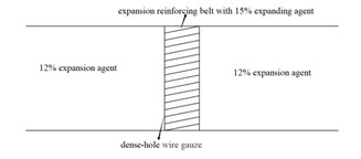
a) Design diagram
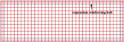
b) Layout of the belt
c) Stress at the bottom surface
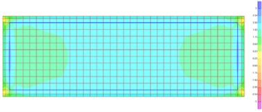
In this paper, the cracks in the MSW incinerator mainly appear at the bottom. A 2-meter wide C45 RC expansion belt with a restriction expansion ratio of 2×10⁻⁴ needs to set at the bottom. 14 %-15 % expanding agent needs to be added to the RC expansion belt, and 10 %-12 % expansion agent needs to be added to the concrete on both sides. The dense-hole wire gauze is arranged on both sides of the RC expansion belt. The whole construction process can be carried out continuously. Because of the more expansion agent of RC expansion belt, a large expansion rate is generated. However, the concrete on both sides has less expands. This creates a large expansion zone in the middle and a small expansion zone on both sides [10]. Fig. 5(a) is the design diagram of expansion reinforcing belt and Fig. 5(b) is the layout of the expansion reinforcing belt. It can be seen from Fig. 5(c) that in the winter condition, the stress in the longitudinal direction of the bottom of the incinerator is at most 2.02 MPa.
6. Conclusions
By analyzing the temperature stress of the MSW incinerator model, it can be found that:
1) The existence of the surrounding soil layer will affect the stress distribution of bunker, mainly at the bottom surface and the portion at ground level.
2) Due to the thermal expansion and contraction, the MSW bunker is pressed during the heating process, which is safe; in the process of cooling, there will be excessive tensile stress at the bottom surface, and reinforcement measures need to be considered.
3) Applying an expansion reinforcing belt to the region with large tensile stress can effectively reduce the maximum tensile stress.
References
-
Mao G. R., Zhang Y. X., Wen W., He D. R. Analysis of municipal solid waste treatment status and the feasibility of incineration method in China. Urban Studies, Vol. 17, 2010, p. 12-16, (in Chinese).
-
Madsen O. H. New technologies for waste to energy plant. 4th International Symposium on waste Treatment Technologies, 2003.
-
Nature Conservation and Nuclear Safety. Waste Incineration – a Potential Danger? Bidding Farewell to Dioxin Spouting. Federal Ministry for the Environment, 2005. http://www.seas.columbia.edu/earth/wtert/sofos/Waste_Incineration_A_Potential_Danger.pdf.
-
Zeng Z. W., Yu Z. P., Hu S. G. Disposal and development of household waste in ‘waste free city’. World Environment, Vol. 2, 2019, p. 46-49, (in Chinese).
-
Liu J. B., Lv Y. D. A direct method to analyze the dynamic interaction between structure and foundation. China Civil Engineering Journal, Vol. 1998, Issue 3, 1998, p. 55-64, (in Chinese).
-
Gu Y., Liu J. B., Du Y. X. Three-dimensional uniform viscoelastic artificial boundary and equivalent viscoelastic boundary element. Engineering Mechanics, Vol. 2007, Issue 12, 2007, p. 31-37, (in Chinese).
-
Liu J. B., Wang Z. Y., Zhang K. F., Pei Y. X. Three dimensional finite element analysis of foundation of large power machine under soil-structure interaction. Engineering Mechanics, Vol. 2002, Issue 3, 2002, p. 34-38+49, (in Chinese).
-
Liu J. B., Wang Z. Y., Du X. L., Du Y. X. The fluctuation problem of three dimensional viscoelastic artificial boundary in time domain. Engineering Mechanics, Vol. 2005, Issue 6, 2005, p. 46-51, (in Chinese).
-
Wu L. Analysis of Ambient Temperature Stress and Crack Control of Ultra-Long Basement Wall. M.S. Thesis, Shenyang Jianzhu University, Shenyang, China, 2004, (in Chinese).
-
Chai L. R. Research on the Design Method of Temperature Stress and Expansion Strengthening Belt of Concrete Frame Structure. M.S. Thesis, Nanchang University, Nanchang, China, 2006, (in Chinese).
About this article

