Abstract
The injector body is an important component of the injector. In order to ensure the reliable operation, the finite element analysis made in ANSYS Workbench is used to simulate and analyze the stress and the fatigue strength of the injector body provided that the fuel loads and unloads instantly. The analysis shows that the stress concentrations of the injector body exist at the entrances of the split ports. It is found that the stress can be reduced, and the fatigue strength of the injector body can be increased by rounding. Finally, the relationships between the fillet radius and the stress concentration and fatigue strength are obtained. Ensure the fatigue strength of the injector body meets the requirement.
Highlights
- Use Fatigue Tool in ANSYS Workbench to simulate the fatigue strength of the injector body under the maximum stress.
- Create fillet at the entrances of the split ports, which will make the fuel inside the injector body flows more gently.
- The radius of fillets have important influences on the fatigue strength of the injector body.
1. Introduction
As an important component of the fuel supply system for diesel engine, its performance has an important impact on the reliability of the diesel engine [1]. The main function of the injector is to atomize high pressure diesel and spray it into the combustion chamber and mix it with air to burn, which is the core of the diesel engine. The main components of the diesel injector include: injector body, solenoid valve, control room, control piston, needle valve, etc. [2].
As an important part of injector, injector body is one of the core components of the injector. The injector body is a thin-walled component, and fuel flows inside it so it suffered from an extreme pressure. The injector body is also processed with long and thin holes, which have important impacts on the fatigue strength and fatigue life of the injector body. So, it is significant to analyze the fatigue strength of injector body. Use ANSYS Workbench to make analysis of the stress of the injector body if the fuel loads and unloads instantly. According to the results, a method it is to be proposed to increase the fatigue strength of the injector body.
2. Model and simulation method
2.1. Physical geometry and mesh
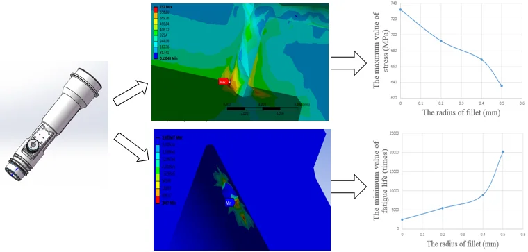
The injector body has one fuel inlet. The fuel enters the oil chamber after passing through the oil inlet. After that the fuel divided into three parts flowing into three split ports. A physical model of the injector body is shown in Fig. 1.
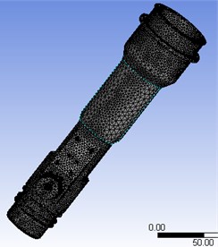
The three-dimensional model of injector body is imported into ANSYS Workbench and is meshed, choosing another size for each part and the generation of face mesh with refinement on contact surface, the generated mesh is shown in Fig. 2. The statistical result is that the number of nodes is 341,962, and the number of elements is 231,381. The average elements quality is 0.79, and it is higher than 0.7; that proves that the quality of the elements is good.
Fig. 1Geometry of injector body
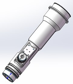
Fig. 2Mathematical model of injector body
2.2. Preset simulation condition
When the fuel loading and unloading instantly, the pressure will increase to 180 MPa at 7.1 s suddenly and the pressure of 180 MPa will be applied to the injector body. Then the pressure will decrease quickly, the period is 470.15 s. The Analysis Setting is made according to the period, loading the specified data to the Transient Structural module. Except the pressure of fuel, the injector body also have the bolt preload of 46500 N.
At the same time, constraints are added to the injector body model, and the Displacement is set as the type of constraints. The purpose is to limit the displacement of the injector body on some directions.
2.3. Material definition
Due to a high demand to fatigue strength of the fuel injector body, the material of injector body is proposed to be 20Cr steel, which has excellent processing properties. This grade of steel has high hardenability and wear-resistant surface after carburizing and quenching [3]. And the steel becomes mostly not prone to deformation after quenching. Some physical properties of 20Cr steel are shown in Table 1.
Table 120Cr steel physical properties
Density (kg/m3) | Elasticity Modulus (MPa) | Poisson’s ration | Yield Strength (MPa) |
7850 | 207E+05 | 0.25 | 850 |
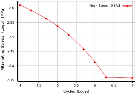
In order to get the fatigue life, it is also required to provide a S-N curve of 20Cr steel, according to experiment [4], and this S-N curve is shown in Fig. 3.
Fig. 3S-N curve of 20Cr steel
3. Simulation and discussion
3.1. Analysis of stress
The Transient Structural is used in ANSYS Workbench to analyze the stress of the injector body provided that the fuel loads and unloads instantly. ANSYS uses the fourth strength theory to calculate the stress. The fourth strength theory is also called as the distortion energy theory. The expression is that the yield of material is caused by the change of energy density. This theory assumes that the change of energy density caused by deformation is the factor that causes material yield. This is to say, no matter what the stress state is, as long as the change of energy density caused by deformation at a point in the component reaches the fatigue limit value of the material that will produces the plastic yield. The fourth strength theory formula is:
The result shows that the injector body suffers the max stress at 7.1 s, at that time the equivalent stress distribution is provided inside the injector body as shown the Fig. 4.
Fig. 4Equivalent stress distribution slice and partial detail at 7.1 s
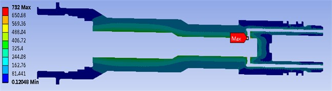
a)
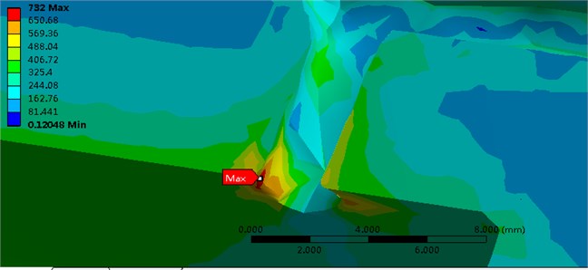
b)
The figure shows that the maximum equivalent stress value is 732 MPa and occurs at the entrances of three split ports. It can be seen the stress concentrations exist in the entrances of three split ports.
3.2. Analysis of fatigue strength
The S-N curve is a material fatigue curve which indicates the relationship between number of stress cycles and figure limit. The stress after cycles, the maximum stress cannot make the fatigue failure to the material which called as fatigue limit stress. The figure curve can be divided into two parts: one is the finite life region and the other is the infinite life region. The finite life region means that when the strain level of the components is lower or equal to the fatigue limit, the stress cycles can exceed that means the components will not have fatigue damage.
The relationship between the variable stress and cycle number under the stress which will lead to the fatigue damage is as follows:
This equation is called as fatigue curve equation, where is the fatigue limit stress of under the finite region; where N is the cycle number fit the , m is the index related to the material, is the constant from experiments.
Fatigue Tool is used in ANSYS Workbench to simulate the fatigue strength of the injector body under the maximum stress. The stress concentration parts will be discussed carefully. The fatigue life of the entrances of three split ports should be discussed separately, but the partial detail figure of fatigue life is shown in Fig. 5.
Fig. 5Fatigue life partial detail figure

The figure shows that the minimum cycle number, which exists at the entrances of split ports, is 2487. Because the fuel loads and unloads instantly, and this always happens only during the startup of the diesel engine’s operation, the cycle number 2487 can meet the requirement. However, in order to increase the fatigue life and extend the using time, it is required to reduce the maximum stress of the stress concentration.
3.3. Structural modification
It is known from the above, although the fatigue strength can meet the requirement, the maximum value of stress concentration is large [5]. In order to reduce the stress concentration, it is required to modify the structure of the injector body.
Fig. 6Modified structure model partial detail figure
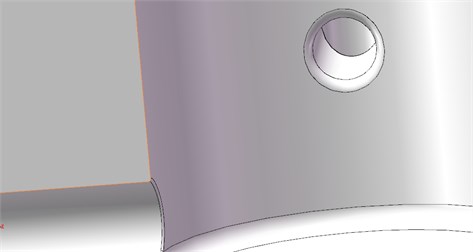
One of the methods to reduce the stress concentration consist in creating a fillet at the entrances of split ports [6], which will make the fuel inside the injector body flows more gently. So, the maximum value of stress can be reduced. This is a new method to reduce the stress concentration of the injector body. The model of the modified structure is shown in Fig. 6.
Take the radius of fillet is 0.4 mm as an example, after creating fillets, the analysis results are shown in Fig. 7.
Fig. 7Stress and fatigue strength figure after creating fillets
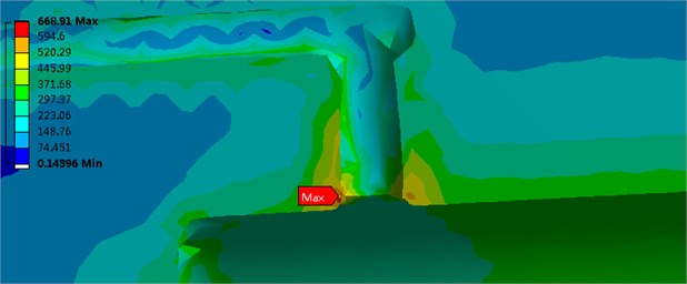
a)
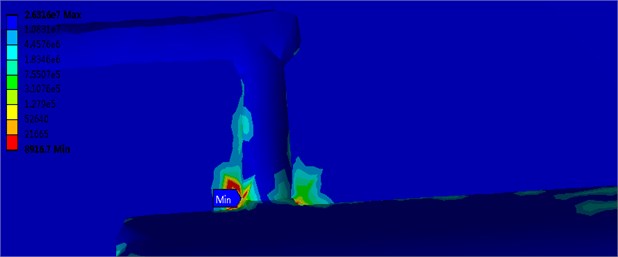
b)
As shown in the figure, after creating the fillets, the stress concentration is also available, but the maximum value of stress declines obviously, and the fatigue strength is also increasing.
The radius of fillets has important influences on the fatigue strength of the injector body. So, if creating different radiuses of fillet to simulate the stress and the fatigue strength to prove whether different radius of fillet will affect the stress and the fatigue strength. The simulation results are shown in Table 2.
Table 2Stress and fatigue life with different radiuses of fillets
Radius of fillets (mm) | Maximum stress (MPa) | Minimum stress (MPa) | Minimum fatigue life (times) | Conformance with strength requirement |
0 | 732.00 | 0.12048 | 2487.0 | Yes |
0.2 | 692.57 | 0.23923 | 5449.8 | Yes |
0.4 | 668.91 | 0.14396 | 8916.7 | Yes |
0.5 | 635.43 | 0.10838 | 20184.0 | Yes |
As shown in the above table, with the development of the fillet radius, the maximum value of stress decreases. However, due to the size of injector body itself the radius of fillet could not increase infinitely, so when the radius of fillet is 0.5 mm, it could reduce the maximum value of stress concentration and enhance the fatigue life well. The relationship between the radius of fillet and the maximum value of stress, and the relationship between the radius of the circular beads and the minimum fatigue life are shown in Fig. 8.
Fig. 8Relationship between radius of circular beads and stress, and fatigue life
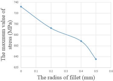
a)
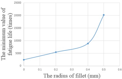
b)
4. Conclusion
ANSYS Workbench is used to analyze the stress and the fatigue strength of the injector body, getting the results of the maximum value of stress and the minimum value of fatigue strength that if the fuel loads and unloads instantly. It was also used to find the stress concentration. On this basis, the structure is modified; by creating fillets, and finding the relationship between the radius of fillet and the maximum value of stress as well as the relationship between the radius of circular beads and the minimum fatigue life. It shall be ensured that, when the radius of fillet increases, the maximum value of stress of the injector body shall decline, and when the radius of fillet increases the minimum value of fatigue life of the injector body shall increase, this is a new method to reduce the stress concentration of the injector body which apply the data support to modify the structure of the injector body.
References
-
Liu Ju Yan, He Zhi Xia, Wang Qian, Huang Yan Long Finite element analysis of high-pressure common-rail injector body. 2nd International Conference on Manufacturing Science and Engineering, Vol. 199, Issue 200, 2011, p. 579-582.
-
Wu Xin Ying, Ouyang Guang Yao, Li Yu Xue Design and optimization of injector structure in diesel engine based on iSIGHT platform DOE methods. International Conference on Materials and Products Manufacturing Technology, Vol. 335, Issue 336, 2011, p. 1376-1380.
-
Chen Ying Chun, Zhang Shi Min, et al. Design of a new experimental coiled tubing injector. IEEE International Conference on Mechatronics and Automation, 2013, p. 727-731.
-
Liu Gan Hua, Yan Hong Zhi Experimental study on static and dynamic mechanical behavior of 20CrMnTi gear steel. International Conference on Measuring Technology and Mechatronics Automation, Vol. 2, 2010, p. 191-195.
-
Shen Xiao Jun, Wang Cheng, et al. Effects of oblique laser shock processing on rotary bending fatigue of aero-engine fan shaft. Infrared and Laser Engineering, Chinese Society of Astronautics, Vol. 44, 2015, p. 3548-3553.
-
Yang Quan Quan, Gao Chun Fa, Chen Wen Tao Stress concentration around a circular hole in a functionally graded material finite plate. Symposium on Piezoelectricity, Acoustic Waves, and Device, 2011, p. 167-177.
About this article

The authors gratefully acknowledge the support from the National Natural Science Foundation of China (Grant No. 51574161).
