Abstract
Phasor Measuring Units (PMU) is considered as a feasible alternative for power system data communication and for the preparation of smart grid. To operate multiple PMUs in stable mode, synchronization is a much essential procedure. After examining the concise literature survey on topical PMU applications, this paper step ahead by considering prevailing objectives such as: extension of network topology and PMU calibration considering bias errors. The appropriate deployment of PMUs and intimidating situation influence the reliance on physical configuration. Hence, it is obligatory to extend the topology of the networks. Also, calibrating the PMUs in a definite trail is crucial as the phasor measurements will be corrupted by bias error. This paper proposes a novel framework for bias error detection and calibration of PMU while expanding the topology network. With a whale optimization algorithm based method to improve the accuracy of PMU measurements for enhancing power system state estimation, monitoring and control operations. Case studies on the standard test systems have been conducted to test the efficacy of the intended tool.
Highlights
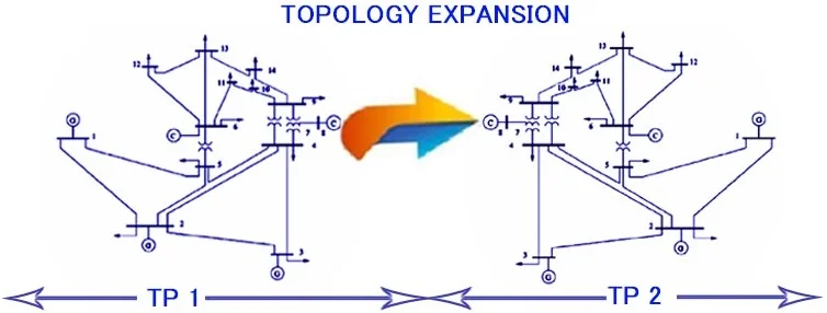
- A new topology expansion observability based PMU placement technique is proposed.
- Phasor measurement unit and wide area monitoring systems.
- Phasor measurement unit calibration considering bias errors for system integrity protection.
- Deployment of phasor measurement unit is minimized and maximizes the coverage.
1. Introduction
1.1. Calibration of PMU with topology expansion
The state estimation of power system provides approximate computation for all metered and unmetered quantities. The main intend of SE is to sort out errors due to model approximations and measurement inaccuracies. A state estimator is designed to process the real time meter readings, to handle all the uncertainties and to produce a real time reliable database in order to view the system status. The perspectives of power system SE can be categorized as instrumentation based and tool-based. These perceptions are endorsed to establish a reliable and comprehensive real-time database [1]. Conferring to the assessment of SE, the following aspects will be the future trend.
• Wide-area power system by formation of multiple zones with interconnection between each network.
• Real-time SE algorithm using time stamped GPS Technology.
• Finally, the expansion of topology to get complete observability.
PMU is a device used to monitor the state of power systems and control applications. So it is the inevitable tool in smart grids. The PMU data is highly accurate but their measurements are not effectuated sometimes due to various abnormal conditions arise in the system. The data quality issues experienced by PMUs can be addressed by calibration. PMU calibration schemes can be performed as offline testing and using mathematical models.
The offline testing/calibration method entails expert equipment/system and also instrumentation channel errors cannot be replicated. The mathematical model checks the loyalty of the system. The influence of the exactitude of PMU devices focuses on algorithms proposed the estimation of dynamic Phasor, and interpretations their enactments under various conditions [2]. The impacts of these sources are summarized into: random and bias error. Random errors are arithmetical vacillations of the measurements because of the meticulous limitations of the PMU device that is avoided by measuring through statistical mean. The bias error is reproducible inaccuracy and is consistent. It is difficult to estimate and analyzed statistically. Calibration of multiple PMU is integrated into higher-level topologies for effective measurements. The complexities of these topologies vary from full network systems over a geographical area.
1.2. Research hiatus
Calibration of PMU devices and estimating the conditions of the system are the major concerns in modern power systems. As mentioned formerly, a large system to monitor will be the potential advancement to explore the SE process, precise calibration of these PMU devices is required. Also, the potential concert of PMU will be mislaid due to the existence of biased error. Therefore, it is apparent that accuracy should be assured for the performance of smart grid. Taking the aforementioned concern, an optimal approach with the objective to ensure maximum accuracy of the network is unified with PMU placement problem.
1.3. State-of-the art work
The bias error occurred while calibrating the PMUs and extending the topology of different test systems is considered as the major pressing problems in SE. A recent survey on the problem of calibrating the PMUs precisely with bias error embraces a widespread procedure to obtain the phasor representation of an input signal and applying discrete transform to compute the consequent Phasor [3]. The synchrophasor based calibration framework has been developed considering overall bias error [4]. However, it depends on a particular model for measuring the synchrophasors that is implemented in a PMU. Perhaps, a comprehensive study on finding the appropriate PMU locations to ensure minimum estimation error and the correctness of it [5]. The estimation process for the intention of minimizing the impact of measurement error [6]. The foremost drawback is that a two terminal transmission line model is utilized. An augmented method for voltage transformers calibration using synchrophasor measurement of ratio and bias errors is recommended [7]. The PMU calibrations are stipulated for enhancing the correctness of PMU measurements [8]. But due to less accuracy, it may be complicated to implement the PMUs across a wide area network. An algorithm has been developed to calculate calibration factors (CFs) using a measuring model [9]. Conversely, it is observed that the level of calibrations is increased. With the aforementioned difficulties that crafts traceable magnitude and phase calibration for ac signals, active and passive components and extend the automatic finding and correcting the bias error have been analysed [10-12]. Despite the facts, the models detailed provide an iterative based elucidation. The latter work integrates synchronized measurement calibration process causing several distinct sources of errors [13]. The calibration of the measurement problem and secondary of it are detailed [14, 15]. Nevertheless, implementation and performance details are not endowed.
In correlation with the above model, an instrument transformer for calibration of ratio and factors of phase angle has been propounded [16]. But this method is used for multiple sets of measurements. It is detailed for calibrating the PMUs [17], but it requires multiple data for reducing the error. The algorithm of fault location is entrenched to investigate the PMU response error [18]. Nevertheless, the technique has integrated the calibration of error by placing the PMUs. Testing the function of PMUs and observation of their consistent accuracy have been demarcated [19]. However, such estimation produces a mismatch between the measured phasor and the actual phasor. The parameter error identification method detects and identifies measurement errors by placing the PMUs at appropriate locations [20]. Conversely, the tactic does not contemplate the assessment of large scale systems. An approach for PMU placement considering both existence and lack of conventional measurement is presented [21]. In addition, a methodology for estimating the uncertainties based on the WLS state estimation related to the PMU measurements are promulgated [22]. Yet, the approach contemplates those measurements which are not free from errors. An approach combines the analysis of observation and detection of bad data into a single framework to solve PMU placement problem for SE [23]. It is observed that these algorithms have not focused on calibration of PMUs. An on line error correction method to precise both the resonance error and saturation error is suggested [24]. Moreover Using PMUs the linear estimation is presented and the transmission of line parameter is identified [25]. Furthermore, microprocessor based phasor measurements [26], with necessary cradles of information for predicting the instability of the system and perceiving the uncertainties in analog measurements is indorsed [27]. In all the circumstances that has been enumerated in the chronological order, PMU calibration has not been taken in the interpretation. Even though testing and calibrating the PMUs with the TESLA 3000 DRF using Doble F6150 has been assimilated [28], only a multi time framed recording system is used for monitoring electric power systems. A MICA based algorithm is suggested [30] for OPP in case of normal and abnormal conditions. According to the above details, the concept of deploying PMUs considering topology expansion, calibration of PMUs with bias error is mislaid in the above literatures. Hence, this article highlights a significant interest in extending the topology of the network and calibrating the PMUs accurately with consideration of bias error.
1.4. Motivation and objectives
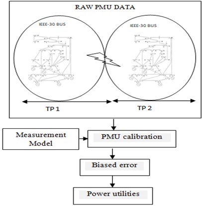
Referring Table 1, there has been significant reports detail the PMU calibration and finding the bias error. The bias error will be exposed only when there is delay from the output of transducer to the input of PMU device. For efficient monitoring and various control applications PMU device can be used in which the bias error is incorporated to correct the PMU data. The primary focus is on the issue of topology extension based on the set of performance evaluation metrics. To the knowledge of authors, there is no previous study (Table 1) on this subject extending the topology of test systems, calibrating the PMU device and identifying the bias error (in a single framework). The proposed methodology is clearly deliberated in Fig. 1.
1.5. Article organization
This paper is arranged as follows. Section 2, establishes a mathematical model to incorporate their objectives. In Section 3, the algorithm for solving the proposed model using WOA is conferred. In Section 4, the topology extension for different test systems and normalized error measurement considering various scenarios has been conferred. Finally, in Section 5 conclusion of the paper and future work has been presented.
Fig. 1Proposed calibration of PMU for topology expansion
2. Problem description
PMUs especially application and system model reliant. Algorithms that are deliberated based on one system model typically do not show similar effectiveness when they are applied on another system model without amendment. Thus, define the system model before presenting any algorithm/architecture is very necessary.
2.1. Formulation of normalized PMU error
True value of error is considered as the decisive factor for the purpose of estimating PMU measurements. The value of error is a gauge between true value and measured value which is represented in terms of magnitude. When the amount of error is minimized the utmost efficiency of the SE is guaranteed. The accuracy of estimation is calculated as:
For the purpose of formulating the actual level of error [5], is espoused because it considers enhancing the accuracy of estimation as one of the major rationale for deploying the PMUs where, is the number of PMUs that are to be in position in the power system of buses ().
2.2. Observability-constrained PMU
The intention of extending the topology of the network buses is to discover the rigid structure that fits into the province. For the class of over changing, complex, and common world problems, the fundamental subject discriminating countervail nature of our prevailing the current search algorithms could be counterproductive to growing explorative behaviour. In addition, it should satisfy the boundary constraints and it should have prescribed number of PMUs. After topology extension, the dilemma becomes:
The optimization problem that minimizes the objective function given in Eq. (2) should satisfy the constraint Eq. (3). Therefore, as a result of placing less quantity of PMUs while extending the topology of PMUs, the value of error will reach a minimum value which in turn leads to maximum efficiency.
Table 1Resent reports and proposed
Authors | Year | Methods | Objectives | ||
Calibration | Bias error | Topology extension | |||
Zhong and Abur [14] | 2005 | Identification of calibration models and estimation of the model parameters along with the system states | ✓ | No reports | |
Zhou, et al. [15] | 2006 | The conventional state estimator software based state estimation designed to develop the initial estimators and integrate the information provided by PMUs | ✓ | ||
Liao and Kezunovic [6] | 2007 | A method for fault location to make all the measurements available and minimize the impacts of measurement errors | ✓ | ||
De La Ree, et al. [3] | 2010 | The PMU and WAMS technology that are used to measure the Phasor and its use in power system | ✓ | ||
Zhang, et al. [13] | 2011 | A calibration method is presented in order to match the PMU measurements and operations planning transmission-line impedance data | ✓ | ||
Vanfretti, et al. [12] | 2011 | An approach for synchronized phasor measurement-based SE, which can perform phasor angle bias correction | ✓ | ||
Shi, et al. [9] | 2012 | Detection and adjustment of errors in PMU measurements for the purpose of calibration | ✓ | ||
Zhou, et al. [16] | 2012 | This method is used for calibrating the instrument transformers’ ratio and phase angle correction factors, and to utilize the PMUs | ✓ | ||
Castello, et al. [2] | 2012 | The consequence of Phasor evaluation models on the correctness of the devices focus on proposed algorithms | ✓ | ||
Pirret [8] | 2012 | Performance limits for PMU test and calibration | ✓ | ||
Tang, et al. [10] | 2013 | Magnitude and phase calibration for AC signals under steady-state and dynamic conditions | ✓ | ||
Trinchera, et al. [11] | 2017 | The method used to characterize the amplifiers and to compare the input and the output of each amplifier, and to precise phase calibration of functional elements | ✓ | ||
Wang, et al. [4] | 2018 | A novel data mining based synchrophasor measurement calibration framework which detects and correcting bias errors | ✓ | ||
Shahriar, et al. [5] | 2018 | The adapted formulation of WLS to run the assessment correctly with mixed measurement | ✓ | ||
Proposed | Error biased PMU calibration for system integrity protection | ✓ | ✓ | ✓ | |
3. Error biased PMU calibration for topology expansion
3.1. Necessity of optimal tool
The foremost intend of the projected technique of topology expansion is to compute the minimum locations and coverage of PMUs that ensure complete observation of the system. This kind of natural extension facilitates to extort the most significant locations which in turn enhance the decision-making process. Thus, it is apparent that the process of topology expansion provides more valuable information for which a minimum optimal location of PMU is required. Concurrently, for handling the non-linear constraint in the projected model an efficient algorithm must be explored in an efficient way. Therefore, the optimal locations of PMU are determined using whale optimization algorithm.
Fig. 2PMU placement using WOA for topology expansion
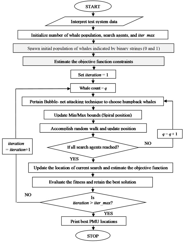
The reason behind choosing this swarm-based technique is that most of the mathematical models are just a generalization of the real problem and it does not embrace the entire facets of the proposed problem whereas, whale optimization algorithm (WOA) is able to decipher the optimization problems with curtailing the hunting behaviour of humpback whales. Furthermore, WOA leads to rapid discovery of good solutions [29]. Therefore, instead of mathematical models it is necessary that a swarm based meta-heuristic technique is essential for solving the process of topology expansion. The flow chart of computation of WOA is detailed in Fig. 2.
3.2. Calibration and normalized error
For the intention of ensuring accuracy in PMU, conventional measurements are employed. Calibration is considered as one of the significant factors for the reason of generating highly accurate measurements. The consequent PMUs must be calibrated with the aid of CFs. Unanimously, two varieties (rectangular and polar coordinates) of formulations and two methods (online and offline) are used to estimate the corresponding CFs. In this paper, the CFs evaluated using the polar coordinates in offline mode.
There are numerous categories of optimization procedure for estimating the bias error in the precise quantity. In the proposed model the actual error is calculated using Eq. (1) where, the disparity between the value got by measuring and that of actual is alienated by multiplying with the number of network buses (×2). In addition, the biased error (20 % and 50 %) is introduced in the impedances of the corresponding data (Power Systems Test Case Archive – UWEE), for different test systems. By using the real PMU data, the bias errors in the measured phasors can be estimated in offline mode. Moreover, the approach of estimating the bias error does not entail any sort of parameter but, the presence of unbiased arbitrary noise from instrumentation channel the potential performance in the actual field installation cannot be achieved.
4. Simulation and case study demonstration
4.1. Optimizing PMU locations with topology extension for different test systems
This section discovers and crams about extending the topology of different test systems. In reality this is identified as left undone of topologies that are defined. During topology extension it is necessary to consider the aspects such as size and formation of the network, selection of optimal locations, and cost saving. The model of topology extension for the corresponding network is the most vital concern in placement of PMUs. The concept of topology extension can be formed by probabilistic method where each bus randomly designated a binary number (1 or 0). For example, in Table 2 consider the case of IEEE-14, IEEE-30, IEEE-57 and IEEE-118 bus systems where in normal operation without consideration of topology extension 4, 10, 17, 32 PMUs are desired to ascertain full observation of the network. But when the same test systems are extended naturally (×2) then a minimum of 7, 20, 33, 64 PMUs is placed at corresponding buses which does not ensure full system observability. In addition, the coverage provided by the corresponding PMUs will also be large. Therefore, if the network is extended because of increasing patrons then such PMU devices are needed to be calibrated.
Table 2Feasible PMU placement for topology extension
Test system (topology extension) | Minimum number of PMUs | Coverage |
IEEE-14 Bus | 2, 6, 9, 16, 20, 21, 23 | 37 |
IEEE-30 Bus | 2, 4, 6, 9, 10, 12, 15, 19, 25, 27, 32, 34, 36, 39, 40, 42, 45, 49, 55, 57 | 104 |
IEEE-57 Bus | 1, 4, 9, 14, 20, 22, 25, 27, 29, 32, 36, 39, 41, 45, 49, 54, 58, 61, 66, 71, 77, 79, 82, 84, 86, 89, 93, 96, 98, 102, 106, 108, 111 | 139 |
IEEE-118 Bus | 3, 5, 9, 11, 12, 17, 21, 25, 28, 34, 37, 40, 45, 49, 53, 56, 62, 64, 68, 70, 71, 76, 79, 85, 86, 89, 92, 96, 100, 105, 110, 114, 121, 123, 127, 129, 130, 135, 139, 143, 146, 152, 155, 158, 163, 167, 171, 174, 180, 182, 186, 188, 189, 194, 197, 203, 204, 207, 210, 214, 218, 223, 228, 232 | 332 |
4.2. Calibration analysis
4.2.1. Normalized error measurement
Calibration is the way to determine the correct value of the PMU device by comparing the known value of measurements with the value that needs to be calibrated. The method is followed to ensure that the measurements within the IEEE standards. During the first phase of calibration of PMUs, each PMU is placed in the corresponding locations thus compromising the amplitude and phase angle of the measured phasors. The following three scenarios are conversed to exhibit the applicability of the intended PMU data calibration framework.
4.2.1.1. Scenario 1: using authentic PMU data
The ameliorated eventuality as delineated in Tables 3 and 4 consists of voltage (Magnitude), angle (Degree) and aggregate vector erroneousness for IEEE-14 and IEEE-30 bus systems. In this scenario, the bias error is not incorporated in the impedance references, i.e., only real PMU data are integrated. The magnitude measurement error in this scenario is much lesser when compared to other two scenarios. It can be seen from the Tables 3 and 4 and from the corresponding Fig. 3 and 4 that the true bias error reaches zero for some of the buses in both the test systems. For example, the IEEE-14 bus system (Table 3) shows that the magnitude difference in 2, 3, 6 and 8 will be zero. The true errors are within the limit. Therefore, by using PMU data it is clear that the buses will not become much sensitive and the erroneousness of the instrumentation channels can be corrected at this phase.
Table 3Bias error identification for IEEE-14 bus system
Bus No. | Voltage (Mag.) | Angle (Deg.) | Error |
1 | 1.031 | 0.000 | 1.036×10⁻³ |
2 | 1.045 | –4.986 | 0 |
3 | 1.010 | –12.729 | 0 |
4 | 0.971 | –9.895 | 1.4×10⁻⁵ |
5 | 0.982 | –8.183 | 6.5×10⁻⁶ |
6 | 1.070 | –14.221 | 0 |
7 | 0.995 | –14.631 | 4.6×10⁻⁶ |
8 | 1.090 | –13.361 | 0 |
9 | 0.970 | –17.180 | 1.02×10⁻⁵ |
10 | 0.968 | –17.542 | 6.6×10⁻⁶ |
11 | 0.988 | –17.298 | 1.2×10⁻⁵ |
12 | 0.996 | –18.001 | 1.3×10⁻⁵ |
13 | 0.986 | –18.059 | 1.35×10⁻⁵ |
14 | 0.950 | –19.026 | 1.1×10⁻⁵ |
Fig. 3Comparison of bias error for IEEE-14 bus system
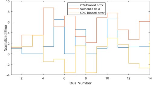
Fig. 4Comparison of bias error for IEEE-30 bus system
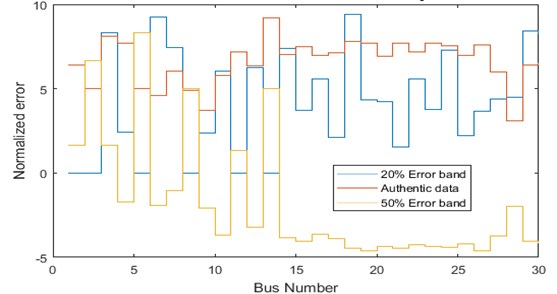
Table 4Bias error identification for IEEE-30 bus system
Bus No. | Voltage (Mag.) | Angle (Deg.) | Error |
1 | 1.060 | 0.0000 | 0 |
2 | 1.043 | –5.487 | 0 |
3 | 1.022 | –8.004 | 8.3×10⁻⁶ |
4 | 1.013 | –9.661 | 2.4×10⁻⁶ |
5 | 1.010 | –14.371 | 0 |
6 | 1.012 | –11.398 | 9.23×10⁻⁷ |
7 | 1.003 | –13.150 | 7.45×10⁻⁶ |
8 | 1.010 | –12.100 | 0 |
9 | 1.051 | –14.384 | 0 |
10 | 1.044 | –16.024 | 6.02×10⁻⁶ |
11 | 1.082 | –14.394 | 0 |
12 | 1.057 | –15.242 | 0 |
13 | 1.071 | –15.242 | 0 |
14 | 1.042 | –16.131 | 0 |
15 | 1.038 | –16.228 | 0 |
16 | 1.045 | –15.830 | 0 |
17 | 1.039 | –16.188 | 2.13×10⁻⁶ |
18 | 1.028 | –16.824 | 0 |
19 | 1.025 | –17.052 | 4.36×10⁻⁶ |
20 | 1.029 | –16.852 | 4.24×10⁻⁶ |
21 | 1.032 | –16.468 | 1.52×10⁻⁶ |
22 | 1.033 | –16.415 | 0 |
23 | 1.027 | –16.612 | 0 |
24 | 1.022 | –16.830 | 7.3×10⁻⁶ |
25 | 1.019 | –16.424 | 2.2×10⁻⁶ |
26 | 1.001 | –16.842 | 3.64×10⁻⁶ |
27 | 1.026 | –15.912 | 4.4×10⁻⁶ |
28 | 1.011 | –12.057 | 4.5×10⁻⁶ |
29 | 1.006 | –17.136 | 8.4×10⁻⁷ |
30 | 0.995 | –18.015 | 8.2×10⁻⁶ |
4.2.1.2. Scenario 2: 20 % error band
In this scenario an error of 20 % is incorporated for impedances in the corresponding data and the results given in Tables 5 and 6. It can be perceived from Tables 5 and 6 and Figs. 3 and 4 that none of the buses in both the test systems (IEEE-14 and IEEE-30 bus systems) has zero as actual error. This procedure indicates that the calibration can also be done remotely at phasor data concentrator. The intent of establishing random errors is not only to resolve which bus is more accurate, but moderately detect and establish the incongruity so that improvements can be done while calibrating the PMUs in corresponding locations.
Fig. 5Error band accumulation for IEEE-14 bus system (bus vs voltage magnitude)
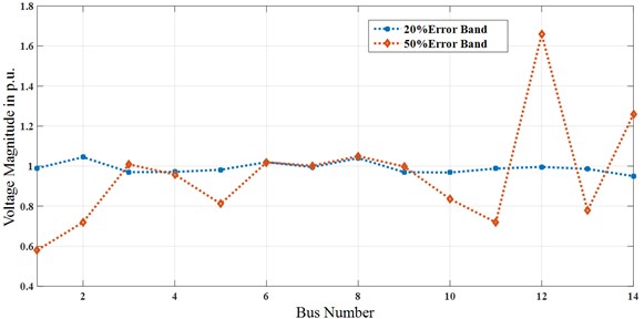
Fig. 6Error band accumulation for IEEE-14 bus system (bus vs error)
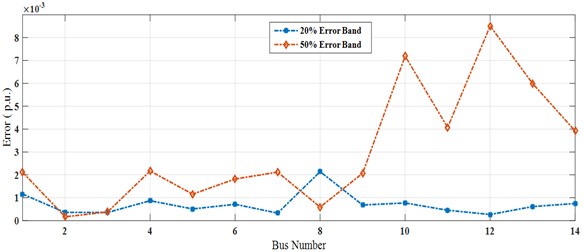
Table 5Error band accumulation for IEEE-14 bus system
20 % error band | 50 % error band | |||||
Bus No. | Voltage (Mag.) | Angle (Deg.) | Error | Voltage (Mag.) | Angle (Deg.) | Error |
1 | 0.99 | 0.000 | 1.16×10⁻³ | 0.58 | 0.000 | 2.11×10⁻³ |
2 | 1.045 | –4.064 | 3.57×10⁻⁴ | 0.72 | –27.13 | 1.67×10⁻⁴ |
3 | 0.970 | –20.920 | 3.57×10⁻⁴ | 1.009 | –17.03 | 3.79×10⁻⁴ |
4 | 0.971 | –17.628 | 8.69×10⁻⁴ | 0.958 | –29.91 | 2.17×10⁻³ |
5 | 0.982 | –11.117 | 5.1×10⁻⁴ | 0.812 | –22.17 | 1.157×10⁻³ |
6 | 1.020 | –18.773 | 7.14×10⁻⁴ | 1.019 | –16.115 | 1.82×10⁻³ |
7 | 0.995 | –19.816 | 3.28×10⁻⁴ | 1.002 | –21.47 | 2.12×10⁻³ |
8 | 1.040 | –19.816 | 2.14×10⁻³ | 1.050 | –26.14 | 5.91×10⁻⁴ |
9 | 0.970 | –22.044 | 6.82×10⁻⁴ | 0.998 | –12.580 | 2.07×10⁻³ |
10 | 0.968 | –22.344 | 7.72×10⁻⁴ | 0.836 | –13.991 | 7.19×10⁻³ |
11 | 0.988 | –20.865 | 4.52×10⁻⁴ | 0.719 | –26.781 | 4.07×10⁻³ |
12 | 0.996 | –21.021 | 2.67×10⁻⁴ | 1.659 | –21.128 | 8.51×10⁻³ |
13 | 0.986 | –22.102 | 6.13×10⁻⁴ | 0.778 | –18.55 | 5.99×10⁻³ |
14 | 0.950 | –24.059 | 7.49×10⁻⁴ | 1.259 | –19.37 | 3.92×10⁻³ |
4.2.1.3. Scenario 3: 50 % error band
In this scenario, the intended model is tested by dealing with big magnitude error. Here, an error of 50 % is added in the corresponding bus impedances and the results given in Tables 5 and 6 and in Figs. 3 and 4 respectively. From Table 5 it is found that the worst case situation occurs when an error of 50 % added to each impedance in the corresponding data and the true bias error will never get minimized to zero. Also, for some of the corresponding buses (in IEEE-14 and IEEE-30 bus) the true error remains negative which in turn indicates that the calibration aspects remain inaccurate. Therefore, when the PMUs are calibrated with large magnitude errors then it will be very difficult to realize the accuracy of such devices. Figs. 5 to 8 shows that the error band accumulation for IEEE-14 and IEEE-30 bus system.
Table 6Error band accumulation for IEEE-30 bus system
20 % error band | 50 % error band | |||||
Bus No. | Voltage (Mag.) | Angle (Deg.) | Error | Voltage (Mag.) | Angle (Deg.) | Error |
1 | 0.996 | 0.000 | 6.4×10⁻² | 0.91 | 0.000 | 2.91×10⁻⁴ |
2 | 0.993 | –24.866 | 5×10⁻¹ | 0.996 | –16.8 | 9.01×10⁻⁴ |
3 | 0.940 | –18.817 | 8.1×10⁻² | 1.036 | –23.7 | 4.67×10⁻⁴ |
4 | 0.935 | –31.527 | 7.7×10⁻² | 0.905 | –34.57 | 8.93×10⁻³ |
5 | 0.960 | –46.761 | 5×10⁻¹ | 0.911 | –27.03 | 7.88×10⁻⁴ |
6 | 0.966 | –39.828 | 4.6×10⁻² | 1.278 | –37.18 | 6.54×10⁻³ |
7 | 0.943 | –45.124 | 6.04×10⁻² | 0.917 | –41.29 | 3.03×10⁻³ |
8 | 1.010 | –43.914 | 4.9×10⁻² | 1.1894 | –28.02 | 6.78×10⁻⁴ |
9 | 1.014 | –44.505 | 3.7×10⁻² | 1.0916 | –33.047 | 7.16×10⁻³ |
10 | 0.986 | –48.062 | 5.8×10⁻² | 1.002 | –45.9 | 1.53×10⁻³ |
11 | 1.082 | –44.505 | 7.2×10⁻² | 0.958 | –43.18 | 4.42×10⁻³ |
12 | 0.994 | –44.649 | 6.33×10⁻² | 1.0018 | –52.30 | 3.18×10⁻⁴ |
13 | 1.071 | –44.649 | 9.2×10⁻¹ | 0.993 | –50.93 | 4.86×10⁻⁴ |
14 | 0.972 | –47.182 | 7.04×10⁻² | 0.987 | –54.09 | 2.15×10⁻³ |
15 | 0.963 | –48.044 | 7.47×10⁻² | 1.015 | –56.71 | 7.92×10⁻⁴ |
16 | 0.975 | –46.875 | 6.96×10⁻² | 1.029 | –50.06 | 5.17×10⁻⁴ |
17 | 0.968 | –48.394 | 7.11×10⁻² | 1.36 | –46.037 | 3.17×10⁻⁴ |
18 | 0.950 | –49.836 | 7.79×10⁻² | 0.983 | –59.178 | 3.84×10⁻³ |
19 | 0.948 | –50.646 | 7.72×10⁻² | 0.937 | –58.27 | 2.53×10⁻⁴ |
20 | 0.960 | –49.767 | 6.92×10⁻² | 0.9916 | –63.89 | 1.99×10⁻³ |
21 | 0.955 | –50.158 | 7.70×10⁻² | 1.40 | –59.11 | 3.87×10⁻³ |
22 | 0.961 | –49.636 | 7.16×10⁻² | 1.005 | –76.78 | 1.12×10⁻³ |
23 | 0.950 | –49.574 | 7.72×10⁻² | 0.994 | –68.93 | 5.66×10⁻³ |
24 | 0.946 | –50.556 | 7.55×10⁻² | 1.38 | –62.37 | 7.81×10⁻⁴ |
25 | 0.949 | –50.278 | 6.98×10⁻² | 1.016 | –70.27 | 7.53×10⁻⁴ |
26 | 0.925 | –51.220 | 7.62×10⁻² | 0.923 | –57.3 | 6.07×10⁻³ |
27 | 0.966 | –49.320 | 5.97×10⁻² | 0.856 | –65.06 | 4.18×10⁻³ |
28 | 0.980 | –43.082 | 3.07×10⁻² | 0.917 | –71.915 | 3.11×10⁻³ |
29 | 0.942 | –51.367 | 6.39×10⁻² | 0.930 | –76.81 | 8.013×10⁻³ |
30 | 0.929 | –52.736 | 6.55×10⁻² | 0.962 | –58.016 | 6.14×10⁻³ |
Fig. 7Error band accumulation for IEEE-30 bus system (bus vs voltage magnitude)
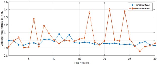
Fig. 8Error band accumulation for IEEE-30 bus system (bus vs error)
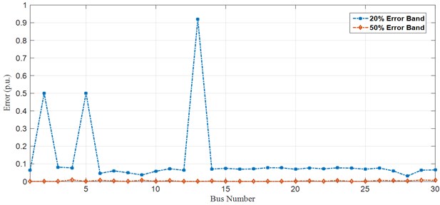
Table 7Comparison of optimal PMU placement between normal condition and topology extension
Test system | Coverage | ||
Normal operating condition | Topology extension | ||
WOA | Ref. [30] MICA | WOA | |
IEEE-14 Bus | 19 | 17 | 37 |
IEEE-30 Bus | 52 | 48 | 104 |
IEEE-57 Bus | 69 | 67 | 139 |
IEEE-118 Bus | 163 | 162 | 332 |
5. Conclusions
The technology of PMUs has come to an end of comprehending its merit for the advancement of reliable grid operations. It is necessary to extend the topology of the system as accuracy becomes the most significant facet of PMU measurement. The present condition of the technologies of art has proven ineffective and is unable to extend the topology of the growing power industries. Therefore, a novel technique of topology expansion is considered in this paper where, even during topology expansion lesser amount of PMUs in normal operation can be placed in optimal locations for ensuring full network observability. In this article, the PMUs are calibrated at every instance when the measurements are taken. This offline calibration effects bias error which is incorporated in the corresponding impedances that can be measured using WOA where, the proposed algorithm is easy to implement for problem solving. The numerical results for corresponding test systems (IEEE-14 and IEEE-30 bus) prove that no inaccuracy has been found out. This method finds out the overall bias error introduced by the instrumentation channels of PMU. Therefore, it is applicable across wide spread of practical applications in power industries for decision making, security and in the groundwork for smart grid. Future work focuses on identifying different topologies on SE and calibrating the PMU devices in deregulated power systems.
References
-
Zhao J., Zhang G., Das K., Korres G. N., Manousakis N. M., Sinha A. K., He Z. Power system real-time monitoring by using PMU-based robust state estimation method. IEEE Transactions on Smart Grid, Vol. 7, Issue 1, 2016, p. 300-309.
-
Castello P., Lixia M., Muscas C., Pegoraro P. A. Impact of the model on the accuracy of synchrophasor measurement. IEEE Transactions on Instrumentation and Measurement, Vol. 61, Issue 8, 2012, p. 2179-2188.
-
De La Ree J., Centeno V., Thorp J. S., Phadke A. G. Synchronized phasor measurement applications in power systems. IEEE Transactions on Smart Grid, Vol. 1, Issue 1, 2010, p. 20-27.
-
Wang X., Shi D., Wang Z., Xu C., Zhang Q., Zhang X., Yu Z. Online calibration of phasor measurement unit using density-based spatial clustering. IEEE Transactions on Power Delivery, Vol. 33, Issue 3, 2018, p. 1081-1090.
-
Shahriar M. S., Habiballah I. O., Hussein H. Optimization of phasor measurement unit (PMU) placement in supervisory control and data acquisition (SCADA)-based power system for better state-estimation performance. Energies, Vol. 11, Issue 3, 2018, p. 1-15.
-
Liao Y., Kezunovic M. Optimal estimate of transmission line fault location considering measurement errors. IEEE Transactions on Power Delivery, Vol. 22, Issue 3, 2007, p. 1335-1341.
-
Pal A., Chatterjee P., Thorp J. S., Centeno V. A. Online calibration of voltage transformers using synchrophasor measurements. IEEE Transactions on Power Delivery, Vol. 31, Issue 1, 2016, p. 370-380.
-
Pirret R. Testing and calibration of phasor measurement units. NCSLI Measure, Vol. 7, Issue 2, 2012, p. 36-42.
-
Shi D., Tylavsky D. J., Logic N. An adaptive method for detection and correction of errors in PMU measurements. IEEE Transactions on Smart Grid, Vol. 3, Issue 4, 2012, p. 1575-1583.
-
Tang Y., Stenbakken G. N., Goldstein A. Calibration of phasor measurement unit at NIST. IEEE Transactions on Instrumentation and Measurement, Vol. 62, Issue 6, 2013, p. 1417-1422.
-
Trinchera B., Serazio D., Pogliano U. Asynchronous phase comparator for characterization of devices for PMUs calibrator. IEEE Transactions on Instrumentation and Measurement, Vol. 66, Issue 6, 2017, p. 1139-1145.
-
Vanfretti L., Chow J. H., Sarawgi S., Fardanesh B. A phasor-data-based state estimator incorporating phase bias correction. IEEE Transactions on Power Systems, Vol. 26, Issue 1, 2011, p. 111-119.
-
Zhang Q., Vittal V., Heydt G. T., Logic N., Sturgill S. The integrated calibration of synchronized phasor measurement data in power transmission systems. IEEE Transactions on Power Delivery, Vol. 26, Issue 4, 2011, p. 2573-2581.
-
Zhong S., Abur A. Combined state estimation and measurement calibration. IEEE Transactions on Power Systems, Vol. 20, Issue 1, 2005, p. 458-465.
-
Zhou M., Centeno V. A., Thorp J. S., Phadke A. G. An alternative for including phasor measurements in state estimators. IEEE Transactions on Power Systems, Vol. 21, Issue 4, 2006, p. 1930-1937.
-
Zhou M., Centeno V., Thorp J. S., Phadke A. G. Calibrating instrument transformers with phasor measurements. Electric Power Components Systems, Vol. 40, Issue 14, 2012, p. 1605-1620.
-
Braun J., Siegenthaler S. Calibration of PMUs with a reference grade calibrator. 29th Conference on Precision Electromagnetic Measurements (CPEM), 2014, p. 678-679.
-
Becejac T., Dehghanian P., Kezunovic M. Impact of the errors in the PMU response on synchrophasor-based fault location algorithms. North American Power Symposium (NAPS), 2016.
-
Braun J. P., Mester C. Reference grade calibrator for the testing of the dynamic behaviour of phasor measuring. Conference on Precision Electromagnetic Measurements (CPEM), 2012, p. 410-411.
-
Zhu J., Abur A. Identification of network parameter errors using phasor measurements. Conference on Power and Energy Society General Meeting, 2009.
-
Abbasy N. H., Ismail H. M. A unified approach for the optimal PMU location for power system state estimation. IEEE Transactions on Power Systems, Vol. 24, Issue 2, 2009, p. 806-813.
-
Chakrabarti S., Kyriakides E. PMU measurement uncertainty considerations in WLS state estimation. IEEE Transactions on Power Systems, Vol. 24, Issue 2, 2009, p. 1062-1071.
-
Gou B., Kavasseri R. G. Unified PMU placement for observability and bad data detection in state estimation. IEEE Transactions on Power Systems, Vol. 29, Issue 6, 2014, p. 2573-2580.
-
Hamrita T. K., Heck B. S., Meliopoulos A. P. S. On-line correction of errors introduced by instrument transformers in transmission-level steady-state waveform measurements. IEEE Transactions on Power Delivery, Vol. 15, Issue 4, 2000, p. 1116-1120.
-
Shi D., Tylavsky D. J., Koellner K. M., Logic N., Wheeler D. E. Transmission line parameter identification using PMU measurements. European Transactions on Electrical Power, Vol. 21, Issue 4, 2011, p. 1574-1588.
-
Thorp J. S., Phadke A. G., Horowitz S. H., Begovic M. M. Some applications of phasor measurements to adaptive protection. IEEE Transactions on Power Systems, Vol. 3, Issue 2, 1988, p. 791-798.
-
Adibi M. M., Kafka R. J. Minimization of uncertainties in analog measurements for use in state estimation. IEEE Transactions on Power Systems, Vol. 5, Issue 3, 1990, p. 902-910.
-
Narendra K., Zhiying Zhang., Lane J., Lackey B., Khan E. Calibration and testing of TESLA phasor measurement unit (PMU) using doble F6150 test instrument. iREP Symposium – Bulk Power System Dynamics and Control – VII, Revitalizing Operational Reliability, 2007.
-
Mirjalili S., Lewis A. The whale optimization algorithm. Advances in Engineering Software, Vol. 95, 2016, p. 51-67.
-
Seyed Abbas Taher, Seyed Mahmoodi, Hamed Aghaamouei Optimal PMU location in power systems using MICA. Alexandria Engineering Journal, Vol. 55, Issue 1, 2015, p. 399-406.
-
Power System Test Case Archive-UWEE. 2014, http://www.ee.washington.edu/research/pstca/.
About this article

