Abstract
With rapidly developing of the distribution networks the rate of the earth fault increases sharply. Aiming to fault location for distribution networks, many techniques are proposed and applied in distribution networks throughout the world. However, until now the technology for precise fault point location has not been successfully implemented in engineering practice. Traveling wave based methods as common techniques are widely applied in transmission line protection for locating fault point. However, these methods face severe challenge in fault location for distribution networks. The main reason is that the intermittent arc fault easily results in failure of detecting inceptive travelling wave and this intermittent arc is a common earth fault in distribution networks compared with transmission networks. In this paper, a simplified distribution line is built by making reference to the two parallel lossless transmission lines system. Then, the intermittent arc effects on traveling wave based method are modeled and discussed. Finally, the reason why these travelling wave based methods are hard to locate fault point precisely is illustrated.
1. Introduction
With rapidly developing of the distribution networks the rate of the earth fault increases sharply. Aiming to fault location for distribution networks prior-art techniques are reviewed and classified. Main advantages and disadvantages of them are summarized. Finally, the future outlook for fault location methods is highlighted. The fault location methods are facing extreme challenges due to high penetration of renewables, the rising number of branched lines and the enlarging area of the distribution system. In terms of the theory of the algorithm, the fault location methods can be classified into five main categories: 1) Physical inspection method, 2) Calculation method, 3) Traveling wave method, 4) Distributed measurement method, 5) Intelligence method.
Physical inspection method is a practical, clear and easy implemented method. In remote areas lines inspection still relays on manpower and most the fault points can be located in the site with the aid of portable devices [1]. However, physical inspection means working with low efficiency in terms of time and human cost. The calculation method such as impedance-based method is also easy to be implemented and less dependent on device configuration [2]. However, the calculation method for fault location is affected by electrical parameters and operation modes of networks. Such as the fault resistance of fault circuit, load and distributed sources have a great influence on the impedance-based method. The traveling wave method is based on traveling wave propagating at high speed and capturing the inceptive wave at terminals of the distribution line.
The traveling wave method is able to estimate the fault location reliably unaffected by the distribution networks operation. The references [3-5] proposed the traveling wave based method based on traveling wave generators or collectors such as partial discharge, electromagnetic time-reversal (EMTR), network topology information and circuit breaker reclosure-generating. However, expensive elements and devices are one of the difficulties the traveling wave method faces for application.
The distributed measurement method is based on measurements from distributed smart metering units. The distributed smart metering units in references [6-9] include voltage measurements, Phasor Measurement Unit (PMU), Feeder Terminal Unit (FTU), Fault Passage Indicator (FPI), Remote Terminal Unit (RTU) and smart grid sensors. The reliability and accuracy of distributed measurement method for fault location mainly benefit from these smart metering units. However due to the limitation of metering devices location, this method is only used for faulty section location or faulty line selection. It is hardly helpful to inspect long and complex distribution lines that the actual fault point cannot be located precisely.
The intelligence method is a hot and emerging technology that has not been fully summarized in prior art references. The intelligence method for fault location with intelligence algorithm is based on utilization of the training dataset and testing dataset obtained from measurement or experiment. The advantages of the intelligence method are that the accuracy and reliability of the fault location are almost not sensitive to the distribution networks parameters and operation modes.
The references [10-13] are based on such as machine learning algorithm, Gaussian Process Regression, artificial neural network, support vector machine, fuzzy self-correction bat algorithm, cause-effect network reverse inference function and fault probability for fault location. However, as the intelligence method is dependent on dataset and the capability of dataset storage is limited, the reliability of this method not meeting the requirement of protection is one of the practical difficulties the intelligence method has. And also, the probabilistic model the intelligence algorithm based on determines uncertainty for fault location
The development of fault location techniques is based on measurement devices upgrading. Current and voltage transformers support calculation method e.g. impedance-based method. Travelling wave sensors support travelling wave method. Distributed metering units support distributed measurement method and intelligence method. However, a number of fault location methods have still not been applied widely in practice due to disadvantages of reliability and accuracy. Since the Ubiquitous Internet of Things in Electricity as a new strategic objective was set by State Grid Corporation of China, modern, advanced and smart sensors have been being installed widely. A large number of data the intelligence algorithm needs will be available easily in the near future. For the distribution networks especially with high PV penetration level, taking advantage of measurements from multiple types of metering devices such as travelling wave sensors, fault passage indicators and phasor measurement units, and at the same time adopting practical intelligence algorithm, the novel method for fault location will be proposed soon. This type of novel fault location method as a part of functionality of distribution automation systems is also one of the directions of the future research and has been increasingly studied.
For the fault location techniques majority are still based on the end measurement, which are inherently limited because of the limited information available from the network. Due to a part of distribution networks is digitalized initially in China relying on existing dispatch automation, equipment condition monitoring, distribution network automation, metering automation and management information system. The waveform data recorded along the lines by distributed metering devices such as fault indicators imply rich fault information, and effective information mining of the data can help grasp the distribution of line faults and make targeted measures in distribution networks. The fault location techniques are intelligentized by increasing distribution network terminals, enhancing data analysis capabilities, and expanding visualization scenarios.
2. Distribution line model
The distribution line model is approximately represented with two parallel transmission lines shown in Fig. 1. Two terminal impedances and as boundary conditions of these two transmission lines are also given.
The Fig. 1 shows that the length of these transmission lines is and the intermittent arc fault occurs at the point (associated to the line longitudinal coordinate ). In addition, the distance of these two parallel lines is and the radiuses of these two lines are and respectively. According to the Fig. 1 the differential circuit of two parallel transmission lines is shown in Fig. 2.
Fig. 1Two parallel transmission lines
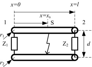
Fig. 2Differential circuit of two parallel transmission lines
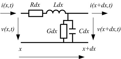
In Fig. 2 the parameters , , and are the resistance, inductance, conductance and capacitance per length of transmission line respectively. According to the law of Kirchhoff, the terminal current and voltage of the differential circuit shown in Fig. 2 can be thus calculated by Eq. (1):
where , are coordinate and time respectively.
In the case of and , the frequency-domain expressions of Eq. (1) can be given by:
where , .
According to Eq. (2) the characteristic impedance is thus calculated by:
At the fault point , the intermittent arc is represented by the combination of the voltage source, and current source, . Finally, the terminal voltage and current of the two parallel transmission lines at two ends are calculated by Eq. (4) and Eq. (5) respectively in the frequency domain:
where:
The intermittent arc fault can be simulated by setting the type of the signal of voltage source and current source. The travelling wave propagated to two ends of the transmission line can be thus calculated.
3. Simulation results
In order to simplify the line model, the lossless transmission line is considered. According to the parameters of transmission line listed in Table 1 the corresponding inductance and the capacitance of this line can be calculated.
Table 1Parameters of transmission line
Symbol | Description | Value | Unit |
Length of transmission line | 30 | m | |
Distance between two parallel lines | 0.2 | m | |
Radius of line 1 cross section | 1.5×10⁻³ | m | |
Radius of line 2 cross section | 1.5×10⁻³ | m | |
Magnetic permeability | 1.3×10⁻⁶ | H/m | |
Dielectric constant | 8.8×10⁻¹² | F/m |
The periodic pulse is used as a current source to simulate intermittent arc at the fault point. The signal of this periodic pulse at the duty of 10 % and the period of 0.4 microseconds respectively is shown in Fig. 3.
The simulation results of terminal current and voltage are shown in Fig. 4 and Fig. 5 respectively. It can be seen clearly from Fig. 4 that the terminal current is smaller than the source current due to the approximate open circuit of this terminal. Conversely, the terminal voltage is significant. Due to the reflection of travelling wave, large groups of wavefront are generated and superimposed. It is hard to reliably detect the inceptive travelling wave in this case. The travelling wave-based method faces severe challenges due to the effect of intermittent arc faults.
Fig. 3The periodic pulse at the duty of 10 % and the period of 0.4 microseconds
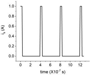
Fig. 4Simulation results of the terminal current in a) the frequency domain, and b) the time domain
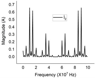
a)
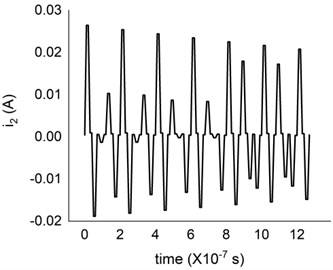
b)
Fig. 5Simulation results of the terminal voltage in a) the frequency domain, and b) the time domain
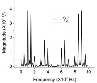
a)
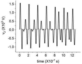
b)
4. Conclusions
1) It is more effective for travelling wave method to detect the terminal voltage of travelling wave than the terminal current of this travelling wave.
2) Due to the effect of intermittent arc faults, it is unreliable to locate the fault point by using inceptive travelling wave-based method.
3) The waveform altitude varies dramatically due to the superposition of traveling wave and the reflection of travelling wave of the open-circuit voltage is larger than the incident wave. The sensitivity of this travelling wave-based method is thus difficult to be set.
References
-
Krasnykh A., Krivoshein I., Kozlov A. Research of single-phase faults in 6-35 kv branched overhead distribution network. International Conference on Industrial Engineering, Applications and Manufacturing (ICIEAM), 2017.
-
Washer M., Maun J. C., Dzienis C., Kereit M., Yelgin Y., Blumschein J. Precise impedance based fault location algorithm with fault resistance separation. IEEE Eindhoven PowerTech, 2015.
-
Wang Z., He S., Li Q., Liu B., Razzaghi R., Paolone M., Xie Y., Rubinstein M., Rachidi F. A full-scale experimental validation of electromagnetic time reversal applied to locate disturbances in overhead power distribution lines. IEEE Transactions on Electromagnetic Compatibility, Vol. 60, Issue 5, 2018, p. 1562-1570.
-
Gaugaz F., Krummenacher F., Kayal M. High-speed analogue sampled-data signal processing for real-time fault location in electrical power networks. IET Circuits, Devices and Systems, Vol. 12, Issue 5, 2018, p. 624-629.
-
Shi S., Lei A., He X., Mirsaeidi S., Dong X. Travelling waves-based fault location scheme for feeders in power distribution network. The Journal of Engineering, Vol. 15, Issue 2018, 2018, p. 1326-1329.
-
Usman M. U., Omar Faruque M. Validation of a PMU-based fault location identification method for smart distribution network with photovoltaics using real-time data. IET Generation, Transmission and Distribution, Vol. 12, Issue 21, 2018, p. 5824-5833.
-
Jin T., Li H. Fault location method for distribution lines with distributed generators based on a novel hybrid bpsoga. IET Generation, Transmission and Distribution, Vol. 10, Issue 10, 2016, p. 2454-2463.
-
Hossan S., Chowdhury B. Data-driven fault location scheme for advanced distribution management systems. IEEE Transactions on SmartGrid, Vol. 10, Issue 5, 2018, p. 5386-5396.
-
Pignati M., Zanni L., Romano P., Cherkaoui R., Paolone M. Fault detection and faulted line identification in active distribution networks using synchrophasors-based real-time state estimation. IEEE Transactions on Power Delivery, Vol. 32, Issue 1, 2017, p. 381-392.
-
Moloi K., Jordaan J., Hamam Y. High impedance fault classification and localization method for power distribution network. IEEE PES/IAS PowerAfrica, 2018, p. 84-89.
-
Moloi K., Yusuff A. A support vector machine based fault diagnostic technique in power distribution networks. Southern African Universities Power Engineering Conference/Robotics and Mechatronics/Pattern Recognition Association of South Africa (SAUPEC/RobMech/PRASA), 2019, p. 229-234.
-
Xie X., Gao Z., Zhang J., Wang Z. A fault location method based on cause-effect network in active distribution network. IEEE 8th Joint International Information Technology and Artificial Intelligence Conference, 2019, p. 837-842.
-
Sowah R. A., Dzabeng N. A., Ofoli A. R., Acakpovi A., Koumadi K. M., Ocrah J., Martin D. Design of power distribution network fault data collector for fault detection, location and classification using machine learning. IEEE 7th International Conference on Adaptive Science and Technology, 2018.
Cited by
About this article

The authors would like to express their thanks to the financial support given by the Science and Technology Project of Yunnan Power Grid Corporation under Grant YNKJXM20180859. Simulation experiment were conducted in Hunan Province Key Laboratory of Smart Grids Operation and Control (Changsha University of Science and Technology), Changsha, as part of a research project on National Key R&D Program of China 2017YFB0902903.
