Abstract
Numerical analysis is conducted on the damage effect of the cylindrical shell under the combined action of fragments and shock waves. Preformed holes are used to simulate the failure effect of fragments. Three different damaged modes are obtained in the numerical simulation, namely, local depression deformation, coupling of local depression deformation and global deformation, coupling of global deformation and local penetration. When the shell is subjected to large explosive energy, the cylindrical shells with preformed holes are more likely to produce fragments than those without preformed holes; when the shell is subjected to a small explosive energy, the cylindrical shell with preformed holes has smaller sunken deformation than that without preformed holes.
Highlights
- Three different damaged modes are obtained in the numerical simulation, namely, local depression deformation, coupling of local depression deformation and global deformation, coupling of global deformation and local penetration.
- When the shell is subjected to large explosive energy, the cylindrical shells with preformed holes are more likely to produce fragments than those without preformed holes.
- When the shell is subjected to a small explosive energy, the cylindrical shell with preformed holes has smaller sunken deformation than that without preformed holes.
1. Introduction
The metal pipe is widely used in the field of pipeline transportation for its unique configuration and function. In recent years, terrorist attacks and accidental bombings have occurred frequently all over the world. Various energy pipelines closely related to strategic and economic interests have become the targets of terrorist organizations. The cylindrical shell structure, which is used to transport liquid and gas in the pipeline network, will produce large plastic deformation and partial or whole fracture damage under the action of bomb fragments and shock wave. The combined load of shock wave and fragments that are caused by explosions will produce damage more severe than the sum of damage caused separately by shock wave and fragments. The anti-blast ability of the cylindrical shell under the combined action of shock waves and fragments should be investigated. The criteria of modified safety protection should also be constructed for the cylindrical shell structure with preformed holes.
The combined action of fragments and shock waves on engineering structures had been studied by scholars. He Xiang [1] carried out the explosion test in the prototype tunnel, and investigated the macroscopic failure effects of the protective door under the combined action of shock waves and fragments. Using Gurney equation, the fragment velocity was calculated by the charge mass and shell mass. Liu G. et al. [2] studied the deformation failure mode of helicopter gunships subjected to the combined impact loading of shock waves and fragments, and the damage effect of target caused by warhead when fragments attack the target before the shock waves. Hou H. et al. [3] studied the buckling failure effects of sandwich bulkhead under the combined action of shock waves and fragments using cast TNT and preformed fragments. The damaged modes of the bulkhead plate and sandwich core were obtained, and the safety protection performance of sandwich bulkhead was analyzed. The results shown that under the combined action of shock waves and high-speed fragments, the front plate of the bulkhead had a large plastic deformation and many perforations. Leppanen et al. [4, 5] studied the arrival time of fragments and shock waves produced by the explosion of 250 kg conventional ammunition (containing 50 % TNT charge). The results showed that when the distance from the explosion center of the ammunition is 5 m, the fragments and shock waves almost act on the structure surface at the same time. When the distance is less than 5 m, the shock waves of the explosion will arrive at the structure surface before the fragments, otherwise, the fragments will arrive at the structure surface before the shock wave acts on the structure surface.
In this paper, the nonlinear dynamic finite element program LS-DYNA and the fluid structure coupling algorithm are used to simulate the dynamic response forming mechanism of cylindrical shell with preformed holes subjected to explosive impacting. In order to provide reference for the safety protection of oil pipeline under the combined action of explosion and fragment, the preformed round hole is used to simulate the impact penetration effect of structure surface, observe and record the deformation and failure mode of cylindrical shell, and discuss the impact of stand-off distance on shell deformation.
2. Numerical calculation model
2.1. Finite element model
The finite element model of the cylindrical shell with preformed holes established using LS-DYNA and the fluid structure coupling algorithm, as shown in Fig. 1. The ALE model of the cylindrical shell involves three material types, namely, the metallic cylindrical shell with preformed holes used Lagrange mesh, the TNT cylindrical explosion charge used Euler mesh and the surrounding air media used Euler mesh. By using the inherent symmetry of the studied problem, calculation time can be saved. Thus, only a quarter of the cylindrical shell was modeled with the appropriate boundary conditions applied along the symmetry planes. The thickness of cylindrical shell is 2.75 mm, the stand-off distance is 1 cm, 3 cm, 5 cm. The shell material is Q235 steel, and the preformed hole diameter on the shell surface is 6 mm. The model shows 75 g TNT explosion impact loading constructed with SOLID164 solid element and g-cm-μs unit.
Fig. 1Finite element model
2.2. Constitutive models of materials
The Johnson-Cook (J-C) material model was selected to model the cylindrical shell. The Von Mises yield stress is defined by:
where the values of , , , , and are determined with experiments. is the equivalent plastic strain, is the relative equivalent plastic strain rate, and is the relative temperature which is defined by:
where and indicate room and melting temperatures, respectively.
The damage of a material element is expressed as:
where is the increment of accumulated plastic strain that occurs during an integration cycle and is the fracture strain.
The Johnson-Cook fracture criterion is expressed as:
where ,…, are material constants. is the stress triaxiality ratio. Material parameters of the metallic cylindrical shell: 7.8 g/cm3, 229.0 MPa, 439.0 MPa, 0.503, 0.1, 0.55, 0.3, 0.9, –2.8, 0.0, 0.0.
The Jones-Wilkens-Lee (JWL) equation of state (EOS) models the pressure generated by the expansion of the detonation product of the chemical explosion. It has been widely used in engineering calculations and can be written as:
where , , , and are material constants, is the pressure, is the relative volume of detonation product and is the specific energy with an initial value of . The TNT explosions C-J parameters and the JWL equation of state parameter: 1.61 g/cm3, 6.93 km/s, 21.0 GPa, 371.2 GPa, 3.231 GPa; 4.15, 0.95; 0.30; 7.0×10⁹J/m3, respectively.
As for the air, polynomial EOS is employed, in which the pressure is expressed as:
where is air density, is pertains to heat capacity ratio, and denotes the specific internal energy. In the simulation, Air mass density is 1.225 kg/m3, 1.4, 2.068 105 kJ/kg.
3. Results and analysis
3.1. 1 cm stand-off distance
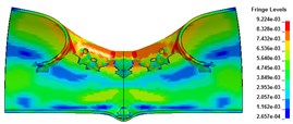
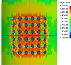
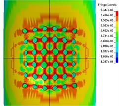
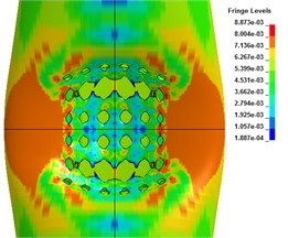
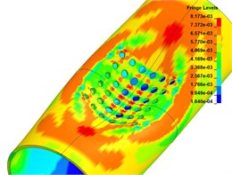
The results show that the steel cylindrical shell with openings has a large stress concentration at the openings subjected to the explosion impact loading, which results in impact damage. Compared with the cylindrical shell without holes, although the area of explosion is reduced, the strength of the cylindrical shell structure has a greater influence on the deformation mode at a smaller stand-off distance due to the whole strength reduction. The shell no longer has large deformation, but has whole displacement. When the stand-off distance is 1 cm, the detonation products and shock waves propagate to the upper surface of the shell, and the whole surface is impacted greatly. When the impact load strength exceeds the ultimate strength of the cylindrical shell with preformed holes, the axial and radial preformed holes in the central area of the shell face form a break-through crack; with the further action of the load, the crack gradually becomes larger until the shell forms a large area gap, which is rectangular in shape. The shell only deforms locally at this time. When the impact time is 300 μs, the whole deformation of the cylindrical shell gradually increases, and shows a relatively obvious whole deformation. The element at the edge of the break loses the constraint at one end, and it deforms violently under the action of shock wave and inertia. Some grid elements roll inward, as shown in Fig. 2 and Fig. 3.
Fig. 2The radial deformation
a) 50 μs
b) 100 μs
c) 300 μs
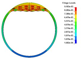
Fig. 3The axial deformation
a) 50 μs

b) 100 μs
c) 300 μs
Fig. 4The displacement-time curve of radial joints
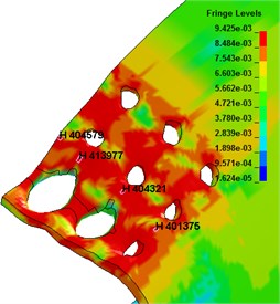
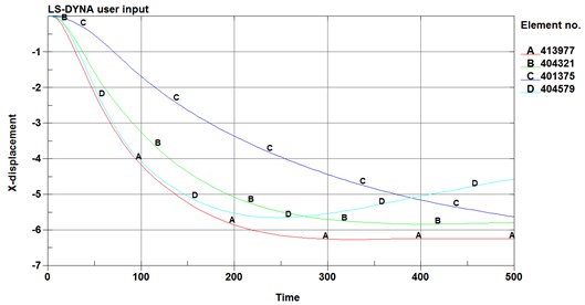
Fig. 5The strain-time curve of the adjacent elements
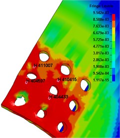
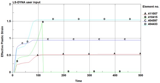
The displacement-time curve of cylindrical shell radial joint is shown in Fig. 4. The displacement of joints subjected to explosion impact loading is in the impacted direction, but some of them tend to move upward in the later stage due to the overturning of the break edge. Fig. 5 is the strain-time curve of the adjacent elements. From the figure, it can be seen that the strain near the second row of holes is much larger than that of the first row of holes, so it is more likely to cause unit failure and structural failure. In which, the failure of element B occurs near 120 μs, and the strain drops to 0. The reason for this phenomenon may be the difference of displacement of different rows of holes under shock wave load, and the pull between grid elements, which leads to serious grid deformation and great stress near the second row of holes, leading to grid failure near the second row of holes.
3.2. 3 cm stand-off distance
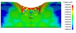
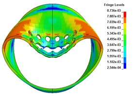
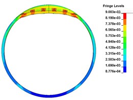
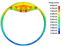
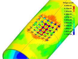
When the stand-off distance is adjusted to 3 cm, the wall of metal tube with preformed hole will produce local deformation of depression subjected to the explosive impact, and the shape of depression area is approximately elliptical. The preformed circular holes at the bottom of the axial plastic hinge of the blasting face are penetrated through, forming two radial through cracks. The crack shape is shuttle shaped, with large middle distance and small distance between the two ends. The thin-walled cylindrical shell only has local deformation, and the whole deformation is not obvious, as shown in Fig. 6 and Fig. 7.
Fig. 6The radial deformation
a) 50 μs
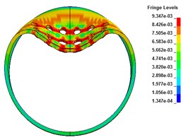
b) 100 μs
c) 300 μs
Fig. 7The axial deformation
a) 50 μs
b) 100 μs
c) 300 μs
3.3. 5 cm stand-off distance
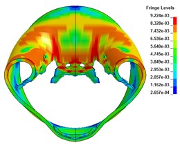
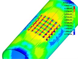
Fig. 8 and Fig. 9 are radial and axial deformations of cylindrical shells with preformed holes. It can be seen from the figure that the cylindrical shell with preformed holes has buckling deformation subjected to explosive impact loading, and there is no through crack on the blasting face, but an elliptical depression pit is formed, and the axial direction of the shell is the long axis and the radial direction is the short axis. Because of the existence of the preformed holes, part of the explosive energy enters the air inside the shell through the preformed holes, resulting in the local and whole deformation amplitude smaller than that of the cylindrical shell without the preformed holes.
The cylindrical shell with preformed holes presents three different deformation modes under three different stand-off distance, namely, local depression deformation, coupling of local depression deformation and global deformation, coupling of global deformation and local penetration. Because of the stress concentration around the preformed holes, when the stand-off distance is 1cm, the cylindrical shells with preformed holes are more likely to produce fragments than those without preformed holes. When the stand-off distance is 3cm, there are two radial cracks in the two plastic hinges of the cylindrical shell with preformed holes, while there is only one radial crack in the center of the blasting face without preformed holes. When the stand-off distance is 5cm, the shell near the preformed hole can resist the blast force. At the same time, the blast energy enters the air inside the shell through the preformed hole, resulting in less blast energy absorbed by the shell, and the size of the sunked nest is smaller.
Fig. 8The radial deformation
a) 50 μs
b) 100 μs
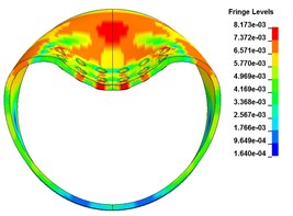
c) 300 μs
Fig. 9The axial deformation
a) 50 μs
b) 100 μs
c) 300 μs
4. Conclusions
1) The ALE coupling model was able to capture the main trend of deformation and perforation failure of the cylindrical shell with preformed holes subjected to explosive impact loading in an adequate manner.
2) The cylindrical shell with preformed holes presents three different deformation modes under three different stand-off distance, namely, local depression deformation, coupling of local depression deformation and global deformation, coupling of global deformation and local penetration.
3) When the shell is subjected to large explosive energy, the cylindrical shells with preformed holes are more likely to produce fragments than those without preformed holes; when the shell is subjected to a small explosive energy, the cylindrical shell with preformed holes has smaller sunken deformation than that without preformed holes.
References
-
He X., Pang W., Qu J., Liu G., Li M. Protective door damaged by air shock wave and fragment arisen from explosion in prototype tunnel. Explosion and Shock Waves, Vol. 5, 2004, p. 475-479.
-
Liu G., Li X. D., Zhang Y. Numerical simulation of combined damage of fragments and shock wave on helicopter rotor. Computer Simulation, Vol. 6, 2013, p. 69-71.
-
Hou H., Zhang C., Li M., Hu N., Zhu X. Damage characteristics of sandwich bulkhead under the impact of shock and high-velocity fragments. Explosion and Shock Waves, Vol. 1, 2015, p. 116-123.
-
Leppänen J. Dynamic Behaviour of Concrete Structures subjected to Blast, Fragment Impacts. Licentiate Thesis, Department of Structural Engineering, Concrete Structures, Göteborg, Chalmers University of Technology, Sweden, 2002.
-
Leppänen J. Experiments and numerical analyses of blast and fragment impacts on concrete. International Journal of Impact Engineering, Vol. 31, Issue 7, 2005, p. 843-860.
About this article

This research was financially supported by the National Nature Science Foundation of China, Nos. 51978660 and 51678567, and the China Postdoctoral Science Foundation No. 2018M633753.
