Abstract
This study presented a reference for design, analysis, and assessment of typical reinforced concrete (RC) piles subjected to a near-field non-contact explosion. In particular, the effects of radius on the dynamic response of the RC piles under such explosion conditions were investigated using the model tests. Furthermore, the damage and safety as well as the failure modes of such piles were analyzed using the numerical simulations. It was demonstrated that such explosions can cause a partial damage for the piles during the stage of shock waves, whereas for the stage of bubble actions, it can lead to a serious damage of the piles. For a certain distance, the failure of the piles was earlier than the bubble pulsation pressure caused at the end of the first pulsation cycle. Compared with the steel bar, the damage of concretes was more serious because the bonds between the steel bar and the concretes became more severe. Based on the experimental and numerical simulation results, a method to assess the damage of such piles under the explosion conditions was proposed, which could be applicable for the anti-explosion design and the safety and fault diagnosis of various industrial facilities and equipment.
Highlights
- This study presented a reference for design, analysis, and assessment of typical reinforced concrete piles subjected to a near-field non-contact explosion
- Effects of radius on the dynamic response were investigated using the model tests
- The damage and safety as well as the failure modes were analyzed using the numerical simulations
1. Introduction
The high-pile facility is one of the important structures and is mainly suitable for foundations with poor soil conditions. During the period of service, besides the normal loads including dead load, live load, seismic load, wind load and water wave load, the high-pile facility may also suffer from the accidental explosive load or terrorist explosive load. Reinforced concrete (RC) pile is one of the popular used vertical load bearing members for high-pile facilities. In this study, typical RC piles were designed and fabricated for an experimental investigation under the near-field non-contact explosion. Numerical modelling of the specimens under the test condition was also established and validated. Based on the experimental data and a series of parametrical modelling analysis, the dynamic response and failure model of the RC pile under the explosion were studied. The method of to assess the damage of the RC pile under near-field non-contact explosion was also studied. In addition, the safety distance of the studied type of RC pile was analyzed under varies explosive load conditions.
Compared with air explosions, explosions are more destructive due to the characteristics of water with greater density and less compressibility. Therefore, the law of shock wave propagation formed by explosive in the two different media, water and air, is quite different. In the water, blast wave travels faster than that in the air, the pressure is greater and the attenuation is slower. Due to the small compressibility and large density of the water, dissipation of explosive energy is much slower in the water than that in the air. Explosion is also characterized by the phenomenon of bubble pulsing. The study of explosion can be traced back to the 1950s. Kuhl [1] summarized the basic phenomenon, mechanism and laws of explosion, and formed a relatively systematic basic theory. The problem of explosion can be divided into three types [2]: far-field non-contact explosion, medium to near-field non-contact explosion and contact explosion. The ratio between the explosion distance and the radius of the explosive cartridge is used as the index () to determine the type of the explosion. If 0 10, it is a contact explosion; If 10 25, it is a near-field non-contact explosion; If 25, it is a far-field non-contact explosion. In different type of explosion conditions, piles of high-pile facilities would perform differently and show different dynamic response and failure mode.
Many scholars have studied the dynamic response and failure mode of RC components or the integrated structure systems under the action of explosion in the air. Shi [3-5] presented the damage analysis and assessment of RC columns under blast impact. Zhu [6, 7] presented analysis and research on the dynamic response and damage process of the multi-layer reinforced concrete frame structure under the impact of explosion. For the explosion situation, studies mainly concentrate on the law of explosion shock wave and the bubble pulsation. In the condition of near-field non-contact explosion, RC structures would suffer the shock wave impact and the bubble pulsation. RC gravity dams were the most popular research subjects which were mainly studied by numerical analysis method. Zhang [8] carried out a full-performance numerical simulation of the dynamic response of the dam under the impact of explosions. Xu [9] established finite element (FE) model to study the dynamic structural response of the concrete gravity dam caused by contact explosion. Lu [10] used FE modelling method to analyze effect of explosion on elastic response and dynamic fracture of the concrete gravity dam. Besides, Yu [11] used numerical modelling method to analyze the dynamic response of RC cylindrical pier subjected to blast wave load, and summarized the internal relationship between the failure mode of circular RC columns and the shock wave. Zhang [12] used finite element modelling method to study the impact of air and explosive shock waves on the dynamic response and damage degree of reinforced concrete slabs. Totally, study of the performance of RC structures subjected to explosion is relatively limit, particularly the RC columns or piles.
In summary, the research on the response and failure modes of hydraulic structures particular the RC structures under near-field non-contact explosion is still in the exploratory stage. Although researches by numerical modelling presented preliminary understanding of the performance of RC structures subjected to explosion, limit experimental data can be used for validation of the modellings and parameters studied in the existing researches cannot cover the conditions in practice. In this study, three typical RC concrete piles were designed and fabricated for the experimental investigation in which the pile specimens were set in water and subjected to nearfield non-contact explosion. The dynamic response and damage process of the specimens in the test were recorded and analyzed. A 3-D numerical model of the RC pile using explicit algorithm was established and validated by the test data. Then, by using the validated modelling method, parametrical analysis was carried out to study effects of near-field non-contact explosion on the dynamic response and failure mode of a certain high-pile RC pile. On the basis of the experimental and modelling investigation, study on damage assessment was carried out and a method to assess the damage of RC piles subjected to the near-field non-contact explosion was proposed. In addition, safety distance of against the studied explosive loading condition was also proposed as a reference for the type of RC piles in practice.
2. Numerical analysis model and model verification
For structural damage research of explosion, experimental research and numerical analysis methods are mostly used at present. In this paper, the failure of reinforced concrete piles of explosion are analyzed by model experimental test and numerical simulation. Numerical analysis model included explosive, water and air. The equation of state and material model is as below.
2.1. Equation of state for explosive, water and air
The explosive is simulated by the JWL equation of state and the expression is as follows[1]:
where is the initial internal energy of unit mass of the explosive; is the relative volume; and are the material parameters; , , and are constants. TNT explosives are used in this study. Values of the parameters are shown in Table 1.
Table 1Parameter values of JWL equation of state of TNT
/ kPa | / kPa | / (g/cm3) | / (m/s) | / (kJ/m3) | / kPa | |||
3.7377e11 | 3.7471e6 | 4.15 | 0.95 | 0.35 | 1.630 | 6930 | 6.0e6 | 2.1e7 |
A polynomial equation of state is used. If the material is stressed in compression, the equation of state is [2]:
If the material is pulled, the equation of state is[6]:
where: , , , , , , are material parameters; ; is the initial internal energy of unit mass. In the literature, it has been mentioned that pure materials can withstand a negative pressure equal or less than one atmosphere, while daily materials containing gaseous impurities can only withstand zero negative pressure. Therefore, the cutoff pressure is uniformly set to zero in the calculation. The specific parameters are shown in Table 2.
Table 2Water equation of state parameter
/ kPa | / kPa | / kPa | / (kg/m3) | / kPa | / kPa | Cutoff pressure / kPa | ||
2.200e6 | 9.540e6 | 1.457e7 | 0.28 | 0.28 | 1000 | 2.200e6 | 0 | 0 |
The material model of air is assumed to be an ideal gas, and the relationship between pressure and energy is:
2.2. Material model
RHT concrete model is a concrete model considering the dynamic characteristics of the material, and the model was adopted for the concrete material in the modelling of this study. The RHT model considers effects of hydrostatic pressure and strain rate, stress strengthening and residual strength of concrete. Effects of damage and crack development on concrete strength are also considered in the RHT model. Based on the default value of conc-35 mPa material model provided by AUTODYN, the parameters were modified and a conc-50 mPa material model was obtained, namely: shear modulus was 17500 MPa, yield strength was 50 MPa, compression strain rate was 0.0287 and tensile strain rate was 0.0326.
To simulate behavior of the steel reinforcement, Johnson-cook model was adopted, which is an ideal elastoplastic constitutive model for metal materials. The Johnson-cook model can reflect the material strengthening caused by strain rate and the softening caused by temperature rise, and the model is suitable for simulating mechanical behavior of steel reinforcement under large strain, large strain rate and high temperature. Parameters of the steel reinforcement were input by using the STEEL 4340 material model provided in AUTODYN material library.
2.3. Model verification
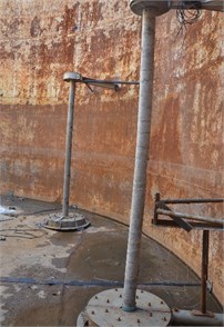
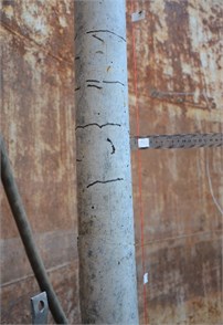
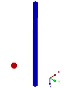
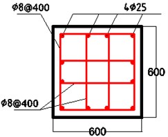
The test of a typical RC pile subjected to near-field non-contact explosion was carried out in a large pool, diameter of which was 10.0 m and the depth was also 10.0 m. The mass of the explosive was 0.4 kg, the depth of the explosive to the surface was 1000 mm and the distance R between the center of the explosive to the surface of the pile specimen was 500 mm. The setting of the test is shown in Fig. 1. The pile specimen is a small-scale circular RC column model with the diameter of 100 mm and the length of 2500 mm. The cross-section and reinforcement of the pile specimen is shown in Fig. 2. Ribbed steel bars were used as the longitudinal steel reinforcement of the pile specimen. The diameter of the longitudinal steel reinforcement was 6 mm and the mean yield strength of that was 335 MPa. The galvanized steel wires of 3mm in diameter were used for stirrup with the spacing of 100 mm. Cube strength of the concrete was 40 MPa, and the concrete was a special concrete material for small-scale structural models and made of fine aggregates. The bottom of the specimen was fixed on the bottom of the pool and the top of it was also fixed through a connecting with the wall of the pool, as shown in Fig. 3. Fig. 4 shows the moment of the explosion.
Fig. 1Overall model setting diagram
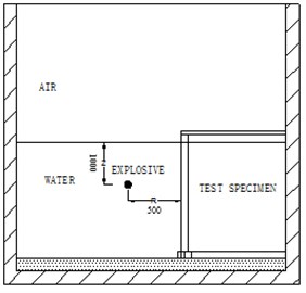
Fig. 2Cross section of the pile specimen
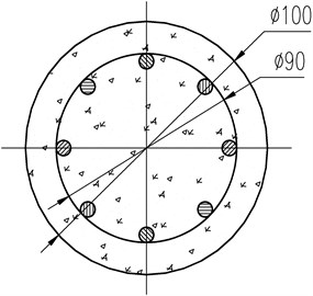
Fig. 3Injection in the test pool
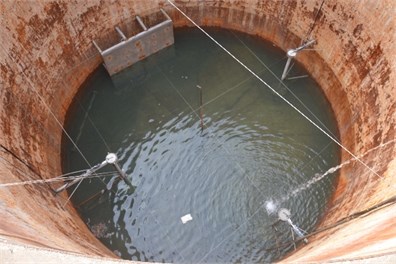
Fig. 4Explosion effect diagram
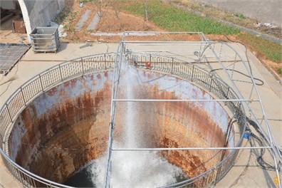
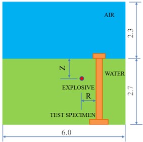
Fig. 5 shows the original state of the RC pile specimen setting in the pool before injection of the explosion test. Deformation of the specimen after the explosion is shown in Fig. 6. As a result of comparison it can be seen that bending deformation of the specimen was caused by the near-field non-contact explosion. The end of the specimen of damaged with concrete cracks. Tiny cracks appeared and distributed in the middle and upper part of the specimen. The cracks were in the circumference direction and uniformly spaced, and the crack space was around 100 mm as the same as the stirrup space. The schematic diagram of the verification model is shown in Fig. 7. The length of the calculation model is 6.0 m, the width is 8.0 m, and the height is 5.0 m. The height of the area is 2.7 m and the height of the air field is 2.3 m. The explosive was TNT of the mass 0.4 kg.
Fig. 5Shape of the specimen before the explosion
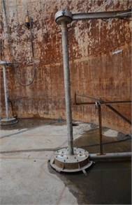
Fig. 6Deformation of the specimen after the explosion
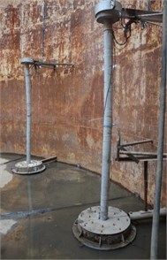
Fig. 7Validation model schematic diagram
a) Schematic plan view
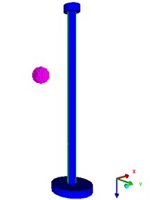
b) Three-dimensional schematic
Fig. 8Test result diagram
a) Overall damage result
b) Residual displacement result
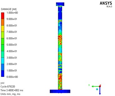
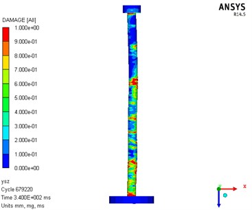
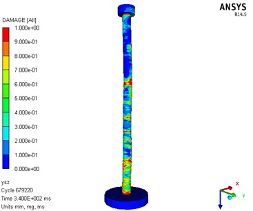
Figs. 8-10 show a comparative analysis diagram of the numerical analysis and test results. The RC pile was shown failure in bending. The numerical calculation and test results show that the damage at the back surface of the RC pile was more serious than that at the impact surface. The end of the test piece is also damaged.
Fig. 9Displacement contrast diagram
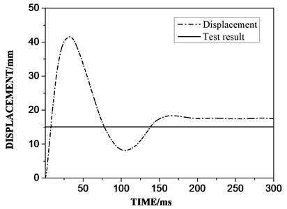
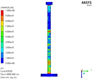
Fig. 10Numerical analysis result diagram of damage
a) Explosive surface
b) Back explosion surface
c) Side façade
d) Three-dimensional schematic
From the final residual deformation of the components, the difference between the numerical simulation (17.5 mm) and the test results (15.1 mm) is about 15 %, which is within the allowable range of the project. From the final residual deformation of the component, the numerical simulation (17.5 mm) and the test result (15.1 mm) are about 15 %, which is within the allowable range of the project; After the test, the pile specimen was in a state of failure with small residual bearing capacity; For the global damage phenomenon, bending deformation of the RC pile was shown by both the numerical analysis and the test. The position of the maximum residual deformation was almost the same in the modelling and test. For the local damage, concrete damage occurred in the middle section and both ends of the pile. However, damage of the upper section of the pile was relatively insignificant compared with that of the other parts. The numerical modelling results were close to the experimental results.
The numerical analysis model of this paper can be used to analyze the dynamic response and failure mode of reinforced concrete piles under near-field blast loading.
3. Study on performance of RC piles subjected to near-field non-contact explosion
3.1. Numerical analysis model
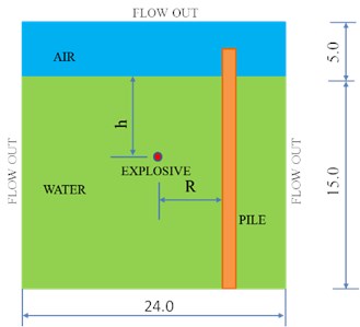
According to an actual high-pile facility project, a calculation model for the failure effect of RC piles under near-field non-contact explosion was established. As shown in Fig. 11, the length of the model is 24.0 m, the width is 24.0 m, and the height is 20.0 m. Height of the area is 15.0 m and that of the air area is 5.0 m. The number of grids in the computational domain was 2.94 million. The TNT quality was chosen to be 60 kg.
Cross-section of the designed RC pile model was square and the wide was 0.6 m. The height of the pile was 18.0 m. As shown in Fig. 12, there are 12 longitudinal steel bars of 25 mm in diameter, and the stirrups are 8 mm in diameter and the stirrup spacing is 400 mm. Concrete is calculated by Lagrange solver, steel is calculated by beam solver, water and air are calculated by Euler solver.
Fig. 11Sketch map of 3D model
a) Schematic plan view (m)
b) Three-dimensional schematic
Fig. 12Reinforcement diagram of reinforced concrete pile section
The explosion shock wave and bubble simulation adopt the mapping setting to import the one-dimensional calculation result into the three-dimensional model, which improves the calculation precision and saves the calculation time and computer resources. Joint is used to connect the steel bar and concrete, and the bottom end of reinforced concrete piles adopts consolidation boundary conditions. The top of the RC piles was applied with uniform load, the axial compression ratio is 0.2; the air and boundaries are the flow out boundaries. In this study, different position of the explosive was considered to investigate the influence of the explosion on the behavior of the RC pile. As variables, depth of the explosive was 2.0 m, 8.0 m and 14.5 m respectively, and the explosion distance was 2.5 m, 3.5 m and 5.0 m respectively. The selection of explosion distance here is related to the number of radius, which is the ratio of explosion distance to charging radius.
3.2. Analysis of failure mode of reinforced concrete piles
3.2.1. Analysis of typical load conditions
DAMAGE is used as an indicator to measure structural damage. The closer the magnitude is to 1, the greater the damage; the magnitude 1 indicates complete destruction of the structure. The objects analyzed in this section are the load condition four (explosion depth 8.0 m, explosion distance 2.5 m) and working condition six (explosion depth 8.0 m, explosion distance 5.0 m). The detailed load and response process of the modelling under two of the load conditions (load condition four and load condition six) was presented below as examples.
Fig. 13 shows the damage evolution process of the RC pile under the fourth load condition, and the shown graphs are at the time of 3 ms, 15 ms, 30 ms, 45 ms, 60 ms, respectively. In the stage of shock wave, the damage of the RC pile was insignificant. With the development of the explosion, bending deformation and damage of the RC pile gradually increases. Damage of the back surface of the pile was found severer than that of the impact surface, and the concrete damage distributed in a large area. Damage at the impact surface mainly concentrated on the bottom and body of the RC pile within a certain range of the explosion source; while damage at the back surface mainly concentrated in the pile body. Finally, the body of the RC pile broke and the bottom of the pile also damaged.
Fig. 13Damage evolution diagram of reinforced concrete pile under working condition four
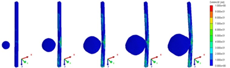
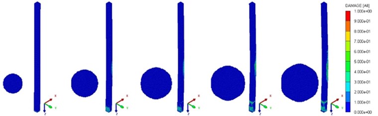
Fig. 14 shows the damage evolution process of the RC pile under the load condition six, and the shown graphs are at the time of 9 ms, 24 ms, 36 ms, 48 ms, 66 ms, respectively. It can be seen from the damage evolution process that in the early stage of the blasting load, damage of the RC pile was insignificant. Under the action of the explosion, the water exerted an impact force on the pile and caused deformation in bending. When the development of the bubble pulsation was sufficient, the impact of the water on the pile become severer and resulted in a large displacement in the middle section of the pile. The damage of the RC pile was shown significant particularly shown at the bottom of the pile and the back surface. In the end, the concrete damaged, and the RC pile was shown damaged in shearing.
Table 3 shows the damage analyses of the load conditions 1, 2 and 4, Table 4 shows those of the load conditions 6, 7 and 9, and Table 5 shows those of the load conditions 11, 12 and 14. From the result analysis, it can be seen that the RC pile damage effect is affected by the explosion shocking wave. The effect is small, but it is greatly affected by the bubble pulsation process.
Fig. 14Damage evolution diagram of reinforced concrete pile under working condition six
Based on above analyses and comparison of the dynamic response and damage process of the RC pile under the action of the near-field non-contact explosions, the following conclusions can be drawn: the RC pile is in a certain range of explosion distance, and the pile is mainly in local failure. With the increase of blasting distance, shear failure, shear failure and bending failure occurred successively in reinforced concrete piles. As the blasting distance increases, the concrete damage gradually decreases. The damage of concrete increases with the increase of blasting depth. As the depth of explosion increases, the failure of pile bottom will increase.
Table 3Failure analysis of the RC pile in the load conditions 1, 2 and 3
The load condition 1 | The load condition 2 | The load condition 4 | |
Final damage and morphology of reinforced concrete piles | 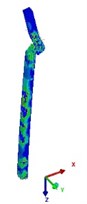 138 ms | 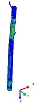 138 ms | 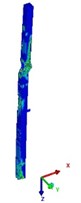 144 ms |
Failure analysis | Severe punching and shearing; serious damage at the bottom of the pile; damage at other parts of the pile to some extent | Severe punching and shearing; serious damage to the bottom of the pile | Bending shear failure; damage to other parts of the pile to some extent |
Table 4Failure analysis of the RC pile in the load conditions 6, 7 and 9
The load condition 6 | The load condition 7 | The load condition 9 | |
Final damage and morphology of reinforced concrete piles | 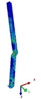 162 ms | 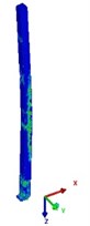 156 ms | 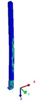 177 ms |
Failure analysis | Severe punching and shearing; Severe shear failure at the bottom of the pile; serious damage to the concrete on the back of the pile | Bending shear damage; Pile back explosion surface concrete damage is serious; Serious shear failure at the bottom of the pile | Bending and shearing failure; concrete damage on the back of the pile back; general shear failure of the pile bottom |
Table 5Failure analysis of 14.5 m reinforced concrete pile with depth of explosion
The working condition 11 | The working condition 12 | The working condition 14 | |
Final damage and morphology of reinforced concrete piles | 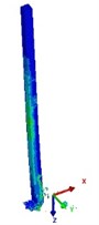 150 ms | 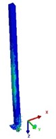 150 ms | 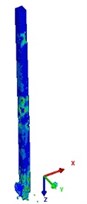 276 ms |
Failure analysis | Severe punching and shearing at the pile bottom | Severe punching and shearing at the pile bottom | Bending failure; large area concrete damage at the bottom of the pile |
3.3. Damage assessment of the RC pile
3.3.1. Structural damage assessment method
According to previous research results [3], the residual bearing capacity was adopted in this study to evaluate the damage level of the RC pile under blast loading. The damage index is defined as:
where is the residual axial bearing capacity of the RC pile with damage caused by the explosion; is the axial ultimate bearing capacity of the RC pile without damage caused by the explosion According to the value, the damage of RC piles can be classified to four levels, as shown in Table 6.
Table 6Classification of structural damage
The damage level | |
0-0.2 | Slightly damaged |
0.2-0.5 | Moderate damage |
0.5-0.8 | Severe damage |
0.8-1.0 | Serious collapse |
The axial ultimate bearing capacity of the RC pile without explosive damage and the residual vertical bearing capacity with various level of explosive damage were obtained by using the numerical modelling. For the pile without explosive damage, the vertical bearing capacity of the RC pile was calculated based on the same numerical model for the explosion analysis. The axial compression was applied on the top of the pile until failure. The velocity load was applied slowly.
The residual axial bearing capacity of the RC pile with explosive damage was relatively complicated, which can be obtained following the steps below:
(1) Establish a finite element model of the RC pile and apply axial pressure on the top of the pile. The axial load value equaled to 10 % of the axial ultimate bearing capacity of the pile without explosive damage. The axial compressive pre-load kept constant during the period of the following explosive loading.
(2) Simulate the near-field non-contact explosion on the RC pile. As measurement of the residual vertical bearing capacity of the RC pile after the explosion should be carried out when the pile structure reaches a state of relative static balance. Referring to the method for evaluating the damage of structures subjected to explosion in the air [3-5], the simulation calculation should be stopped when the joint speed of RC pile is lower than 0.1 m/s.
(3) Measure the remaining vertical bearing capacity of the pile on the basis of the damaged model without the water and explosion conditions. The displacement load is slowly applied to the top of the RC pile until the RC pile is damaged.
3.3.2. Damage evaluation of the reinforced concrete pile
Since the above presented modellings resulted in ignorable residual bearing capacity, five more load conditions were selected again for analysis. The specific load conditions are shown in Table 8. For all the modellings based on the verified modelling method, the charge amount of the explosive is 60 kg and the depth of the explosive is 8.0 m. The explosion distance is considered as a variable and the effect of which was investigated. The evaluation results are shown in Table 7. It can be seen that with the increase of the explosion distance, the RC pile mainly suffers from bending failure, and the degree of damage gradually decreases.
Table 7Damage assessment form of the reinforced concrete pile
The load condition | Explosion depth / m | Explosion distance / m | Ultimate bearing capacity / kN | Residual bearing capacity / kN | Damage parameter | The degree of damage |
The working condition 1 | 8.0 | 8.0 | 2028.6 | 393.264 | 0.8061 | Severe collapse |
The working condition 2 | 9.0 | 2028.6 | 787.104 | 0.6120 | Severe injury | |
The working condition 3 | 10.0 | 2028.6 | 1291.284 | 0.3635 | Moderate injury | |
The working condition 4 | 12.0 | 2028.6 | 1724.004 | 0.1502 | Slight injury | |
The working condition 5 | 15.0 | 2028.6 | 1865.592 | 0.0804 | Slight injury |
3.4. Study on safety distance of the reinforced concrete pile under near-field explosion
Under the circumstance of near-field non-contact explosion, factors to affect the damage pattern of the RC pile are various. Under different conditions of the explosion, effects of the explosion on the dynamic response and damage of the RC pile are different, such that the safety distance changes with the explosion conditions accordingly. With the help of the above finite element model, the effects of charge quality, explosion depth, hooping ratio and concrete strength parameters on the damaging and safety distance of the RC piles under the near-field non-contact explosion are further studied.
3.4.1. Effect of explosive quality
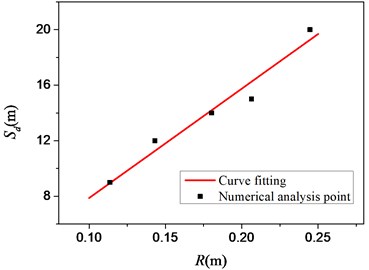
Explosive quality is related to the input of the explosion energy for the modellings, and it also affects the structural damage. Assuming the explosion depth was 8.0 m, the axial compression ratio was 0.1, and the explosive quantity was 10.0 kg, 20.0 kg, 40.0 kg, and 100.0 kg, respectively, and the charging method is still a spherical charge, and the others are the same as the aforementioned model. The safety distance and damage degree of the RC pile under the explosion with different explosive doses are shown in Table 8. It shows the recent explosion distance of reinforced concrete piles with less than 10 % damage under different doses.
The fitting relation between the charging radius and the safe distance calculated according to different loading quantities is shown in Fig. 15. The abscissa is the charging radius (the explosive mass is related to the charging radius, and the radius number is the ratio between the blasting distance and the loading radius), and the ordinate is the safety distance. According to the above results, the relation between charge radius () and safe distance () can be obtained, namely:
where the unit of is meter; is the safety factor only related to the explosive quality, and the value of the factor is weighted to be 78.75; the unit of is meter.
Table 8Safety distance and damage of different charge quality
Explosive quality / kg | Explosive distance / m | Radius number | Damage parameter | The degree of damage |
10.0 | 9.0 | 79.2504 | 7.10 % | Slight injury |
20.0 | 12.0 | 83.8681 | 4.56 % | Slight injury |
40.0 | 14.0 | 77.6605 | 6.78 % | Slight injury |
100.0 | 20.0 | 81.7439 | 5.40 % | Slight injury |
Fig. 15Relationship between safety distance and explosive radius
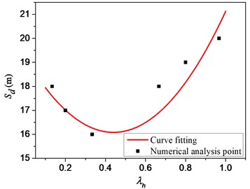
3.4.2. Effect of explosion depth
Depth of the explosion mainly affects the impact position of the RC pile subjected to the explosion, and also results in different reflective phenomenon of the surface and the bottom of the water. Damage of the RC pile subjected to the explosion would be affected by the explosion depth. Considering the explosive quality was set as 60.0 kg, the explosion depth was set to 3.0 m, 5.0 m, 10.0 m and 12.0 m, respectively. Table 9 shows the safety distance and damage of the RC pile under different explosion depths.
Table 9Safety distance and damage of the RC pile with different depth of explosion
Explosion depth / m | Explosion distance /m | Depth ratio | Damage parameter | Degree of damage |
3.0 | 17.0 | 0.20 | 6.40 % | Slight injury |
5.0 | 16.0 | 0.33 | 8.62 % | Slight injury |
10.0 | 18.0 | 0.67 | 4.78 % | Slight injury |
12.0 | 19.0 | 0.80 | 4.80 % | Slight injury |
The depth of explosion has a significant impact on the damage of the RC pile in the near-field non-contact explosion. () is defined as normalized depth or depth coefficient, where is the depth of the charge with the unit in m, and is the calculated depth in m. The fitted curve is shown in Fig. 16. Combined with the previous research results, the comprehensive consideration of the charge amount and the explosion depth can be obtained. The formula, is:
where is the safety distance with the unit in m; is a safety factor considering the charge quality and the charge depth and the coefficient is calculated to be 78.07; is the normalized depth coefficient. is the charge radius in m.
Fig. 16Relationship between safety distance and depth coefficient of the explosion
3.4.3. Influence of steel hoop ratio
The hoop ratio is an important parameter related to strength of reinforced concrete structural members. Increase of the hoop ratio can enhance the bearing capacity, integrity and ductility of the RC structural members, and also change the deformation performance. Considering the circumstance of the explosion, increase of the hoop ratio can reduce the damage degree of the RC structural members or reduce the safety distance to a given explosion condition.
In order to understand the influence of the hoop ratio on the RC pile and determine the corresponding safety distance, the spacing of the hoops is set to 100 mm, 150 mm, 200 mm, 250 mm and 300 mm respectively. The explosion depth was set as 8.0 m for all the modellings in this section. The rest of the settings are the same as the previous part. The safety distance and damage of the RC piles with different hoop ratios are shown in Table 10.
Table 10Safety distance and damage of different stirrup rates
Stirrup spacing / mm | Explosion distance / m | Clamping ratio | Damage parameter | Degree of damage |
100 | 11.0 | 0.3353 % | 4.58 % | Slight injury |
150 | 12.0 | 0.2236 % | 6.14 % | Slight injury |
200 | 13.0 | 0.1677 % | 5.86 % | Slight injury |
250 | 14.0 | 0.1341 % | 5.40 % | Slight injury |
300 | 14.0 | 0.1118 % | 6.80 % | Slight injury |
Fig. 17Relationship between safety distance and hoop ratio
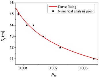
The fitted relationship between the different hoop ratios and the safety distance of the RC pile is shown in Fig. 17. Combined with the previous research results, the comprehensive consideration of the charge, explosion depth and hoop can be obtained. The fitted formula for the rate, namely:
where is the anti-explosion safety distance, the unit is meter; is the safety factor considering the charge quality, burst depth and the hoop ratio. This coefficient is calculated to be 14.50 after fitting calculation. is the hoop ratio, , is the cross-sectional area of the stirrup, is the width of the member, which is perpendicular to the shear direction, is the hoop spacing, and is the coefficient. The value is –0.228; is the normalized depth coefficient; is the charge radius in meter.
3.4.4. Influence of concrete strength
Concrete strength mainly affects the bearing capacity and stiffness of RC structures. Increasing the strength of concrete can reduce the damage degree of explosion to the structure, thus improving the safety performance of the structure.
In order to understand the influence of concrete strength on the RC pile under the near-field non-contact explosion, the concrete strength grades were set to 35 MPa, 60 MPa, 80 MPa, 100 MPa, 120 MPa and 140 MPa, and the explosion depth was set as 8.0m for all the modelling in this section. The rest of the settings were the same as before. The safety distance and the damage of the RC pile of different concrete strength subjected to the explosion are shown in Table 11.
Table 11Safety distance and damage of different concrete strength grades
Concrete grade | Explosion distance / m | Level coefficient | Damage parameter | Degree of damage |
35 MPa | 17.0 | 0.35 | 12.16 % | Slight injury |
60 MPa | 16.0 | 0.60 | 6.83 % | Slight injury |
80 MPa | 13.0 | 0.80 | 0.83 % | Slight injury |
100 MPa | 11.0 | 1.00 | 4.76 % | Slight injury |
120 MPa | 11.0 | 1.20 | 3.37 % | Slight injury |
140 MPa | 10.0 | 1.40 | 9.26 % | Slight injury |
Fig. 18Relationship between safety distance and strength coefficient of concrete
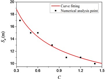
The fitting relationship between the concrete strength and the safety distance of the RC pile under the explosion is shown in Fig. 18. Based on Eq. (8), a fitting formula that comprehensively considers the charge amount, explosion depth, hoop ratio and concrete strength grade can be obtained, namely:
where is the anti-explosion safety distance, the unit is meter. is the safety factor considering the charge quality, burst depth, concrete strength grade and hooping ratio, and this coefficient is calculated to be 11.25. is concrete. The strength grade coefficient is defined as 0.01 times the concrete strength grade value, is the concrete strength grade coefficient index, and the value is –0.392; is the hoop ratio, and is the coefficient, the value is –0.228; is normalized Depth factor; is the charge radius in meter.
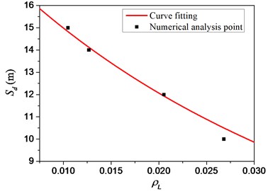
3.4.5. Effect of longitudinal steel bars ratio
The longitudinal steel bars ratio of reinforced concrete structures has a significant impact on the damage and damage of reinforced concrete piles under near-field blast loading. Increasing the longitudinal steel bars ratio will increase the structural integrity and improve the safety performance of the structure. In order to understand the effect of the longitudinal steel bars ratio on the damage and damage of the near-field explosion reinforced concrete pile, the longitudinal steel bars diameter is set to 20 mm, 22 mm, 28 mm and 32 mm, and the explosion depth is 8.0 m, as shown in Table 12. The rest are the same as the previous part.
Table 12Safety distance and damage of different reinforcement ratio
Longitudinal steel bars diameter / mm | Explosion distance / m | Reinforcement ratio | Damage parameter | Degree of damage |
20 | 15 | 1.05 % | 15.42 % | Slight injury |
22 | 14 | 1.27 % | 8.89 % | Slight injury |
28 | 12 | 2.05 % | 14.69 % | Slight injury |
32 | 10 | 2.68 % | 11.18 % | Slight injury |
In the near-field blasting load, the fitting relationship between the longitudinal steel bars ratio of the pile and its explosion safety distance is shown in Fig. 19. Combined with the previous calculation results, a fitting formula that comprehensively considers the charge amount, explosion depth, hoop ratio, concrete strength grade, and longitudinal steel bars ratio can be obtained, namely:
where is the anti-explosion safety distance, the unit is meter. is the safety factor considering the charge quality, burst depth, hooping ratio, concrete strength grade and longitudinal reinforcement ratio, and the coefficient is calculated to be 15.50 after fitting calculation. is the longitudinal reinforcement ratio, , is the reinforcement area, is the area of the cross section of the test piece, and is the coefficient, the value is –2.725. is the concrete strength grade coefficient, is concrete of strength grade coefficient index, which is –0.392. is the hoop ratio, and is the coefficient, the value is –0.228. is the normalized depth coefficient. is the charge radius, and the unit is meter.
Fig. 19Relationship between safety distance and reinforcement ratio
4. Conclusions
In this study, a typical RC pile was designed and fabricated for experimental investigations under a near-field non-contact explosion. The failure mode of the RC pile specimen was observed and recorded using the model tests, and damage analysis and assessment were carried out. The test results were also supported and verified using the numerical simulations. A detailed 3-D numerical model was established to analyze the RC pile specimens under the explosive loads, and the numerical simulations were consistent with the experimental tests. It was found that such explosions can cause a partial damage for the piles during the stage of shock waves, whereas for the stage of bubble actions, it can lead to a serious damage of the piles. For a certain distance, the failure of the piles was earlier than the bubble pulsation pressure caused at the end of the first pulsation cycle. Compared with the steel bar, the damage of concretes was more serious because the bonds between the steel bar and the concretes became more severe. Based on the experimental and numerical simulation results, a method to assess the damage of such piles under the explosion conditions was proposed, which could be applicable for the anti-explosion design and the safety and fault diagnosis of various industrial facilities and equipment.
References
-
Cole R. H. Explosion. Princeton University Press, New Jersey, 1948.
-
Cui Jie Experimental Study on Explosion Bubble Loads and Damage on the Structure. Harbin Engineering University, 2013.
-
Shi Yan-Chao Dynamic Response and Damage Mechanism of Reinforced Concrete Structures under Blast Loading. Tianjin University, 2009.
-
Yan Qiu-Shi, Du Xiu-Li Damage evaluation for a column of a typical subway station subjected to internal blast loading. Journal of Vibration and Shock, Vol. 36, Issue 1, 2017, p. 1-7.
-
Conrad K., Abass B. Effects of transverse reinforcement spacing on the response of reinforced concrete columns subjected to blast loading. Engineering Structures, Vol. 142, 2017, p. 148-164.
-
Zhu Sheng-Bo Investigation on Anti-Explosion Performance of Reinforced Concrete Structure under the Close-In Explosion. Zhejiang University, 2010.
-
Zheng Jian Damage Analysis of Reinforced Concrete Frame Structure under Blast Loading. Hunan University, 2012.
-
Zhang She-Rong, Wang Gao-Hui Antiknock performance of high arch dam subjected to shallow water explosion. Journal of Tianjin University, Vol. 46, Issue 4, 2013, p. 315-321.
-
Xu Qiang, Cao Yang, Chen Jian-Yun, et al. Study on the response and damage characteristic of concrete gravity dam subjected to contact explosion. Journal of Hunan University, Vol. 43, Issue 7, 2016, p. 62-74.
-
Lu L., Li X., Zhou J., et al. Numerical simulation of shock response and dynamic fracture of a concrete dam subjected to impact load. Earth Sciences Research Journal, Vol. 20, Issue 1, 2016, p. 1-5.
-
Yu Jian-Hua Research on Action Effect and Protection for pier subjected to explosion loads. Wuhan University of Technology, 2014.
-
Kong Xiang-Qing, Zhao Qian, Qu Yan-Dong, et al. Dynamic responses of a concrete slab subjected to air and explosions. Science and Technology Review, Vol. 34, Issue 18, 2016, p. 279-286.
-
Liu Ke-Zhong, Xu Geng-Guang, Xin Chun-Liang, et al. Research on numerical simulation in explosion by Autodyn. Blasting, Vol. 26, Issue 3, 2009, p. 18-21.
-
Lou Hao-Ran, Hu Jing, Liang Xiang-Qian, et al. Explosion experiment and numerical simulation of spherical explosives under hypergravity field. Engineering Blasting, Vol. 23, Issue 3, 2017, p. 15-21.
About this article

Mingxin Bai has made a substantial contribution to all the experimental observations and investigation. Xianglian Xu has made a substantial contribution to design to the concept or design of the article. Hongxing Yang has made a substantial contribution to the acquisition and analysis of the article. Meng Xiong has made a substantial contribution to the interpretation of data for the article. Wenqiang Zhu has drafted the article and revised it critically for important intellectual content. Zhaopeng Liu has approved the final version to be published. Chenhu Luo has made a substantial contribution to the experimental measurements and analysis of the results.
