Abstract
The structural response of a cylindrical shell with pre-formed holes subjected to explosive impact loading can be efficiently modeled using the ALE coupling model. The damage process and measurement of point deflection were analyzed based on the results of simulation. Results demonstrated that the pre-formed holes on cylindrical shells will destroy their structural strength. This finding will easily lead to stress concentration, which may affect the damage process and decrease the anti-blast ability of cylindrical shells subjected to explosive impact loading. The pre-formed holes can reduce the load area and weaken the effect of impact loading. Change in hole spacing will influence these factors and affect the deformation of cylindrical shell. The location of the break is different when the distance between the holes is different.
Highlights
- The structural response of a cylindrical shell with pre-formed holes can be efficiently modeled using the ALE coupling model.
- With the increase of the preformed-hole numbers, the larger the area of sunken deformation of the blasting face of the cylindrical shell is, the longer the plastic deformation time is.
- The distance between preformed holes has a great influence on the anti-explosion ability of cylindrical shell structure.
1. Introduction
As a typical component of the main structure of the aircraft such as missile and rocket, metal tube is widely used in the field of aviation and aerospace. At present, the damage to missile targets mainly depends on two damage elements, fragments and shock waves, which are produced after the explosion of interceptor warhead. Because of the complex mechanism and many influencing factors, it is difficult to study the combined effects of fragments and shock waves. Therefore, the research on the damage effect of thin-walled cylindrical shell structure under the combined action of fragments and blasting wave has a strong practical application value, and is a hot research issue in the field of anti-explosion protection.
Hoo Fatt [1] and Wierzbicki [2] carried out theoretical research on damage assessment of semi-infinite thin shell subjected to lateral impact loading. Gurney [3] put forward the most widely used Gurney formula in calculating the initial velocity, considering the explosive mass, shell mass and shell parameters, which can give the approximate value of the initial velocity of fragments. Curran [4] carried out the research on the fragment size and distribution formula of explosive fragment. Jin Qiankun [5] uses dynamic explicit nonlinear finite element software to simulate the damage effect of cylindrical shell under the combined action of fragments and shock wave, and verifies the rationality of the material model and parameter selection of cylindrical shell. Leppanen [6] studies the fragments and shock wave time to reach the structure surface when the conventional ammunition (including 50 % TNT charge) with a weight of 250 kg exploded. The results show that when the distance from the center point of ammunition explosion is 5 m, the fragments and shock wave act on the structure surface almost at the same time. When the distance is less than 5 m, the shock wave of explosion will arrive at the structure surface before the fragments. When the distance is more than 5 m, the fragments will act on the structure surface before the shock wave.
According to the above research, after the explosion of conventional weapons, fragments mainly rely on high-speed impact, penetration and other damage to the strength and integrity of the structure, resulting in damage. Shock wave mainly causes deformation and damage to the structure through high-speed impact. When the shock wave acts on the target structure earlier than the fragment, for the structure body, it first produces buckling, deformation and then is impacted and penetrated, which can be regarded as the superposition of the shock wave and fragment alone; the probability of the shock wave and fragment reaching the structure surface at the same time is very small. The coupling of shock wave and fragment can only be reflected by the damage mode of first being impacted, penetrated and then impacted by shock wave. In this paper, the preformed round holes are used to simulate the impact penetration effect of the structure surface, the numerical simulation of the cylindrical shell with preformed holes subjected to the explosive impact loading is carried out, the deformation failure mode of the cylindrical shell is observed and recorded, and the influence of the size characteristics of the preformed holes on the cylindrical shell deformation is discussed, which lays a solid foundation for the development of anti-explosion protection.
2. Calculation model
The numerical simulations of the preformed hole cylindrical shell subjected to explosion impact loading are performed with the commercial finite element code LS-DYNA applying the Arbitrary Lagrangian Eulerian (ALE) technique for the fluid. The ALE model of the cylindrical shell involves three different material types. The first material model represents metallic cylindrical shell, followed by the TNT cylindrical explosion charge, and finally the surrounding air media, which is used to fill the space affected by the explosion charge. Note that in the purely Lagrangian approach, only one type of material model is needed, namely for the metallic cylindrical shell. The mesh size of the air and TNT charge is 0.25 cm. The shell grid size adjacent to the preformed hole is 0.125 cm, and the rest is 0.5 cm. By using the inherent symmetry of the studied problem, calculation time can be saved. Thus, only a quarter of the cylindrical shell was modeled with the appropriate boundary conditions applied along the symmetry planes. The model shows 75 g TNT explosion impact loading constructed with SOLID164 solid element and g-cm-μs unit.
3. Results and analysis
3.1. The influence of the number of holes on the damage effect of metal cylindrical shell structure
A 1/4 model of 25cm short steel pipe is established. The shell material is Q235 steel, the outer diameter is 10 cm, the wall thickness of cylindrical shell is 2.75 mm, the hole diameter of the preformed hole on the shell surface is 6 mm, the hole distance is 6mm (the distance from the hole edge to the hole edge), and the stand-off distance is 5 cm. For the same cylindrical shell, the blasting area is affected by the number of holes, which will affect the structural strength of the blasting surface. Therefore, the influence of the number of holes on the deformation mode is the comprehensive result of the coupling of the blasting area and structural strength. In this paper, 2×2, 3×3, 4×3 openings are used for numerical simulation.
The plastic deformation occurs on the blasting surface of cylindrical shell subjected to explosive impact loading, forming an elliptical depression, without through crack and impact damage. At 300 μs, the displacement of the center point of the blasting face of the cylindrical shell reaches the maximum, which is 3.4 cm. After 300 μs, because of the whole structural strength and the toughness of the steel material, the elastic vibration (vibration amplitude is 2-3 mm) occurs in the bottom area of the sunken nest.
Fig. 3 shows the displacement-time curve of axial elements. It can be seen from the figure that the closer to the center point of the blasting surface, the greater the displacement. At 50 μs, the strain of each unit increases rapidly, and then the strain of the unit far away from the explosion center increases gradually, with a maximum of 0.08, as shown in Fig. 4. Because there are few preformed holes, the deformation of the shell with preformed holes is almost the same as that of the shell without preformed holes. The element far away from the center of the blasting face is located at the edge of the sunken nest, so it will produce more effective strain than other elements.
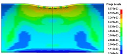
Fig. 1The radial deformation (R= 5 cm, 6 holes)
a) 50 μs
b) 100 μs
c) 300 μs
Fig. 2The axial deformation (R= 5 cm, 6 holes)
a) 50 μs
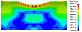
b) 100 μs
c) 300 μs
Fig. 3The displacement-time curve of axial elements

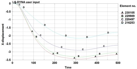
Fig. 4The strain-time curve of the axial elements
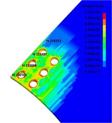
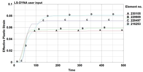
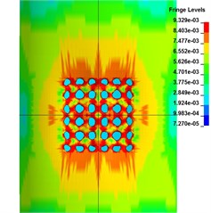
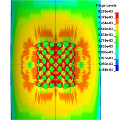
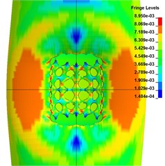
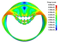
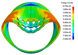
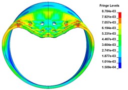
Fig. 3 shows the radial deformation of cylindrical shell with 6 holes, 9 holes, 12 holes. It can be seen from the figure that with the increase of the preformed-hole numbers, the larger the area of sunken deformation of the blasting face of the cylindrical shell is, the longer the plastic deformation time is. Under the condition of 12 holes, because the number of holes affects the structural strength of the blasting surface, the elliptical minor axis of the surface depression is the largest, the cross section is compressed more “flat”, and the deformation time is longer. Under the condition of 6 holes, the anti-explosion ability of the cylindrical shell structure has little change, and because of the existence of preformed holes, the detonation products acting on the shell enter the air inside the cylindrical shell through the preformed holes, reducing the pressure acting on the cylindrical shell, resulting in a relatively small displacement of the center point of the blasting surface. Under the condition of 9 holes, the displacement of the center point of the blasting face is 3.63 cm at 300 μs, and the sunken nest is more flat, which shows that the strength of the cylindrical shell structure is further weakened.
Fig. 5The radial deformation (T= 300 μs)
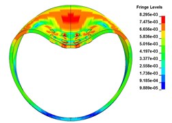
a) 6 holes
b) 9 holes
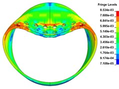
c) 12 holes
3.2. The influence of the distance between preformed holes on the damage effect of metal cylindrical shell structure
A 1/4 model of 25 cm steel pipe is established. The shell material is Q235 steel, the outer diameter is 10 cm, the wall thickness of the cylindrical shell is 2.75 mm, the diameter of the preformed hole on the shell is 6 mm, 3 rows of 9 holes are opened on the blasting face of the shell, and the stand-off distance is 3 cm, hole distance is 2 mm, 6 mm, 10 mm. Under the same explosion conditions, the opening density is adjusted by changing the hole distance, so as to affect the structural strength of the cylindrical shell, and to explore the influence of different hole distance on the damage effect.
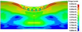
Fig. 6The radial deformation (D= 2 mm)
a) 50 μs
b) 100 μs
c) 300 μs
Fig. 7The top view of deformation of blasting face (D= 2 mm)
a) 50 μs
b) 100 μs
c) 300 μs
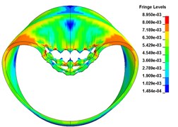
Fig. 7 is the top view of the deformation of the blasting face. It can be seen from the figure that the distance between the preformed holes is relatively close, which has a great impact on the strength of the cylindrical shell. Because of the existence of preformed holes, it is easy to produce stress concentration around them. The blasting face of cylindrical shell has a large plastic deformation, and the hole area has a downward depression, and the grid failure occurs at the axial edge of the sunken nest.
Fig. 8 is the displacement-time curve of radial elements. It can be seen from the figure that the displacement of radial preformed hole decreases obviously from the middle to both sides, and there is no sudden change of displacement greater than 1cm on both sides of the hole. Because the cross section is circular, the arc of the opening part is about 30 degrees, which is more stable than the straight axial structure, so there is no grid damage.
Fig. 8The displacement-time curve of radial elements
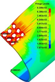
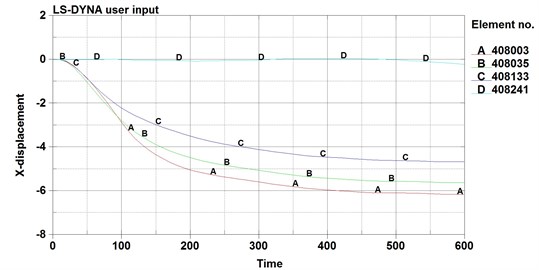
Fig. 9The radial deformation (T= 300 μs)
a)
b)
c)
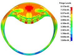
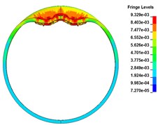
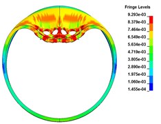
Fig. 9 shows the radial deformation of cylindrical shells subjected to explosive impact loading with hole spacing of 2 mm, 6 mm and 10 mm. From the results of numerical simulation, the distance between preformed holes has a great influence on the anti-explosion ability of cylindrical shell structure. When the opening density is large, the blasting surface of the cylindrical shell is quickly crushed by the impact load, and the stress concentration near the preformed hole is obvious, and the structural strength is reduced. When the hole distance is 6 mm, the explosion impact load also causes the cylindrical shell to form a sunken nest on the blasting face, and produces a crack, and the structure does not have a large whole deformation. Due to the large hole spacing, the strength of the area near the preformed hole is high, and the stress concentration is not obvious. The blasting surface subjected to explosive impact loading becomes 54 degrees and slightly flattens downward, and the depth of the sunken nest is obviously better than that with the hole spacing of 2 mm.
When the distance between preformed holes is 2 mm and 6 mm, there are radial cracks on the blasting surface of cylindrical shell. The difference is that the location of the cracks is at the axial plastic hinge with 2 mm hole distance, which is mainly caused by the tearing force of plastic large deformation; while the location of the cracks with 6 mm hole distance is between the preformed holes in the central area of the blasting surface, which is mainly caused by the explosive impact force. When the opening density is small, for example, when the distance between preformed holes is 10 mm, the opening has no obvious effect on the strength of the cylindrical shell structure subjected to explosive impact loading. There is no crack on the blasting surface of the cylindrical shell, but only local deformation. Therefore, when the opening density is small, the preformed hole cannot have a great impact on the structural damage of the metal cylindrical shell. Only when the opening is dense, the preformed hole effectively weakens the whole structural strength, the shell is more vulnerable to structural damage.
4. Conclusions
1) The structural response of a cylindrical shell with pre-formed holes can be efficiently modeled using the ALE coupling model. The damage process and measurement of point deflection were analyzed based on the results of simulation.
2) The number of holes affects the structural strength of the cylindrical shell. With the increase of the preformed-hole numbers, the larger the area of sunken deformation of the blasting face of the cylindrical shell is, the longer the plastic deformation time is.
3) The distance between preformed holes has a great influence on the anti-explosion ability of cylindrical shell structure. The location of the break is different when the distance between the holes is different.
References
-
Hoo Fatt M. S., Wierzbicki T. Damage of plastic cylinders under localized pressure loading. International Journal of Mechanical Sciences, Vol. 33, Issue 12, 1991, p. 999-1016.
-
Wierzbicki T., Hoo Fatt M. S. Damage assessment of cylinders due to impact and explosive loading. International Journal of Impact Engineering, Vol. 13, Issue 2, 1993, p. 215-241.
-
Gurney R. W. The Initial Velocities of Fragments from Bombs, Shell and Grenades. Ballistic Research Laboratory Report No. 405, Aberdeen, 1943.
-
Curran D. R. Simple fragment size and shape distribution formulae for explosively fragmenting munitions. International Journal of Impact Engineering, Vol. 20, 1997, p. 197-208.
-
Jin Qiankun Numerical simulation of cylindrical targets damaged by fragments and shock waves. Journal of Military Engineering, Vol. 27, Issue 2, 2006, p. 215-218.
-
Joosef Leppanen Experiments and numerical analyses of blast and fragment impacts on concrete. International Journal of Impact Engineering, Vol. 31, Issue 7, 2005, p. 843-860.
About this article

This research was financially supported by the National Nature Science Foundation of China, Nos. 51978660 and 51678567, and the China Postdoctoral Science Foundation No. 2018M633753.
