Abstract
A novel approach to the simulation of self-oscillations by the finite-element method is proposed in this paper. It is based on studies of self-oscillations during machining. It allows to study different-scale dynamic phenomena using a model made with small amount of computing resources. The results are consistent with the results of full-scale experiments, analytical calculations and modeling.
Highlights
- The influence of cutting conditions, the properties of the technological system and the processed material on the stability during machining are investigated.
- The analyze of the influence of excitation conditions on the process of development of self-oscillations are made.
- This model also reveals the physical nature of the phenomena observed in the experiment, which indirectly confirms the hypothesis about the thermomechanical nature of self-oscillations during cutting.
1. Introduction
The quality and productivity of machining parts on metal cutting machines are primarily determined by the nature of the dynamic processes that occur during metal machining. Self-oscillations are the most complex and poorly studied phenomenon that accompanies the cutting process. They can emerge in any method of machining in a wide range of cutting conditions. The self-oscillatory nature of vibrations during machining is generally recognized. Despite this fact, various researchers interpret the reason for the occurrence of self-oscillations in different ways.
Existing models of self-oscillations during cutting can be conditionally divided into 2 groups. The first group consists of theories based on identifying the causes of the two values nature of the cutting force in systems with one degree of freedom. The following models belong to it: a model based on dropping characteristics of the cutting force [1], a model based on the frequency of the cutting force when cutting and repelling the tool [2], a model based on the lag of the change in cutting force from the change in the thickness of the cut [3]. All theories belonging to this group are based on phenomena observed experimentally, but they do not reveal the true physical causes of these phenomena. The second group includes theories based on the principle of coordinate coupling [4, 5]. These theories are based on the representation of the “cutter-blank” system as a system with several degrees of freedom.
The work [6, 7] was represented by thermomechanical model of oscillations in cutting. It is possible to explain the phenomena underlying the most theories of first group using this model. However, models proposed in papers [6, 7] are complex enough to evaluate the effect of various factors on the nature of self-oscillation. For example, a cutting process using ultrasonic vibrations includes phenomena of different scales. The scale of self-oscillations and ultrasound can differ by 2-4 orders of strength limit. Using a model that takes into account the full range of phenomena is extremely difficult in this case. Modern computing tools do not allow such calculations. In this paper it is proposed to replace the process of plastic deformation of metal with its mathematical counterpart to solve such problems. Such a replacement allows tens of times to reduce the dimension of the problem.
2. Mathematical model of oscillation
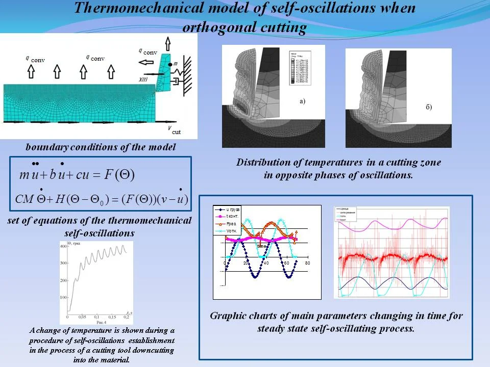
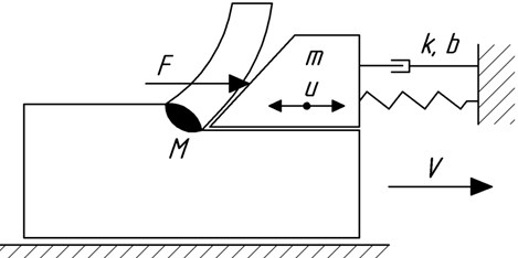
The mathematical model of self-oscillations (Fig. 1) taking into account temperature effects is as follows:
Eq. (1) is the equation of oscillation of the cutter (Fig. 1), where m is the mass of the cutter, is the damping coefficient, is the reduced stiffness, is the cutting force depending on temperature; Eq. (2) – the heat balance equation, where - ambient temperature; is the heated mass; is the specific heat; is the heat transfer coefficient.
This model gives shows the physics of the phenomenon, but it is unsuitable for practical calculations, since it does not take into account the whole complex of processes associated with cutting: elastic and plastic deformation of the workpiece material, destruction of the workpiece material, external friction between the surfaces of the tool, workpiece and shavings, internal friction in the tool material and workpieces, elastic deformation of machine tool system elements, as well as a whole range of thermodynamic phenomena and the accompanying structural transformations in the workpiece material and tool.
Fig. 1Model of the oscillatory system
3. Finite-element model
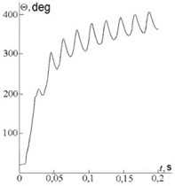
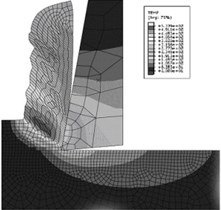
A finite-element model of self-oscillations was obtained in work [7]. As the part of the study of this model, it was made an analysis of the influence of the properties of the processed material, the parameters of the technological system and cutting conditions on the nature and level of vibration during metal cutting. The stability limits are found, the influence of self-oscillations on the shape of the chip is studied, the influence of the thermomechanical properties of the processed material on the nature and intensity of vibration is studied. Fig. 2 shows the boundary conditions of the finite-element model, the curve of temperature fluctuations in the cutting zone and the temperature distribution in the workpiece and tool.
This model is suitable for a deep study of the physical processes occurring in the zone of interaction of the tool and the workpiece. Its disadvantage is the large dimension. To study the dynamic process of development of self-oscillations, a simplified model was formed.
4. Simplified finite-element model
The model allows us to study the conditions of excitation and maintenance of self-oscillations, as well as to assess the influence of process parameters on the amplitude and frequency of these oscillations, without diving into the study of plastic deformation and fracture of the workpiece material. The simplification means that the cutting force arising in the process of plastic deformation, fracture and friction is replaced by an equivalent adhesion force:
where is the proportionality coefficient, and is the force pressing the tool to the workpiece. If we put , where is the average temperature of the contacting surfaces, we obtain a complete mathematical analogy between the adhesion force and the cutting force in the system of Eqs. (1, 2). As you know, the cutting force in a first approximation is directly proportional to the tensile strength of the processed material [8]. Therefore, knowing the dependence of the processed material, it is possible to construct the dependence , and therefore determine the nature of the dependencies and . Table 1 shows the tensile strength of AISI 1045 steel, measured at various temperatures [9].
Fig. 2Boundary conditions and analysis results of the fe-model of self-oscillations during cutting
a)
b)
c)
Table 1Dependence σu=σuΘ for AISI 1045 steel
, °С | 20 | 200 | 400 | 600 |
, mPa | 650 | 670 | 560 | 255 |
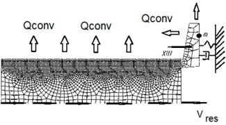
The tensile strength at a higher temperature was determined by interpolation. The problem was solved in a two-dimensional formulation using the abaqus explicit (student edition) program. The oscillation system is represented by an absolutely rigid cube connected to a fixed stand, a weightless elastic-dissipative bond, directed along the axis. The cube is placed on an absolutely rigid plate moving at a constant speed along the same axis. The cube has translational degrees of freedom along the and axes. The necessary weight of the cube, which determines the value of the force pressing the tool against the workpiece, and therefore the value of the adhesion force, was ensured by choosing the appropriate value of the gravitational acceleration. The plate length was chosen in such a way as to minimize the influence of edge effects and to study the process of steady-state self-oscillations. The plate thickness was chosen in such a way as to capture the region of the greatest temperature gradient. The thermodynamic properties of the system are represented by heat capacity, thermal conductivity, as well as the convective heat transfer coefficient of the cube and plate. Between the bodies there is a cohesive force, depending on the temperature on the contact pad. The work of the adhesion force is completely converted into heat, which is distributed between the contacting bodies in proportion to the thermodynamic properties of their materials. The boundary conditions of the model are presented in Fig. 3.
Fig. 3Boundary conditions of the FE model with small amount of computing resources
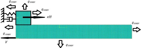
Initial conditions: initial temperature of the system, initial speed of the workpiece.
Since this system consists of absolutely rigid bodies, only thermodynamic and mass properties are included in the model of the processed and tool material (Table 2).
The heat transfer coefficient , which characterizes the intensity of the heat transfer process, depends on a large number of factors related to environmental conditions, geometric parameters of the system and cutting conditions and, generally speaking, is a variable. Its definition is the subject of a separate scientific work. In this study, heat transfer coefficients were chosen in such a way as to ensure a reduction in the transition process time and to be able to observe steady-state oscillations. The heat transfer coefficient is 0.35 for the outer surfaces of the cube and 0.3 m W/(mm2K) for the outer surfaces of the plate.
The model uses 4 -node CPE 4 RT elements with three degrees of freedom (two movements and temperature).
The main difference between the formed FE-model and the analytical model [6] is to take into account the distribution of the temperature field of the workpiece and tool, i.e. replacement of the heat balance Eq. (2) with the heat equation and heat transfer equation. The main difference from the model [7] is the replacement of plastic deformation and fracture by a simplified mathematical analog.
Table 2Properties of tool and processed materials
Density | 7800 kg/m3 |
Thermal conductivity | 45 W/(m°С) |
Heat capacity | 461 J/(kgK) |
5. Conclusions
During the simulation, it was obtained the curves that reflect the law of change in the main parameters of the self-oscillating process from time: tool offset (pos. 1), relative speed of the tool and the workpiece (pos. 2), cutting force (pos. 3), average temperature in contact between tool and chips (pos. 4).
On the graph (Fig. 4), these curves are shown in normalized form for clarity.
Fig. 4Graphs of steady-state oscillations
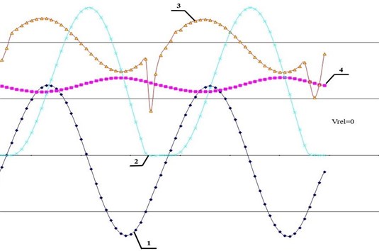
Analysis of the graphs showed that this oscillation has features of both relaxation and quasi-harmonic. On the one hand, the oscillations are almost sinusoidal. On the other hand, the laws of change – cutting force () and – relative speed () show that energy is invested in the oscillatory system only at a moment when the relative speed of the cube and the plate is zero. Thus, the amplitude of self-oscillations is determined by the difference between the coordinates of the “stop” and “stall” of the cube. These graphs are almost identical to the graphs obtained in work [7], which proves the adequacy of the proposed model.
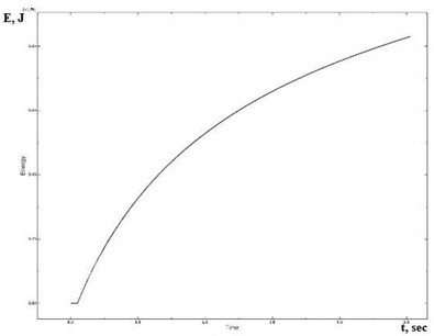
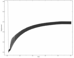
The graph (Fig. 5(a)) shows the dependence of the energy dissipated by convective heat transfer on time for the transient process of cutting the tool into the workpiece. The graph shows that the equality of the input and dissipated energy is achieved in this system, and hence the constancy of the amplitude of the oscillations. In Fig. 5(b) portion of this graph is shown in an enlarged view.
Fig. 5The dependence of the dissipated energy on time
a)
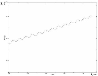
b)
Analyzing the composition of the self-oscillating system we find its main parts: the energy source is an engine that provides a constant plate speed, the oscillating system is a cube on a spring. The role of the buffer is played by the clutch mechanism. Feedback from the oscillatory system to the buffer consists in the fact that the elastic force of the spring determines the breakdown of the cube in its certain position. At the moment when the speeds of the cube and the plate are compared, thermal energy ceases to flow into the system, the temperature of the system begins to decrease. A drop in temperature causes an increase in resistance force.
The influence of cutting conditions, the properties of the technological system and the processed material on the stability during machining are investigated. The model allows us to analyze the influence of excitation conditions on the process of development of self-oscillations. Three cases of excitation of self-oscillations were investigated:
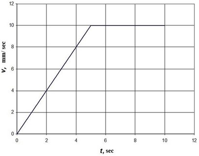
a) The case of “soft excitement”. To simulate “soft excitation” the following law was adopted for the change in the plate velocity with time (Fig. 6). Within 5 seconds, the plate speed increases linearly, then, reaches a steady value.
Fig. 6Graph of change vt
b) The case of “hard excitement”. At the initial moment, the cube was shifted by an amount exceeding the natural level of its vibrations, i.e. the average value of its coordinate during steady-state thermomechanical self-oscillations. After removing this restriction, the process of development of self-oscillations began.
c) Case corresponding to cutting a tool into a workpiece. At the initial time, the cube is in equilibrium, and the plate moves at a constant speed. Then the cube comes into contact with the plate. From the point of view of changes in the forces acting in the system, this case most adequately describes the perturbation caused by cutting the tool into the workpiece.
The laws of cube motion for the described cases are shown in Fig. 7(a, b, c), respectively.
Fig. 7The influence of excitation conditions on the nature of self-oscillations
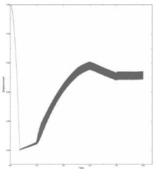
a)
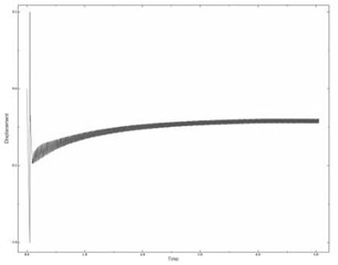
b)
c)
An analysis of these cases showed that the amplitude of self-oscillations, as well as the state of stable dynamic equilibrium, i.e. the average displacement of the cube do not depend on the excitation conditions. Thus, the conditions for the excitation of self-oscillations affect only the time and nature of the transition process. Moreover, the minimum time of the transition process corresponds to the case of hard excitation, which is apparently due to the fact that the additional energy invested in the system by hard excitation is used to heat up the bodies and, as a result, the thermal balance of the system is achieved in a shorter period of time.
The results of the study show that self-oscillations occur only on the falling branch of the curve . Despite the simplicity of the generated model, the conclusions are consistent with the results of field experiments [10]. The values of the amplitudes of self-oscillations during planing of low-carbon steels obtained using the numerical model differ from the experimental results by no more than 15 percent. The dependence of the amplitude of oscillation of cutting speed in both cases has a maximum value in the middle zone (about 20-30 m/min). This model also reveals the physical nature of the phenomena observed in the experiment, which indirectly confirms the hypothesis about the thermomechanical nature of self-oscillations during cutting. The validity of the assumptions and the correctness of the finite element model are confirmed [7]. This work is novel because the proposed model allows us to study different-scale dynamic processes that occur during cutting.
References
-
Kashirin A. I. The Study of Vibrations When Cutting Metals. Academy of Sciences of the USSR, Leningrad, 1944, p. 282, (in Russian).
-
Sokolovsky A. P. Vibrations When Working on Metal Cutting Machines. Study of Vibrations of Metal Cutting Machines When Cutting Metals. Mashgiz, Moscow, 1958, (in Russian).
-
Elyasberg M. E. Fundamentals of the theory of self-oscillations in metal cutting. Machine Tools and Instrument, Vol. 10, Issue 11, 1962, p. 3-8, (in Russian).
-
Kudinov V. A. The Dynamics of Machine Tools. Engineering, Moscow, 1966, p. 359, (in Russian).
-
Tolusty I. Self-Oscillations in Metal-Cutting Machines. Mashgiz, Moscow, 1956, (in Russian).
-
Astashev V. K., Korendyasev G. K. Thermomechanical model of occurrence of self-oscillations during cutting. Problems of Mechanical Engineering and Machine Reliability, Vol. 3, 2012, p. 189-193.
-
Korendyasev G. A thermomechanical model of self-oscillations actuation during metal machining. dynamics of strongly nonlinear systems. Vibroengineering Procedia, Vol. 8, 2016, p. 489-494.
-
Granovsky G. I., Granovsky V. G. Metal Cutting. Higher School, Moscow, 1985, p. 304, (in Russian).
-
Kalhori. Modeling and Simulation of Mechanical Cutting. Ph.D. Thesis, Lulea University of Technology, Sweden, 2001, p. 103.
-
Zharkov I. G. Vibrations when machining with a cutting tool. Engineering, Leningrad, 1987, p. 184, (in Russian).
About this article

This work was done with the support of Russian Science Foundation, Project No. 19-19-00065.
