Abstract
The authors of the study work out to determinate of the mathematical model of supercapacitors as an object of an electric traction system capable of providing non-encumbering of obtaining research results and correct reproduction of energy exchange processes in conditions of repeated-short-term modes of traction load operation. In paper, authors make a comparative assessment of six models for the possibility of their integration into the model of electric traction systems with on-board placement of the energy storage.
Highlights
- The authors work out to determinate of the mathematical model of supercapacitors as an object of an electric traction system capable.
- The authors make a comparative assessment of six models for the possibility of their integration into the model of electric traction systems with on-board placement of the energy storage.
- That the "Simplified model" meets certain criteria of the mathematical model of the energy storage device provided that it is presented as a closed energy storage object with some restrictions.
1. Introduction
The main technical and economic issue in transport today is the regulation and management of power consumption modes [1, 2] in order to optimize the power consumption for traction. At present, one of the options for reducing energy losses is hybridization of electric traction systems, as a result of the use of capacitive energy accumulators, as an additional power source for traction load. Achieving maximum energy efficiency requires the technical solution to provide a simple and simultaneously accurate mathematical model. Against the background of the diversity of mathematical models of capacitive energy storage, today we cannot definitely identify which of the mathematical models should be preferred in the framework of its representation as an object of a hybrid electric traction system, even under specific conditions [3].
To date, among all mathematical models of supercapacitors (SC), four types of models are distinguished - electrochemical, equivalent circuit models, intelligent, and fractional order models. The advantages of electrochemical and fractional models are considered to be the high accuracy of reproducing the behaviour of SC [4, 5]. However, the complexity of the mathematical description and the need for a high level of computation make it difficult to use them. Intelligent models are also a fairly promising variety of models, but there are a number of disadvantages associated with the difficulty of reproducing nonlinear effects and sensitivity to the quality of training data. This problem is very complicated for several railway systems [6-8] and very complicated for marshaling yard with very difficult control and management system in real time [9].
Analysis of works on improving the energy efficiency of electric transport showed that to reproduce the behaviour of capacitive energy storage in most cases, the authors prefer two types of models - models of equivalent circuits and electrochemical models of SC. Models of equivalent schemes have become widespread due to a number of advantages such as ease of parameter identification, the ability to reproduce the characteristics of the behavior of a real object and ease of implementation through the use of conventional differential equations in model formulations. In research, the “Stern model” [10] became the most widespread among electrochemical models as it describes the capacity of the double electric layer of the SC in accordance with the course of physicochemical processes in it, allowing for achieving high accuracy of reproduction of the charge and discharge of the SC.
Summing up, it can be claimed that the arguments given in works [11-13] undoubtedly convince of the possibility of using equivalent and electrochemical models as a model of an energy storage device. However, it is still not clear which criteria to apply when selecting a mathematical model of the SC in the framework of the study of the energy processes of hybrid electric traction systems in conditions of cyclic repeated-short-term operation.
Achieving article goal requires:
– creation of a list of models most used in practice;
– determination of selection criteria;
– carrying out simulation modeling of the specified SC models;
– determination of indicators of accuracy of SC behavior reproduction and verification of the obtained results of simulation with experimental data.
2. Determinate of the mathematical model
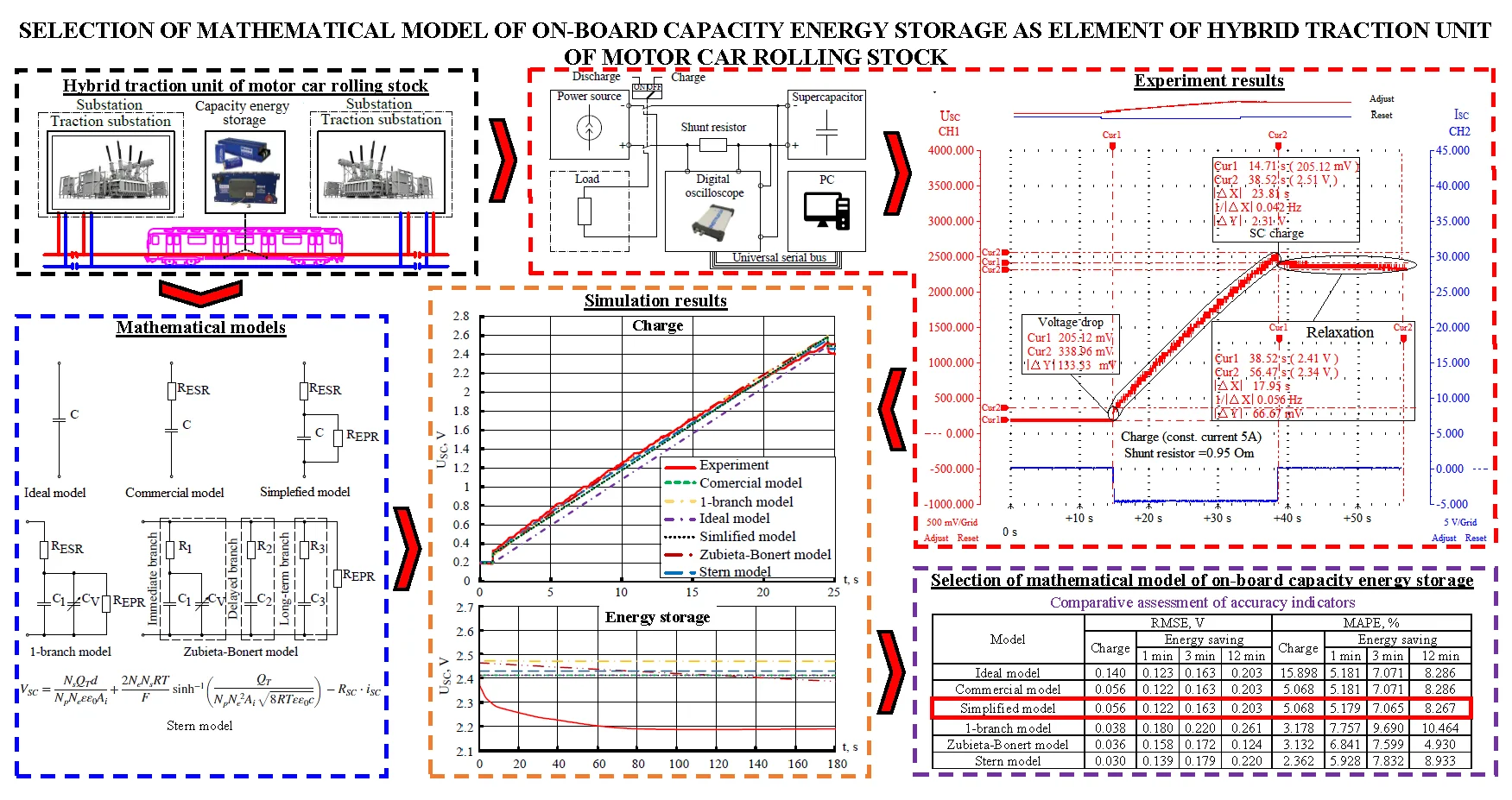
Today, the use of capacitive energy storage (CES) in transport is considered as one of the main ways to achieve energy optimization of traction energy consumption [14, 15]. Each of the concepts in this direction provides for the organization of the management of energy exchange processes. This is especially typical for systems where the on-board CES is used as a tool to reduce the unevenness of traction power consumption. In this case the implementation of an effective management organization is achieved primarily by owning reliable information about the CES parameters and the ability to predict the course of traction and energy processes in the system. The issue of prediction is rather complex, since the leakage of traction and electric braking modes depends on a large number of random factors. As an example, Figs. 1-2 show oscillograms of the voltage and supply current of a subway train when moving on a given inter-station section of a particular day for five weeks at a given time and histograms of the distribution of frequencies of energy renewal values by traction rolling stock of a subway train at various inter-station sections (Fig. 3). The above leads to the formation of a certain zone of uncertainty when deciding to start using the stored energy.
Fig. 1Oscillograms of supply voltage on the current collector of the subway car
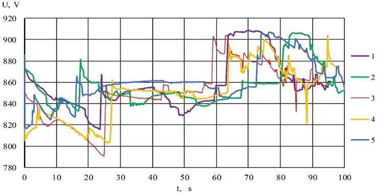
Fig. 2Oscillograms of traction current of the subway train
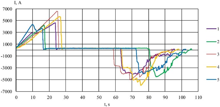
Fig. 3Histograms of frequency distribution of values of power renewal by traction rolling stock of the subway train at various inter-station sections
At the stage of the development of the algorithm control and evaluating the performance of the concept of a hybrid system, along with the existence of a certain zone of non-determinability, there is an additional question of choosing a mathematical model of an energy storage device. On the one hand, it is due to the need to gain reliable information about the value of the amount of stored energy, which would correspond to a real object. On the other hand, we have to present a model as an object of an automatic control system for developing and working out a control algorithm. As practical experience shows, in this case the search for universal mathematical models of SC is unreasonable. Since the desire to create a universal model leads to excessive complexity of the model, leading to limited use of it as a result of the long duration of the simulation, and the need for significant computer memory. The degree of completeness of the model should allow reproducing the behavior of the storage device in the voltage range from 0.5 to the nominal voltage () [16]. That is, the representation of the model as a closed object capable of predicting the behavior of the accumulator in the voltage range from 0.5 to , without reflecting the true connections and internal processes in it, will be sufficient.
Given this, we can claim that the mathematical model of the SC to satisfy the main design and research tacks of the hybrid electric traction system of urban and suburban electric transport must meet three main criteria:
– reliability of information on the value of the volume of stored energy;
– availability of model parameters;
– not burdened by its mathematical description as an object of control.
The implementation of reproducing the behavior of SC by models of equivalent circuits and electrochemical models is significantly different from each other.
In general, the reproduction of the electrical behavior of SC by equivalent circuit models is based on the connection of parameterized RC branches to each other in a certain way. A large number of equivalent scheme models are covered in the scientific literature, but among all models a number of key ones can be distinguished, which are most used in practice. These include the so-called [17, 18] “Ideal model”, “Commercial model”, “Simplified model”, “1-branch model” and the “Zubieta-Bonert model”.
2.1. Ideal model
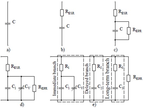
The “Ideal model” is based on an ideal capacitor . The main advantage of this model is simplicity, but its use in research allows us only to obtain a basic understanding of the energy exchange processes between system objects and to form a certain conceptual solution for the use of energy storage devices (Fig. 4(a)).
2.2. Commercial model
The “Commercial model” is the most commonly used SC model, which consists of an ideal capacitor with equivalent series resistance (Fig. 4(b)). Equivalent resistance reproduces the omic losses of the SC in the process of its charge and discharge. This model combines simplicity and sufficient reliability of results in the study of energy storage systems, provided that the simulation of long-term storage of stored energy is not provided.
2.3. Simplified model
The “Commercial model” was supplemented by an equivalent resistor connected in parallel with a capacitor that simulates the process of self-discharge of the SC (Fig. 4(c)). This expands the scope of possible application of this model in the study of long-term energy storage projects. However, this model provides only a basic understanding of the energy exchange processes both in the SC and between the objects of the system as it ignores the important physical phenomena inherent in the SC, such as the process of charge redistribution, the variation of the capacitance depending on the voltage level at the terminals and the recovery process.
2.4. 1-branch model
The “1-branch model” has the advantages of the “Simplified Model” and details the behavior of the SC by taking into account the variation in capacitance in response to a change in voltage on the SC in the practical voltage range of the device (Fig. 4(d)). The variation of the SС capacitance is avoided by using a differential capacitor. The differential capacitor is a capacitor having a parallel connected constant capacitance and capacitance , which depends on the voltage at the differential capacitor. Among the advantages of this model it is possible to distinguish accuracy of reproduction of SC behavior in short-term period of time during cycles of charge and discharge [17].
2.5. Zubieta-Bonert model
The “Zubieta-Bonert model” allows us to reproduce the behavior of the SC in sufficient detail for 30 minutes. [17] (Fig. 4(e)). It is represented by three parallel connected branches (“immediate branch”, “delayed branch”, “long-term branch”) with different time constants that simulate the work of the SC not only in moments of charge or discharge but also reproduce the recovery processes characteristic of the SC and charge redistribution. “Immediate branch” is a differential capacitor (parallel connected constant capacitance and capacitance , which depends on the voltage on the differential capacitor) and resistor . “Immediate branch” predominates in the reproduction of the behavior of the SC in the range of seconds in response to a charge or discharge [17, 18]. “Delayed branch” is a series-connected capacitor and resistor . “Delayed branch” predominates in the reproduction of the behavior of the SC in the range of minutes [17, 18]. “Long-term branch” is a series-connected capacitor and resistor . “Long-term branch” predominates in the reproduction of the behavior of the SC for more than 10 minutes [17, 18]. It should be added that the specificity of this type of mathematical models is to cover only a certain period of time of the SC, thus requiring a clearly defined time interval between the phases of the energy storage such as energy storage and return.
Fig. 4Equivalent circuit models of the SC: a) Ideal model; b) Commercial model; c) Simplified model; d) 1-branch model; e) Zubieta-Bonert model, where C – ideal capacitor; RESR – equivalent series resistance; REPR – equivalent parallel resistance; C1 - fixed capacitance differential capacitor; CV – voltage-dependent capacitance of the differential capacitor; R1, R2, R3 – resistance of branches Immediate branch, Delayed branch, Long-term branch accordingly; C2, C3 – capacitor of branches Delayed branch, Long-term branch accordingly
2.6. Stern model
“Stern model” is able to reproduce the change in the capacity of the SC, in accordance with the nonlinear dynamics of diffusion in it. The capacity of the SC is determined by two components – the Hermholtz capacity and the diffusion capacity. The Hermholtz capacity is a constant component of the SC capacity and depends only on its physical parameters.
The diffusion capacity varies according to the change in the concentration of ions in the electrolyte solution as a result of diffusion and electrostatic forces. The key feature of this model is a detailed reproduction of the processes of charge and discharge of the SC due to the mathematical description of the physicochemical processes occurring in it. As for the mathematical description, each model, in accordance with the attempt to detail the behaviour of the SC, has its own level of complexity. Table 1 shows the mathematical models of those mentioned above.
Table 1Mathematical models of SC
Name | Mathematical model | |
Ideal model | ||
Commercial model | ||
Simplified model | ||
1-branch model | – coefficient, the dependence of the capacitance of the SC relative to the voltage at its terminals | |
Zubieta-Bonert model | ||
Stern model |  | – interfacial area between electrodes and electrolyte – molar concentration – molecular radius – faraday constant – electric charge – ideal gas constant – operating temperature – permittivity of material – permittivity of free space – number of layers of electrodes – number of parallel supercapacitors – number of series supercapacitors |
However, for each of the above models, there are limitations concerning their ability to adequately reproduce the behaviour of the SC only for certain time intervals under certain conditions and for specific purposes. On the grounds of the analysis, Table 2 shows the main advantages and disadvantages of the models under consideration and the directions of possible application in conducting the studies.
In most cases, the time interval of the SC operating cycle provides for three phases – charge, discharge and energy storage. If the reproduction of the charge and discharge phases of the SC model does not need to be clarified in terms of the time interval of their course, then the duration of the energy storage phase plays an important role in the reliability of the simulation results. Firstly, this is due to the possibility of SC models to adequately reproduce the behaviour in this phase only in certain time frames, and secondly, partial or even complete neglect of some models of physical processes of SC in this phase. In general, the duration of the energy storage phase is determined by the concept of reuse of stored energy and spatial location of the drive. For the stationary placing, the range of possible duration of the energy storage phase will be formed by the train schedule. In the case of on-board placement, as shown by the results of studies [5, 14, 15], the appropriate use of stored energy is its focus on optimizing the peak of traction energy consumption, i.e. use in the time of the acceleration vehicle. Under these conditions, the storage phase of the charge will correspond to the stopping time of the rolling stock at the station (Fig. 5).
Table 2Characteristics of mathematical models of SC
Model | Advantages | Disadvantages | Areas of possible application |
Ideal model | 1. Simplicity 2. The availability of model parameters | 1. Low accuracy 2. Ignores physicochemical and electrical processes in the SC | Basic understanding of energy flow of exchange processes between hybrid system facilities |
Commercial model | 1. Simplicity 2. The availability of model parameters 3. Reproduction of electrical losses | 1. Low accuracy 2. Ignores physicochemical processes in the SC 3. No imitation of self-discharge | Estimation of energy losses; simulation of the thermal state of a capacitive energy storage |
Simplified model | 1. The availability of model parameters 2. Reproduction of electrical losses 3. Reproduction of self-discharge | 1. Effect of electric potential change due to charge redistribution is not taken into account | Formation of technical solution for use of SC as energy storage; simulation of hybrid systems with short-term energy storage cycle |
1-branch model | 1 Accuracy of reproduction of SC behavior in a short period of time 2. Reproduction of capacity change as a result of diffusion processes | 1. Need for high accuracy experimental studies 2. Ignores the processes of charge redistribution and recovery | Simulation of hybrid systems where the supercapacitor energy storage is considered a device for energy storage without the need for its long-term storage |
Zubieta-Bonert model | 1. Reproduction of long-term behavior 2. Possibility of predicting the stationary voltage level at the SC leads | 1. Need for high accuracy experimental studies | Modeling of hybrid systems, where supercapacitor energy storage is considered as backup power supplies and devices for storing excess energy with an unpredictable energy exchange cycle |
Stern model | 1. High accuracy of charge and discharge reproduction of the SC | 1. High complexity of the model 2. The need for in-depth research to determine the parameters of the model | Modeling hybrid systems where accurate understanding of stored energy is needed, without the need for long-term storage |
In this paper, we make a comparative assessment of the above six models for the possibility of their integration into the model of electric traction systems with on-board placement of the energy storage. During the study, a number of assumptions were made that the accuracy of reproduction of SC discharge models is identical to its charge within one cycle “charge-discharge” and the time of the energy storage phase will not exceed 3 minutes. A supercapacitor with a capacity of 50 Faraday of nominal voltage 2.7 V is considered as a test sample. The parameters given in [18] and the technical documentation of the test sample were taken as the basis of the model parameters. The parameters of certain mathematical models are given in Table 3.
The square root of the root mean square error (RMSE) and the mean absolute percentage error (MAPE) were used as indicators of the accuracy of reproducing the behaviour of the SC:
where – the -th value of the estimation parameter of the model; – the -th true value of the evaluation parameter; – the number of measurements of the evaluation parameter.
Fig. 5Phases of operation of the energy storage in the case of its onboard placement while optimizing the peak of traction power consumption of the subway electric train
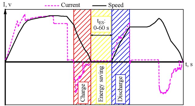
Table 3Parameters of mathematical models of equivalent schemes
Name | Parameter | Value | Units of measurement |
Ideal model | 50 | Faraday | |
Commercial model | 50 | Faraday | |
0,02 | Om | ||
Simplified model | 50 | Faraday | |
0.02 | Om | ||
36000 | Om | ||
Zubieta-Bonert model | 42.5 | Faraday | |
5.1 | Faraday / V | ||
0.016 | Om | ||
10.5 | Faraday | ||
112 | Om | ||
4 | Faraday | ||
628 | Om | ||
36000 | Om | ||
Stern model | 50 | Faraday | |
0.02 | Om | ||
2.7 | V | ||
25 | °C |
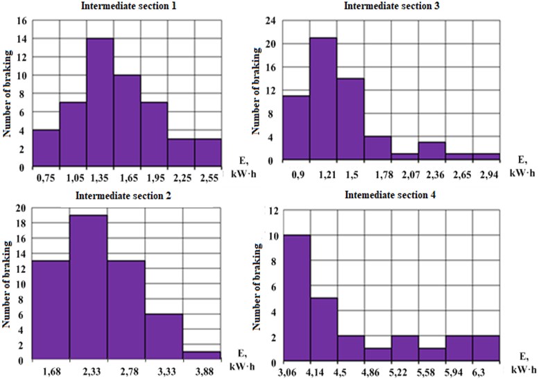
The evaluation parameter for which the comparison was performed is the data of the instantaneous value of the voltage at the SC terminals, obtained during the simulation. The real value was the instantaneous value of the voltage at the outputs of the experimental sample , obtained during experimental studies (Figs. 6-8).
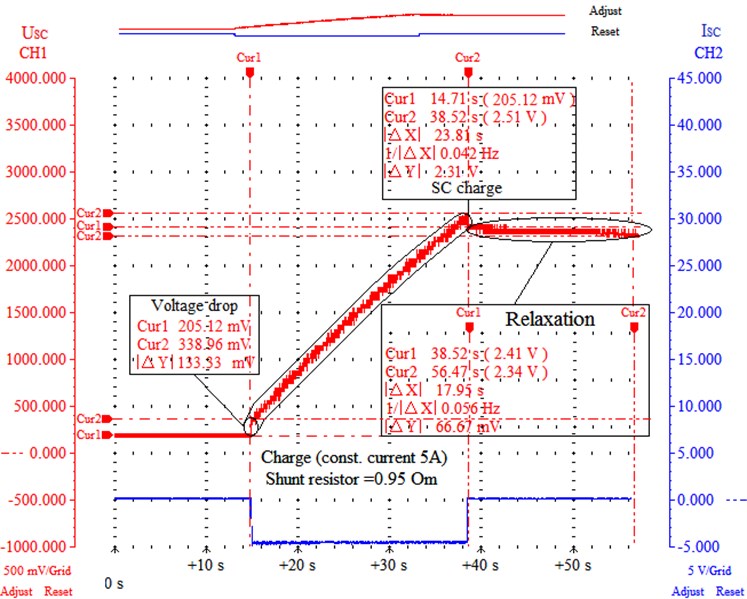
The phase of SC charge was carried out with a constant current ISC at the level of 5 A in the operating voltage range from 0.2 V (Cur1) to 2.5 V (Cur2) (Fig. 6). The value of 0.2 V is the relative complexity of the use of all stored energy in a short period of time. In this case, time of SC charge lasted || 23.81 s.
Fig. 6Experimental results of the SC charge phase: USC – voltage at the terminals of the prototype SC; ISC – charge current of the prototype SC; CH1, CH2 – 1 and 2 oscillograph channels, respectively; Relaxation – redistribution of charge in the structure of the SC at the end of the charge phase; Cur1, Cur2 – 1 and 2 measurement cursor respectively; |ΔX| – absolute value of difference in time (along x axis) between Cur1 and Cur2; |ΔY| – absolute value of difference in amplitude signals between Cur1 and Cur2
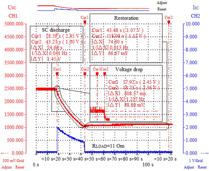
The phase of SC discharge was carried out in the range from 2.45 V (Cur1) to 1 V (Cur2) at a constant load with a resistance of 0.5 Om (Fig. 7). In this case, time of SC discharge || lasted 24.7 s.
Based on the experimental results of measuring the voltage drop values ||, it was found that the internal series resistance of the is 0.027 Om (Fig. 6, 7). It was also found the presence of variation in the value of in the range of 3-7 % due to changes in charge intensity, the number of continuous cycles “charge-discharge” or the occurrence of disturbances, whether a sharp drop in charge current (Fig. 6, 7; Table 3).
In the course of experimental studies, the presence of charge redistribution in the middle of the SC after the phases of charge (relaxation) and discharge (restoration) of the drive was confirmed (Fig. 6-8). In Fig. 8 shows the oscillograms of the change in the instantaneous voltage of the at the terminals of the SC due to the processes of relaxation and restoration for the time interval || 180 seconds at Cur1 and Cur2 measurement cursors. For the experimental results within the measurement cursors Cur1 and Cur2, the voltage change range || reached 7-8 %. According to the obtained results, we can state that the key factor that determines the instantaneous value of the SC voltage is mainly the stage of charge redistribution within the SC. Thus, it is somewhat incorrect to use self-discharge in models as a tool for reproducing the relaxation of the SC, because in the process there is no loss of accumulated energy but only its redistribution within the SC itself. Without a doubt, it is impossible to exclude the self-discharge of the SC, but the importance of its influence on the formation of the voltage level is not so great.
Fig. 7Experimental results of the discharge phase of the SC: USC – voltage at the terminals of the prototype SC; ISC – discharge current of the prototype SC; CH1, CH2 – 1 and 2 oscillograph channels, respectively; RLOAD – load resistance SC; Restoration – charge redistribution in the SC structure at the end of the discharge phase; Cur1, Cur2 – 1 and 2 measurement cursor respectively; |ΔX| – absolute | value of difference in time (along x axis) between Cur1 and Cur2; |ΔY| – absolute value of difference in amplitude signals between Cur1 and Cur2
Our experimental setup included a SC, a data acquisition system, a power supply, a current shunt, and a load (Fig. 9). The SC was used by SAMWHA DS series with a capacity of 50 F. A switching power supply with the function of limiting the output current was used as a source of constant power. Data collection was performed using a two-channel digital oscilloscope Instrustar ISDS 205A and software Record Recorder Multi VirAnalyzer. The sampling frequency of the sampling signal is 1 MHz. The load and current shunt are implemented on ceramic resistors with a scattering power of 5 watts.
The processing of the results of experimental data to isolate the based signal was carried out using the Signal Analyzer application of the Matlab software product. The comparative evaluation was carried out on the basis of the results of the simulation of the Matlab software product using the Simscape Electrical physical systems modeling package of the Simulink graphical simulation environment [19]. The “Stern model” was implemented by the “Supercapacitor” Matlab block using the predefined model parameters given in the block. As a numerical integration algorithm, a discrete time with a fixed sampling period of 0.001 s was used. Experimental data were presented in the form of a table function. When performing a comparative evaluation of mathematical models with experimental data in the examined dependent variable, the instantaneous value of stress at SC terminals was determined. As an independent variable for carrying out a comparative evaluation of the reproduction of the charge phase of SC, mathematical models are the charge current of SC at the level of 5 A. For the storage phase of stored energy, the time of the storage phase of stored energy within 3 minutes is selected as an independent variable. Figs. 10 and 11 show the results of the simulation of the charge and storage phases of each model. The parameters given in Table 3 were used as model parameters.
Fig. 8Experimental results of the energy storage phase of the SC: USC – voltage at the terminals of the prototype SC; CH1, CH2 – 1 and 2 oscillograph channels, respectively; Relaxation – redistribution of charge in the structure of the SC at the end of the charge phase; Restoration – charge redistribution in the SC structure at the end of the discharge phase; Cur1, Cur2 – 1 and 2 measurement cursor respectively; |ΔX| – absolute value of difference in time (along x axis) between Cur1 and Cur2; |ΔY| – absolute value of difference in amplitude signals between Cur1 and Cur2
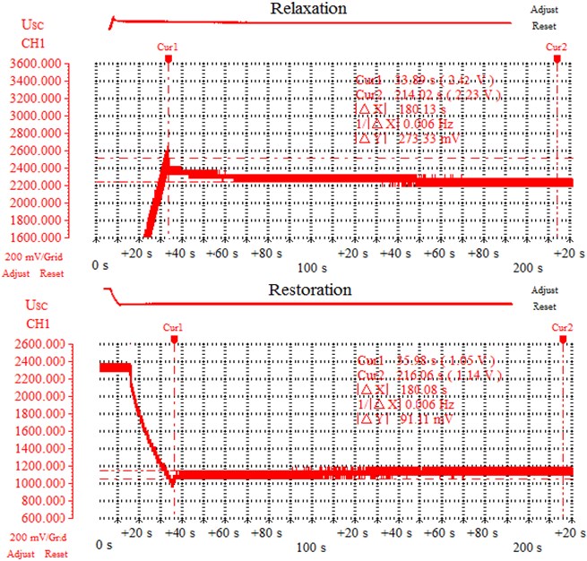
Fig. 9Structural diagram of test platform of SC
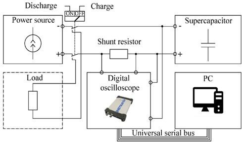
Fig. 10Comparative evaluation of mathematical models of SC during the charge phase: USC – voltage at the terminals of the SC, error – models error of the SC
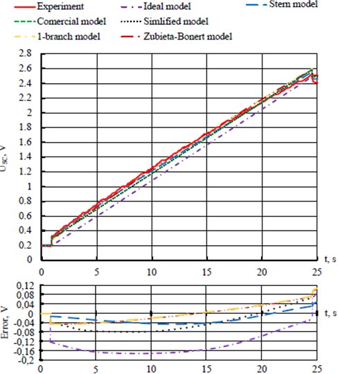
Fig. 11Comparative evaluation of mathematical models of SC during the energy storage phase: USC – voltage at the terminals of the SC, error – models error of the SC
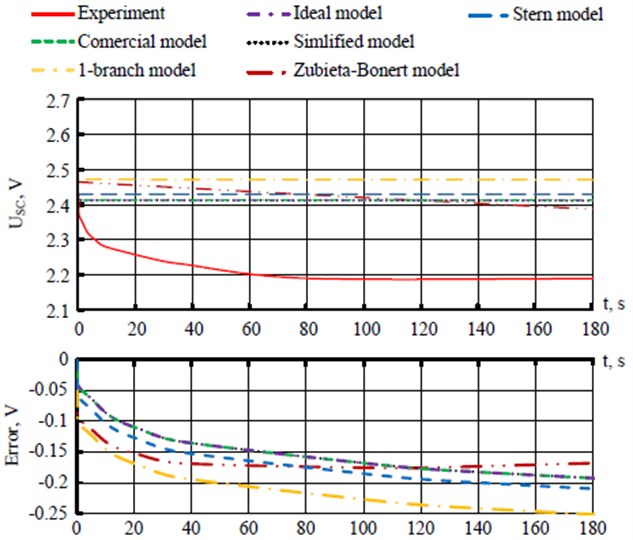
In Fig. 11, we can observe the reproduction of the charge storage phase models. For all models except the “Zubieta-Bonert model”, the change in no-load voltage at the SC terminals is practically absent, because, as noted earlier, these models do not simulate the internal process of charge redistribution.
After analyzing the resulting simulation results and comparing them with experimental data, RMSE and MAPE accuracy measures were calculated and structured in Table 4. RMSE gives relatively great weight to significant errors, which will prevent further distortion of information about the value of the stored energy volume. MAPE has a more supervisory meaning and eliminates the problem of mutual compensation for positive and negative errors. Thus, the use of these accuracy indicators will reduce the likelihood of making a false decision. Determination of RMSE and MAPE was carried out for two separately separated phases of the SC cycle (charge, energy storage). The SC discharge phase was not considered as previously assumed. The accuracy of energy storage phase reproduction was considered within two time intervals of 1 and 3 minutes. This was done to give greater objectivity to the decision made when giving advantage to a particular model, either for hybridization of suburban rail electric transport or traction rolling stock of the subway. A longer storage phase was also determined with a time interval of 12 minutes. The time of 12 minutes corresponds to 95 % cases of travel time between stations by suburban railway transport in Ukraine.
Table 4The values of the accuracy of the reproduction of the behavior of the SC
Model | RMSE, V | MAPE, % | ||||||
Charge | Energy saving | Charge | Energy saving | |||||
1 min | 3 min | 12 min | 1 min | 3 min | 12 min | |||
Ideal model | 0.140 | 0.123 | 0.163 | 0.203 | 15.898 | 5.181 | 7.071 | 8.286 |
Commercial model | 0.056 | 0.122 | 0.163 | 0.203 | 5.068 | 5.181 | 7.071 | 8.286 |
Simplified model | 0.056 | 0.122 | 0.163 | 0.203 | 5.068 | 5.179 | 7.065 | 8.267 |
1-branch model | 0.038 | 0.180 | 0.220 | 0.261 | 3.178 | 7.757 | 9.690 | 10.464 |
Zubieta-Bonert model | 0.036 | 0.158 | 0.172 | 0.124 | 3.132 | 6.841 | 7.599 | 4.930 |
Stern model | 0.030 | 0.139 | 0.179 | 0.220 | 2.362 | 5.928 | 7.832 | 8.933 |
A comparative evaluation of the RMSE and MAPE (Table 4) found the following. All models, except the “Ideal model”, reproduce the SC charge with high accuracy. For these models, the MAPE for the charge phase is in the range from 2.4 to 5.1 % (Table 4). According to Table 4, taking into account the presence of SC diffusion capacity in the models “1-branch model”, “Zubieta-Bonert” and “Stern model” allows to improve the adequacy of the reproduction of the charge phase almost 2 times compared to other models considered. Based on the accuracy indicators of RMSE and MAPE (Table 4), it can be argued that the reproduction of the charge redistribution process by the Zubieta-Bonert model in short-term energy storage phases up to 3 minutes does not significantly increase the adequacy of the model compared to other models, but only allows to achieve high accuracy. The main problem of the “Zubieta-Bonert” and 1-branch model models is their indirect determination of model parameters, based on the results of preliminary experimental studies of the original object.
From RMSE and MAPE (Table 4) it follows that “Simplified model” and “Stern model” provide the highest accuracy of reproduction of charge phases and energy storage in a time interval up to 3 minutes. Based on the accuracy of RMSE and MAPE (Table 4), it can be argued that the reproduction of the charge redistribution process model “Zubieta-Bonert” in the short phases of energy storage up to 3 minutes does not significantly increase the adequacy of the model compared to other models, but only achieves high accuracy in concepts with long-term energy storage. The main problem of the “Zubieta-Bonert” and “1-branch” models is their indirect determination of the model parameters, based on the results of previously conducted experimental studies of the original object. From RMSE and MAPE (Table 4) it follows that “Simplified model” and “Stern model” provide the highest accuracy of reproduction of charge phases and energy storage in a time interval up to 3 minutes. In this case, the majestic charge phase error (Fig. 6) for “Simplified model” and “Stern model” does not exceed 0.08 V and 0.05 V, respectively. Therefore, these models do not significantly distort the information about the amount of energy stored after the charge or discharge. For the energy storage phase after 180 s the magnitude of the error (Fig. 7) reaches 0.19 V and 0.21 V, respectively. At the same time, the results of experimental studies show that the transient process of changing the energy states of the SC after the completion of the charge or discharge phase has a similar nature and leads to a change in voltage at the terminals of the SC in a certain range (Fig. 8). This allows, using predefined constants or time functions, to increase the accuracy of models in the storage phase, without resorting to the complexity of a particular model. This will be sufficient for a closer understanding of the amount of “quickly available” energy and additional energy input due to the subsequent change in the energy state of the SC for recovery after the discharge phase.
If you look at the models in terms of availability of their parameters, the advantage of “Simplified model” is indisputable as the parameters of this model are in common use and are provided by each manufacturer. For the “Stern model” the situation is a bit more complicated, because the mathematical model operates with somewhat specific parameters. Thus, there are developments that allow us to model the SC on the grounds of pre-defined parameters of the model, but this does not give confidence in the reliability of the results without additional experimental studies. However, the possibility of mathematical description of these models as a control object is not significantly difficult. However, the mathematical description of the “Stern model” has a higher level of complexity due to the presence of a hyperbolic function in the mathematical model as opposed to the “Simplified model”.
So, “Simplified model” meets all our criteria and can be presented as a mathematical model of the SC object of the electric traction system under conditions of briefly long cycles of the energy storage. In our opinion, the accuracy of reproducing the SC behavior, taking into account the above steps to assess the energy state of the SC during the charge storage phase, will be sufficient to possess reliable information about the instantaneous value of the stored energy volume and simulate the course of traction-energy processes in the electric traction system of urban and suburban electric transport. However, this model will not allow to correctly simulate the operation of power accumulators of main trains. However, this model will not correctly simulate the operation of power storage of main trains in the case of long-term energy storage.
3. Conclusions
Based on the results of the comparative evaluation, it was found out that the “Simplified model” meets certain criteria of the mathematical model of the energy storage device, provided that it is presented as a closed energy storage object, which has processes of energy accumulation and recoil with cyclic repeatability without a long-term energy storage phase within one charge-discharge cycle.
The main disadvantage of mathematical models of SC is the inability to reproduce physical and chemical processes of SC occurring during the energy storage phase. During the analysis of experimental data, it was found out that it is incorrect to use self-discharge in models as a tool for reproducing SC relaxation since this does not lead to irreversible losses of stored energy, but only to its redistribution within the SC itself.
Presence of SC reaction to change of charge intensity, number of continuous cycles “charge-discharge” or occurrence of sharp disturbances, in the form of change of its internal equivalent resistance within 3-7 % is established (Fig. 6, 7; Table 3). At the same time, the change in value was random.
References
-
Muhitovs R., Mezitis M., Freimane J. Intelligent railway point electric heating control system. 60th Annual International Scientific Conference on Power and Electrical Engineering of Riga Technical University, 2019, https://doi.org/10.1109/RTUCON48111.2019.8982345.
-
Muhitovs R., Mezitis M., Korago I. Development of the railway point electric heating intellectual control algorithm. Transport Problems, Vol. 15, Issue 1, 2020, p. 71-79, https://doi.org/10.21307/TP-2020-007.
-
Eddahech A., Ayadi M., Briat O., Vinassa J.-M. Online parameter identification for real-time supercapacitor performance estimation in automotive applications. International Journal of Electrical Power and Energy Systems, Vol. 51, 2013, p. 162-167, https://doi.org/10.1016/j.ijepes.2013.03.001.
-
Sharma P., Hu, Bhatti T. S. A review on electrochemical double-layer capacitors. Energy Conversion and Management, Vol. 51, Issue 12, 2010, p. 2901-2912, https://doi.org/10.1016/j.enconman.2010.06.031.
-
Yatsko S., Sidorenko A., Vashchenko Ya., Lyubarskyi B., Yeritsyan B. Method to improve the efficiency of the traction rolling stock with onboard energy storage. International Journal of Renewable Energy Research (IJRER), Vol. 9, Issue 2, 2019, p. 848-858.
-
Nikolajevs A., Mezitis M. Level crossing time prediction. International Scientific Conference on Power and Electrical Engineering of Riga Technical University, 2016, https://doi.org/10.1109/RTUCON.2016.7763105.
-
Muhitovs R., Mezitis M., Freimane J., Korago I. Development of the decision-making algorithm for railway maneuverer park equipment with independent controllers. Procedia Computer Science, Vol. 149, 2019, p. 202-205, https://doi.org/10.1016/j.procs.2019.01.124.
-
Freimane J., Mezitis M., Mihailovs F. Maneuver movements' safety increase using maneuver locomotive identification and distance control. Procedia Computer Science, Vol. 104, 2016, p. 375-379, https://doi.org/10.1016/j.procs.2017.01.148.
-
Mezitis M., Panchenko V., Kutsenko M., Maslii, A. Mathematical model for defining rational constructional technological parameters of marshalling equipment used during gravitational target braking of retarders. Procedia Computer Science, Vol. 149, 2019, p. 288-296, https://doi.org/10.1016/j.procs.2019.01.137.
-
Oldham K. B. A Gouy-Chapman-Stern model of the double layer at a (metal)/(ionic liquid) interface. Journal of Electroanalytical Chemistry, Vol. 613, Issue 2, 2008, p. 131-138, https://doi.org/10.1016/j.jelechem.2007.10.017.
-
Szenasy I. Energy management and hybrid energy storage in metro railcar. International Conference on Renewable Energy Research and Applications 2012, https://doi.org/10.1109/ICRERA.2012.6477423.
-
Streit L., Talla J., Drabek P. Economic comparison of basic energy storage system control strategies. in Proc. Proceedings of the 16th International Conference on Mechatronics – Mechatronika, Vol. 2014, 2014, p. 662-665, https://doi.org/10.1109/MECHATRONIKA.2014.7018339.
-
Miniguano H., Barrado A., Raga C., Lázaro A., Fernández C., Sanz M. A comparative study and parameterization of supercapacitor electrical models applied to hybrid electric vehicles. International Conference on Electrical Systems for Aircraft, Railway, Ship Propulsion and Road Vehicles & International Transportation Electrification Conference 2016, https://doi.org/10.1109/ESARS-ITEC.2016.7841354.
-
Yatsko S., Sytnik B., Vashchenko Ya., Sidorenko A., Liubarskyi B., Veretennikov I., Glebova M. Comprehensive approach to modeling dynamic processes in the system of underground rail electric traction. Eastern-European Journal of Enterprise Technologies, Vol. 1, Issue 9, 2019, p. 48-57, https://doi.org/10.15587/1729-4061.2019.154520.
-
Yatsko S., Sydorenko A., Vashchenko Ya. Development of strategies for reducing traction energy consumption by electric rolling stock. Computational Problems of Electrical Engineering Journal, Vol. 1, Issue 9, 2019, p. 44-52.
-
Ceraolo M., Lutzemberger G., PoliD. State-of-charge evaluation of supercapacitors. Journal of Energy Storage, Vol. 11, 2017, p. 211-218, https://doi.org/10.1016/j.est.2017.03.001.
-
Zubieta L., BonertR. Characterization of double-layer capacitors for power electronics applications. in Proc. IEEE Transactions on Industry Applications, Vol. 36, Issue 1, 2000, p. 199-205, https://doi.org/10.1109/28.821816.
-
Mishra D., DeS. Effects of practical rechargeability constraints on perpetual rf harvesting sensor network operation. IEEE Access, Vol. 4, 2016, p. 750-756, https://doi.org/10.1109/ACCESS.2016.2528822.
-
Mathworks, https://www.mathworks.com/products/simscape.html.
About this article

