Abstract
Building facades are becoming more and more complex, and the requirements for concrete quality on the facades are increasing. Traditional slipforming construction is difficult to meet the requirements of construction period and quality. Incremental slipforming with sliding frame has emerged at the historic moment. Due to the heavy weight of hydraulic incremental slipforming platform with sliding frame and the complicated force condition, the research on its safety and stability is particularly necessary. Aiming at the construction needs of the complex frame-shear wall rectangular chimney project, a new type of platform of hydraulic incremental slipforming with sliding frame is proposed. According to the platform structure design composition and construction technology, the finite element model of hydraulic incremental slipforming platform with sliding frame was established in the ANSYS platform. The stress and displacement of hydraulic incremental platform slipforming with sliding frame under different working conditions were studied through static analysis. The dynamic characteristics of the structure were obtained through modal analysis, and the safety and stability of hydraulic incremental slipforming platform with sliding frame were evaluated.
1. Introduction
There are flaws in traditional slipforming construction technology [1]: 1) The construction organization has high requirements. Slipforming construction must be operated continuously, otherwise it will be difficult to slip. 2) When the structure facade is complex and the structure changes, the efficiency of the formwork system is greatly reduced. 3) The concrete surface will produce cracks, run-out, slip marks, honeycomb pockmarks, etc. In response to the above shortcomings of slipforming construction, hydraulic incremental slipforming with sliding frame (hereinafter called 'HISSF') came into being. HISSF [2] means that the lifting equipment drives sliding frame composed of lift yoke, form walers and climbing rod to slide along the outer surface of the formwork (there is no relative sliding between formwork and concrete). When the formwork comes out from the lower side of the sliding frame, take out the formwork and install it on the upper side of the sliding frame again. Pour the concrete again and raise the sliding frame, and then recycling operations complete the construction of the concrete structure. HISSF combines the advantages of slipforming construction and turning-over formwork construction. The construction progress and construction quality are guaranteed.
At present, many scholars have conducted a lot of research on slipforming construction from different angles. T. Brockmann [3] introduced the development and application of slipforming construction, and provided practical recommendations for the correct application of the slipforming construction. G. E. Mohammadi [4] introduced a novel symbolic regression method called biogeography-based programming and applied for extracting a formula that obtains a good climbing rate of slip formwork systems. Other scholars [5, 6] studied and improved the fluidity and consolidation properties of concrete, thereby improving the quality of slipform construction. M. Lachemi [7] simulated the thermal behavior of concrete during the slipforming molding process through a numerical program, and found that the shape of the “hardening front” is affected by the temperature of the fresh concrete and environmental conditions. H. A. Abdel-Khalek [8] used Discrete-event simulation to determine the most effective parameters affecting the duration of slipforming, and proposed a DES model for predicting the period of slipforming construction. The above research mainly focuses on the application of slipforming construction, crafts improvement, exploration of factors affecting sliding speed, etc., but less attention is paid to mechanical analysis of construction platform. The platform of hydraulic incremental slipforming with sliding frame (hereinafter called “HISSF platform”) has a large weight and complicated condition, and it is in a floating state during construction. So its mechanical properties and safety analysis are particularly important. A finite element model of HISSF platform was established for static and modal analysis. The safety of the HISSF platform was evaluated and successfully applied, which also provided reference for the design and construction of similar projects in the future.
2. Composition of HISSF platform
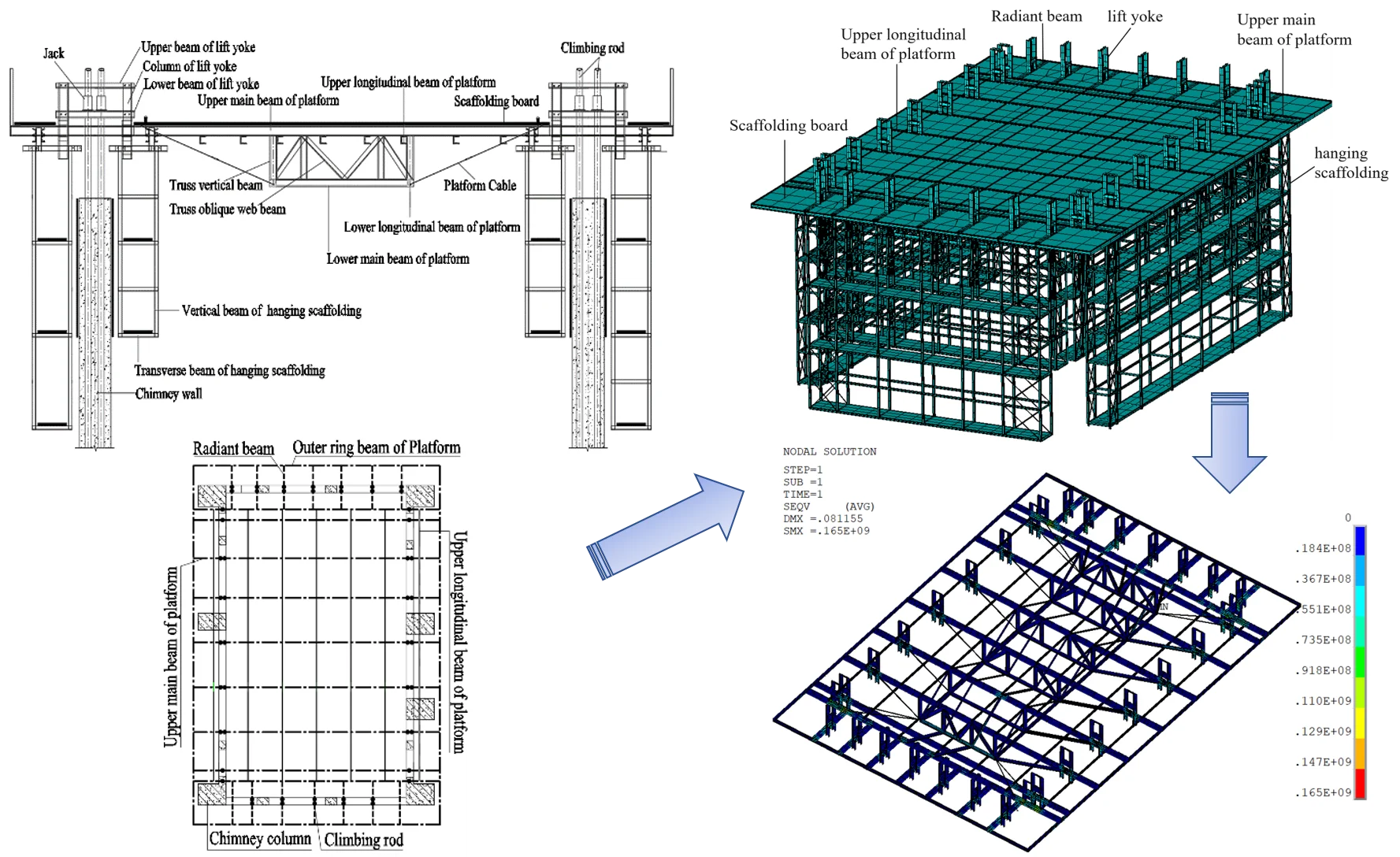
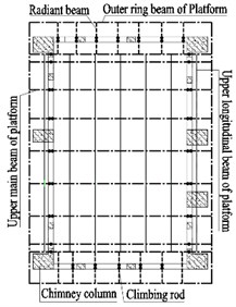
HISSF platform system is composed of hydraulic sliding system, operation platform system, formwork system. The structure of HISSF platform is shown in Fig. 1. The hydraulic sliding system is composed of φ48×5mm climbing rod, GYD-60 hydraulic jack, YKJ-36 hydraulic control unit, etc. The operating platform system consists of a central drum ring, platform planking, protective railings, and hanging scaffolding. nine 2[14a channel steel upper main beams, seven [8a channel steel upper longitudinal beams, fourteen 2[14a channel steel radiant beams to form the platform framework. The formwork system consists of lift yoke, inner and outer formwork and diameter adjusting device. The formwork adopts 1500 mm×900 mm×15 mm woodworking formwork. The cross-sectional view of the HISSF platform is shown in Fig. 1, and the plan is shown in Fig. 2.
Fig. 1Sectional view of HISSF platform
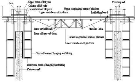
Fig. 2Plane graph of HISSF platform
3. Establishment of finite element model
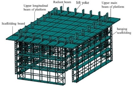
The HISSF platform of the chimney is heavy in weight and complicated in force. This paper chooses to use ANSYS finite element software to establish an overall model of the HISSF platform for analysis.
3.1. Establishment of geometric model
The HISSF platform structure is composed of a variety of channel steel, angle steel and round steel with different cross-sectional dimensions. The whole model uses three element types: SHELL63, LINK10 and BEAM188. The 4-node elastic shell element SHELL63 can bear in-plane and normal loads. The platform scaffolding board adopts SHELL63 element. The tensioning steel bars on the platform cable and hanging scaffold adopt 3D tension-only unit LINK10. The rest of the components all use 3D linear finite strain BEAM188 beam element [9], BEAM188 is a three-dimensional linear strain beam element, suitable for analyzing beam structures ranging from slender to medium short and thick. The main unit parameters of HISSF platform members are shown in Table 1.
Table 1Main unit parameters of HISSF platform members
No. | Structural member | Material | Geometric parameter(mm) | Element |
1 | Climbing rod | Round tube steel | D 48×5 | Beam188 |
2 | Radiant beam | Channel steel | 2[140×58×6 | Beam188 |
3 | Upper main beam of platform | Channel steel | 2[140×58×6 | Beam188 |
4 | Upper longitudinal beam of platform | Channel steel | [80×43×5 | Beam188 |
5 | Outer ring beam of Platform | Channel steel | [126×53×5.5 | Beam188 |
6 | Truss vertical beam | Channel steel | [140×58×6 | Beam188 |
7 | Truss oblique web beam | Angle | ∟63×6 | Beam188 |
8 | Scaffolding board | Board | H 0.05 | Shell63 |
9 | Platform Cable | Round rebar | ∅18 | Link10 |
10 | Round steel support | Round rebar | ∅16 | Link10 |
*D – Round tube steel outer diameter×thickness; [ – channel steel height×width×waist thickness; ∟ – angle steel side width×side thickness; H – scaffolding board thickness; ∅ – round rebar diameter | ||||
3.2. Boundary conditions
The climbing rods is used as the slide rail of the HISSF platform. The hydraulic jack climbs up along the climbing rods, driving the entire HISSF platform to slide up. During the whole construction process, the climbing rods and the stressed steel bars are poured into the concrete body together as the load-bearing components of the structure. The height of the formwork is 1.5 m. After the concrete has been poured to reach early compressive strength of 0.8 N/mm2, the HISSF platform climbs 1.5 m, and the bottom of the jack is 900 mm from the top of the formwork. Therefore, the length is 2.4 m of the climbing rod can be used for modeling calculation. When the early compressive strength reaches 0.8 N/mm2, the concrete’s embedding constraint on the climbing rod has been formed [10], so the lower end of the climbing rod can be considered as a fixed support. The lower part of the HISSF platform hanging scaffolding is overlapped with the chimney wall structure, and its horizontal displacement is constrained. In the model, the boundary condition is expressed as the -direction sliding hinge constraint. The finite element model is shown in Fig. 3.
Fig. 3Finite element model of HISSF platform
3.3. Load value
According to the code [11], the loads considered for the HISSF platform mainly include: the self-weight of the HISSF platform, the self-weight of the hydraulic control unit, the self-weight of the jack, the self-weight of the platform Scaffolding board, the construction live load and wind loads. The self-weight of the HISSF platform structural members is automatically calculated by the software. The hydraulic console is set to 12.74 KN and the jack is set to 0.25 KN according to the actual situation. The construction load is applied to the scaffolding board of the HISSF platform through a uniform load. The standard load values of the HISSF platform are taken as: the main platform 3 kN/m2, the hanging scaffolding 2.5 KN/m2 (calculated based on the number of layers of simultaneous operation), the railings and the toe boards are taken as 0.17 KN/m, and the scaffolding board weight is 0.35 KN/m2.According to the code [11], wind loads are considered in the direction and direction. The maximum construction height is 117 m, and the basic wind pressure w0 is taken as 0.40 KN/m2. Considering the body shape coefficient and the B roughness area, the actual wind pressure on the structure surface is 1 KN/m2. Convert it into a linear load and act on the transverse beam of the hanging scaffolding. According to the code [2], in order to calculate the strength and stiffness of the operating platform, the load effect combination of HISSF platform is shown in Table 2.
Table 2HISSF platform load combination
Working condition name | Strength calculation | Stiffness calculation |
WC1 | 1.2 Dead load +1.4 (live load +0.6 wind load) | – |
WC2 | 1.35 Dead load +1.4 (0.7 live load +0.6 wind load) | – |
WC3 | 1.35 Dead load +1.4 wind load | – |
WC4 | – | Dead load + live load +0.6 wind load |
4. Finite element analysis results
4.1. Working condition analysis
The von Mises stress of each working condition is shown in the Fig. 4. The , , are 136 N/mm2, 147 N/mm2, 150 N/mm2 respectively. The combination of working condition WC3 is selected for control. Under WC3, and the composite stress and displacement values of some bars are shown in Table 3.
Fig. 4Mises stress cloud diagram under three working conditions
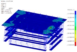
a) WC1 HISSF platform von Mises stress diagram
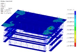
b) WC2 HISSF platform von Mises stress diagram
c) WC3 HISSF platform von Mises stress diagram
Discussion on static analysis results of HISSF platform: The calculation and analysis show that the WC3 working condition of 1.35 Gravity load +1.4 wind load is the most unfavorable working condition. All components of the HISSF platform meet the strength requirements. The maximum Von Mises stress of the radiant beam is 71.1 N/mm2, the maximum Von Mises stress of the Upper main beam of platform is 146 N/mm2, and the maximum Mises stress of the HISSF platform occurs at the climbing rod and jacks, reaching 165 N/mm2. Working condition WC4 is a stiffness-controlled load combination. Calculations show that the maximum vertical downward displacement of the HISSF platform is 5.04 mm. Its value is much smaller than the allowable value of structural displacement determined by the construction requirements l/400 = 29.6 mm, which meets the rigidity requirements.
Table 3Stress value and displacement value of each member under WC3
WC3 | Maximum von Mises stress (N/mm2) | Maximum displacement in direction (mm) | Maximum displacement in direction (mm) | Maximum displacement in direction (mm) |
Radiant beam | 71.1 | 14.5 | 11.9 | 4.9 |
Upper main beam of platform | 146 | 13 | 10.7 | 4.6 |
Upper longitudinal beam of platform | 43.9 | 12.9 | 11.2 | 3.8 |
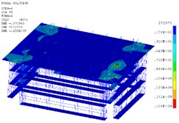
Fig. 5The upper members of HSSIF platform Von Mises stress and Z-direction of displacement
a) The upper members of the WC3 HSSIF platform Von Mises stress diagram
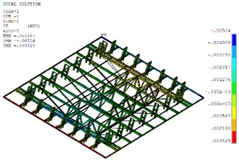
b) The upper members of the WC4 HSSIF platform -direction of displacement
4.2. Analysis of dynamic characteristics of HISSF platform
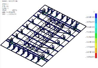
Modal analysis can analyze the vibration characteristics of the structural system and obtain the natural frequency and vibration mode of the structure. ANSYS provides seven methods for extracting modes. Considering the size of the structure model and the number of orders to be extracted, this study chooses the Subspace method in ANSYS to extract the modes. The first five modes of the extracted structure are shown in Table 4, and the first three-orders modal diagram of the structure are shown in Fig. 6.
Table 4Natural frequency
Species | Mode 1 | Mode 2 | Mode 3 | Mode 4 | Mode 5 |
Natural frequency (Hz) | 2.913 | 3.400 | 8.012 | 10.507 | 10.708 |
Discussion on modal analysis results of HISSF platform: The frequency of the first-order mode is 2.913 Hz, the HISSF platform vibrates along the long axis y direction, and the climbing rod bend along the long axis direction, while the radiant beam and the Upper main beam of the HISSF platform are not bend. The frequency of the second mode is 3.400 Hz, the HISSF platform vibrates in the plane. The lower part of the HISSF platform hanging scaffolding is overlapped with the chimney tube wall structure, so that when the HISSF platform vibrates in the plane, the platform hanging scaffolding is twisted. The frequency of the third-order mode is 8.012 Hz, and the HISSF platform is twisted around the axis.
5. Conclusions
In this paper, static analysis and modal analysis of the HISSF platform are carried out through ANSYS platform. We can draw the following conclusions.
1) Under the most unfavorable working condition WC3, the von mises stress value of each member of the platform is small, the maximum is 146 N/mm2, which meets the strength requirement. The displacement value of each member of the platform is not large under the WC4. The maximum deflection of the platform is 5.04 mm, which meets the rigidity requirements.
2) Under the combined action of the load, the HISSF platform has a large displacement on the plane. During the construction process, the horizontal structural connection of the support rods should be strengthened.
3) Only two -direction anchors at the lower end of each scaffold are considered in the model. During the modal analysis, the hanging scaffolding above the second-order mode will produce torsion, causing local stress concentration. In actual construction, the horizontal structural connection between the hanging scaffolding and the chimney wall should be strengthened.
References
-
Y. Y. Hu Lecture eight: formwork engineering construction for super tall building (Part One). Building Construction, Vol. 31, Issue 4, 2009, p. 300-304, (in Chinese).
-
Peng X. C., Meng C. L., Zhang X. Y., et al. Sliding Formwork Engineering Technical Standards: GB/T 50113-2019. Construction Industry Press, Bei Jing, China, 2019, (in Chinese).
-
Brockmann T., Kreiner A., Lohaus L. Further development of the sliding construction method. Concrete and Reinforced Concrete Construction, Vol. 103, Issue 7, 2010, p. 498-506, (in German).
-
Mohammadi G. E., Siamak T. Predicting the climbing rate of slip formwork systems using linear biogeography-based programming. Applied Soft Computing, Vol. 70, 2018, p. 263-278.
-
Pekmezci B. Y., Voigt T., Wang K. Low compaction energy concrete for improved slipform casting of concrete pavements. ACI Structural Journal, Vol. 104, Issue 3, 2007, p. 251-258.
-
Larrard F. D., Roussel N. Flow simulation of fresh concrete under a slipform machine. Road Materials and Pavement Design, Vol. 12, Issue 3, 2011, p. 547-566.
-
Lachemi M., Elimov R. Numerical modeling of slipforming operations. Computers and Concrete, Vol. 4, Issue 1, 2007, p. 33-47.
-
Abdel Khalek H.-A., Khoury S. S., Aziz R. F. Simulation analysis for schedule and performance evaluation of slip forming operations. American Journal of Civil Engineering, Vol. 3, Issue 1, 2015, p. 9-25.
-
Wang X. M., Li Y. Q., Xu H. W. ANSYS Structural Analysis Unit and Application. People’s Communications Press, Bei Jing, China, 2011, (in Chinese).
-
Wang F. Calculation method and engineering application of the bearing capacity of reinforced support rods in hydraulic sliding form. Architectural Knowledge: Academic Journal, Vol. 3, 2013, p. 348-349, (in Chinese).
-
Jin X. Y., Wang J., Wang G. Y., et al. Code for Building Structural Loads: GB 50009-2012. China Construction Industry Press, Bei Jing, China, 2012, (in Chinese).
About this article

This work was financially supported by Fundamental Research Funds for the Central Universities (2020CDJQY-A067) and National Key R&D Program of the Ministry of Science and Technology (2019YFD1101005-4).
