Abstract
Multi-purpose mobile robots with a modular layout have become a hot research topic in recent years. The safe performance of these robot’s operations is relying on the low-level cyber-physical system (CPS). In this paper, the scientific goals underscore the analysis of the computational (cyber) units for low-level real-time fault monitoring. The purpose of these units is to monitor control signals issued by other (cyber) units or sensors and if there is a safety-critical problem, then predefined actions can be triggered. The safety controller was built and tested on the TalTech iseAuto platform. Based on the results, a new multi-layer universal safety system was developed. In the first layer, all signals and messages are checked to be in a suitable range or order. The second layer detects if an accident is happening using crash sensors. The third layer includes remote control switches support. If a failure or malfunction occurs, the emergency action plan is executed to stop the vehicle safely.
1. Introduction
Automotive security has become more challenging with the increase of sophisticated modern technologies nowadays. Also, autonomous vehicles rely on the absolute certainty that electronic systems will function as intended, without malfunction. If hazardous events happen, then preventive or corrective measures are executed.
Tallinn University of Technology (TalTech) developed a low-level control architecture of the cyber-physical system (CPS) first for a self-driving last-mile bus called iseAuto [1], [2]. Based on the same architecture, a new small-scale logistic robot BoxBot [3] has been developed to move goods in industrial environments.
A separate safety controller and its software have been developed for iseAuto by the Estonian branch of ABB. The safety controller was platform-specific and not modular at all. Several other security controllers and solutions exist, but the analyzed solutions are specific and not compatible with our expectations. The task of the observed solutions was either to monitor signals, detect accidents and call for help, or be a radio-controlled emergency stop system. In this case, a controller would be needed, where all this is integrated into a single system.
The research’s novelty is to lay the foundation of a modular solution suitable for using iseAuto and mobile industrial robot BoxBot. The paper’s outline analyzes the existing safety controller and proposes new ideas to build the new computational (cyber) units based real-time fault monitoring system.
2. State-of-art
Traditional car security systems rely mainly on driver assistance technologies, vehicle theft prevention, and passive protection if a crash occurs. Functional safety features needed by mobile robots with a modular layout are different because there is no human driver. The speed usually does not exceed 20 km/h for a legislative reason. Similar safety system - a high-performance safety controller is used for excavators [4]. The safety unit has two microcontrollers, one for standard function and the other for real-time diagnosis via the cross-communication interface to fulfill safety requirements up to PL e and SIL3. It includes various interface types like digital input, digital output, analog input, and PWM output. Interface types are similar to the iseAuto safety controller, developed by the ABB. The embedded software is divided into two parts: safety-related part and non-safety-related part. These two parts are isolated to make sure they will not affect each other.
An experimental automotive safety system [5] indicates a list of faults on the screen. The system has a master and slave module connected through a communication interface. The master module is located inside the car cab and has an LCD screen to display sensor information. Also, it has a gas leakage detection with protection and temperature monitoring function. The slave module has an automatic front headlight adjustment subsystem and a short circuit fault indication function. Two modules, master and slave, are communicating through a Control Area Network (CAN) bus. By developing this further, several specific security modules can be built and connected.
Robert Bosch first invented the CAN bus in 1983. Vikash Kumar Singh designed the 'CAN' protocol in automobiles using an advanced embedded system [6].
Two studies describe a vehicle collision detection and reporting system. One of them uses an MPU6050 motion-tracking device that contains a MEMS accelerometer and MEMS gyro in a single chip [7]. Another work based on a cheap piezoelectric element meant for use as a sound generator. When vibration or mechanical stressor is occurring, then the piezoelectric element emits an electric charge. It exploits the piezoelectric property of the piezoelectric crystals [8].
A research paper proposes a wireless emergency button solution that connects robots with many remote-control devices used by many different users. It is based on an XBee radio module, and relays were used to switch robot power. Even if one of the pushbutton switches fails, the implemented system would detect it and stop the robot. The working radius is more remarkable than other emergency systems, about 25 m [9].
3. Technical solution
3.1. Safety system construction and overview
The initial safety system was implemented on iseAuto, developed in cooperation with an ABB Estonia development team. iseAuto autonomy is achieved by running Autoware in a PC on top of a Robot Operating System (ROS) that communicates with the controllers over dedicated Ethernet to minimize delays. Mission-critical controllers are divided into three layers - master controller, slave controllers, and real actuators and sensors. The master controller’s main task is to forward information from and to the PC with the minimum delay. Mission-critical drive controllers manage a gearbox, brakes, hand brakes, a steering wheel, and a gas pedal [10].
The first safety controller implementation is divided into three separate controllers, as shown in Fig. 1. The first controller which was built is a safety controller to monitor CAN bus and different signals. It is connected directly to the mission-critical drive controller to monitor it, and if there is a fault, then safety relays will be activated.
Safety relays are inside a separate module and directly switched the brake actuators and platform ignition signals in the right order. For this reason, timing circuits were included. Also, the vehicle emergency stop switches located inside the vehicle are connected to the relay module.
If the development continued, then it was necessary to operate the self-driving vehicle without a safety operator. In this case, the operators were close to the vehicle and there was a need to develop a wireless safety button. A solution based on the LoRa network proved successful in testing, and an extra LoRa based remote safety switch controller was included.
The next development was that the remote-control center concept was introduced. The remote-control center could be located anywhere in the world. For this reason, Ethernet-based safety modules were included. The vehicle module uses a car network and 5G modem to connect to the internet. The button side uses Wi-Fi or Ethernet connection. Both extra controllers directly control the safety relay box.
3.2. Safety controller
The safety controller based on drive controller hardware is shown in Fig. 2. Its General-Purpose Inputs and Output (GPIO) pins are connected to the drive controller’s analog and digital pins for real-time signal analysis to determine whether the expected signal levels are in the appropriate range. If the signal is out of range, then it automatically activates the brake signal, which immediately stops the vehicle.
Fig. 1The architecture of the TalTech iseAuto safety system
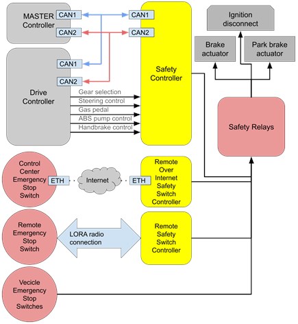
Fig. 2The custom-built safety controller

A separate safety/measurement board provides a single point for getting the actual measured control signal values issued by the drive controller. Measurement results are published into CAN bus, and the system can retrieve measurement results from there. Measurements are taken from the control board output before auxiliary control electronics. Main functions of developed safety controller:
– Controlling Relay/Break supply module for making an emergency shutdown based on a command from the master controller. Engaging emergency brake on master controller request.
– Measuring gas, steering, brake, and gear selection signals. Detecting any abnormalities in these signals and performing an emergency shutdown when anomalies occur.
– Measuring the handbrake the actual state (is it applied or not) and forwarding this information to the master controller over CAN bus.
– Sending measurement results of gas, steering, brake, and gear selection over CAN bus to the master controller.
The safety controller should react to any abnormal conditions, listed in Table 1 or an emergency shutdown command from the master without delay. When abnormal signal values are detected, the safety controller sends a signal to the safety relay module to activate the emergency shutdown.
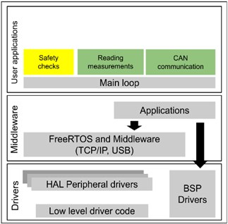
The safety controller is based on the STM32F407VGT6 microcontroller and is physically connected with different driving-related signals on the drive controller. Various safety checks were executed inside the user application space alongside CAN bus communication and measurement routines, as shown in Fig. 3. For automatic testing, the simulation environment was set up to emulate a vehicle with a PC so that the safety controller could be tested without the necessity of a real vehicle.
Table 1Abnormal conditions detection
Signal | Condition |
Gas | The gas pedal signal consists of two voltage signals. When gas „position” is controlled, the values of both sub and main have to change simultaneously. Also, Main/Sub should always have a certain ratio. So Main/Sub ~= 0,5 The safety controller could check the ratio and that both signals change correctly. |
Steering | Steering control is done with a single 50 Hz PWM signal. Pulse width should be between 1 – 2 ms. If pulse width drops below 1ms or goes over 2ms safety controller could flag this as a problem and apply emergency braking. |
Handbrake | A 5 kHz signal is used for controlling the handbrake. The safety controller could measure the frequency of the signal and if it goes out of range, drops significantly below, or goes above 5 kHz, a safety controller could trigger an emergency shutdown. Also, the condition when the drive controller is trying to apply and release the brake at the same time could be flagged as a problem. |
Gears | Check that the gear selection is made according to specified order P→R→N→D. Trying to engage multiple gears simultaneously would also be a failure. |
Fig. 3The software architecture of the safety controller
3.3. Remote over internet safety switch controller
The remote over internet safety switch system consists of two modules. The vehicle-side module has a power connection, Ethernet interface, and safety relay output. The remote-control center module an Ethernet and power connector on the side of the module. The remote over internet safety switch modules are based on the ESP32 controller. This controller has ESP32-WROOM generic Wi-Fi+BT+BLE MCU that targets a wide variety of applications [11]. Also, it includes the Ethernet PHY with connector and CAN bus interface. For data exchange with the server, the MQTT protocol is used. The IoT framework has the following functionality:
– Operating mode to set network/server parameters using a separate app.
– Automatic Ethernet / Wi-Fi network / MQTT server connection management.
– Sending/receiving messages from the MQTT server.
– Remote management to save or change parameters stored on the device memory.
– Software upgrades over a network connection.
– Status monitoring and periodic statistics.
3.4. A remote safety switch controller
The remote safety switch system contains two modules again. The vehicle-side module has a power connection and a safety relay output. The remote hand-held switch module has a safety switch, and an OLED screen to display status information. Both modules consist of a TTGO LoRa32 ESP32 development board with a built-in SX1276 LoRa chip. LoRa based solution is chosen because it allows long-range communication, high immunity to interference, and minimal power consumption. A packet with button status info is sent over the LoRa connection. If some packet goes missing, then if the connection resumes, the relay status is updated immediately.
4. Experiments
In this section, we follow different levels of testing presented in [12] that is required to check and verify the safety system. It is a major challenge to test and check the validity of both physical and cyber elements of such a complex CPS. The process includes evaluation of hardware and software, computer and communication testing, integration validation, and examination of the entire system. In the following, we present our experiments in the different levels of testing.
Hardware and software testing: the functionality of all hardware components of our safety system, including safety controller, relays, and remotes, were individually tested based on the system requirements. In this step, hardware and especially their I/O interfaces (ports) were examined and monitored to verify their operations. After 2 times testing and finding some faults in the design and the performance, we finally passed all the test criteria in the third test. Several modifications were made during the tests to the initial hardware schematic related to the noise removal issues. Also, software and computation testing were performed first using simulations and then through implementing on the hardware to check the validity and performance of the control algorithms. overall, the software part was optimized during the whole experiments period to ensure a high safety factor.
Network testing: CAN, Ethernet, and 5G internet networks are the main connection protocol between our safety system components. Each of these protocols was tested individually at least 3 times by sending predefined messages through them to the corresponding unit to ensure the correct functionality of the different ports. No error was observed during the tests.
Integration testing: this kind of examination is a part of software testing with combining individual modules in a group. Thus far, all units were tested solely, but the integration of the modules before putting them in the whole system enables us to find possible errors easily. In this case, checking the remote, the safety controller, and relays operation are carried out by integration testing in three consecutive tests. No malfunction was observed in these units.
System testing: hardware or software system testing is eventually connected to testing a fully integrated system as all units are integrated into a system to satisfy the overall system requirements. In the final step, all units, including the safety controller, remotes, and relays, were mounted on the platform (AV shuttle iseAuto) to have a fully integrated system for examination. 18 experiments were carried out in two weeks and in different scenarios. Examinations were categorized into two main groups. The first was testing the system under the normal operation, and the second was under the false data injection.
In the normal mode, the vehicle operates regularly, and the safety controller reacts based on its monitoring and safety functions. Eight comprehensive test scenarios were defined, and all safety features were tested, such as all the emergency buttons operations, remote controlling practicality, and monitoring of the signals. Some additional monitoring features were added during these tests, like crash sensors to automatically stop the vehicle immediately in case of any crash and a backup battery voltage monitoring to avoid losing vital power source that runs the safety features. However, the test results were satisfactory and acceptable. For covering unknown situations in the testing process, false data injection is used to simulate and put the safety system under heavy tests. In this method, during 10 test scenarios, different false data sets were sent as an input to the different units on the vehicle controller to see the safety controller reaction. This method also enables us to investigate the system reaction in cyber-attacks that primarily target the vehicle controller. Our proposed safety system was successfully passed through these examinations, and only it failed in one of the subtests that led to some minor modifications that were performed in the software section for keeping the safety command in the right order.
5. Conclusions
In this paper, the scientific goals underscore the analysis of the computational (cyber) units for the low-level real-time fault monitoring system. The safety controller was built previously and tested on the TalTech iseAuto platform. Later it was necessary to add a LoRa-based remote control switch meant to be used near the vehicle. Also, later over the internet safety button was added. The results were analyzed, and a new multi-layer universal safety system was proposed. First layer checks if a specific signal or message is in a suitable range or order. The second layer detects if an accident is happening using crash sensors. The third layer includes remote control switches support. If a fault or event is happening, the emergency action plan is executed to safely stop the vehicle. Overall, the whole safety unit is evaluated and developed in different levels under at least 30 comprehensive tests.
References
-
R. Sell, M. Leier, A. Rassolkin, and J.-P. Ernits, “Self-driving car ISEAUTO for research and education,” in 2018 19th International Conference on Research and Education in Mechatronics (REM), pp. 111–116, Jun. 2018, https://doi.org/10.1109/rem.2018.8421793
-
R. Wang, R. Sell, A. Rassolkin, T. Otto, and E. Malayjerdi, “Intelligent functions development on autonomous electric vehicle platform,” Journal of Machine Engineering, Vol. 20, No. 2, pp. 114–125, Jun. 2020, https://doi.org/10.36897/jme/117787
-
H. Pikner, R. Sell, K. Karjust, E. Malayjerdi, and T. Velsker, “Cyber-physical control system for autonomous logistic robot,” in 2021 IEEE 19th International Power Electronics and Motion Control Conference (PEMC), Apr. 2021, https://doi.org/10.1109/pemc48073.2021.9432526
-
K. An, “Development of high-performance safety controller for excavator,” IOP Conference Series: Materials Science and Engineering, Vol. 922, No. 1, p. 012003, Oct. 2020, https://doi.org/10.1088/1757-899x/922/1/012003
-
K. Kalaiyarasu and C. Karthikeyan, “Design of an automotive safety system using controller area network,” in 2015 International Conference on Robotics, Automation, Control and Embedded Systems (RACE), Feb. 2015, https://doi.org/10.1109/race.2015.7097263
-
V. Singh, K. Archana, and Himayat Sagar, “Implementation of ’CAN’ protocol in automobiles using advance embedded system,” International Journal of Engineering Trends and Technology (IJETT), Vol. 4, No. 10, pp. 4422–4427, 2013.
-
K. G. Gurmanpreet and L. Meenu, “Vehicle collision detection and reporting,” International Journal of Innovative Research in Technology, Vol. 5, No. 4, pp. 220–222, 2018.
-
D. H. Kumar, S. Srivastava, S. Kumar, and S. Gupta, “Accident detection and reporting system using GPS and GSM module,” International Journal of Emerging Technologies and Innovative Research, Vol. 2, No. 6, pp. 1433–1436, 2015.
-
D. García, R. Barber, and M. A. Salichs, “Design and development of a wireless emergency start and stop system for robots,” in 11th International Conference on Informatics in Control, Automation and Robotics, Vol. 2, p. 2014, 2014, https://doi.org/10.5220/0004926602230230
-
A. Rassolkin, L. Gevorkov, T. Vaimann, A. Kallaste, and R. Sell, “Calculation of the traction effort of ISEAUTO self-driving vehicle,” in 2018 25th International Workshop on Electric Drives: Optimization in Control of Electric Drives (IWED), pp. 1–5, Jan. 2018, https://doi.org/10.1109/iwed.2018.8321397
-
A. Maier, A. Sharp, and Y. Vagapov, “Comparative analysis and practical implementation of the ESP32 microcontroller module for the internet of things,” in 2017 Internet Technologies and Applications (ITA), p. 32, Sep. 2017, https://doi.org/10.1109/itecha.2017.8101926
-
S. Abbaspour Asadollah, R. Inam, and H. Hansson, “A survey on testing for cyber physical system,” in Testing Software and Systems, Cham: Springer International Publishing, 2015, pp. 194–207, https://doi.org/10.1007/978-3-319-25945-1_12
About this article

The research is supported by the EC H2020 project Finest Twins (Grant No. 856602).
