Abstract
In this article, we have reviewed the available positioning, localization and navigation techniques for mobile robots. Different localization techniques based on diverse technologies are compared with one another, along with diverse algorithms and techniques for analyzing this information. The article highlights algorithms based on odometry, triangulation, visual analysis, and marker detection. The analysis included global, local, and personal location. One acquires knowledge on which method is suitable for indoor use and which for outdoor use, as well as the appropriate environmental conditions for each. The accuracy of the individual methods was compared with that of integrated systems consisting of several methods. For practical knowledge, it is possible to determine whether a particular method is cost-effective for a particular solution and to compare the expenses involved.
1. Introduction
Localization can be defined as the process of tracking and controlling the movement of objects from one location to another. The subject is extensive and draws upon diverse scientific disciplines, including but not limited to mathematics, computer science, electronics, mechanics, and robotics. Furthermore, sometimes referred to as navigation, it is possible to categorize location into four primary categories, namely land, sea, air, and space. The term can also be used when determining one’s own location.
One of the key features of a location system is its scale, and the physical size of a device’s localization is determined by the required navigation precision. The scale can vary considerably depending on the needs. The first approximation of scale is the devices dimensions, as any mobile location device must be able to determine its position with an accuracy at least close to its size. In order to organize the requirements for location systems, scales are classified into three distinct categories: global, local, and personal. Global-scale navigation is the ability to determine one's position in a global frame of reference, such as a map, and to travel between different locations. Local-scale localization entails determining the position relative to other objects, which can be fixed or moving. Personal navigation involves finding a position relative to other elements that together form a complete system.
To navigate in AGV (Automated Guided Vehicles) space, it is necessary to utilize physical route marking, typically by magnetic or color line. In contrast AMR (Autonomous Mobile Robots) utilizes natural navigation, which maps the space based on 2D or 3D sensors and generates a virtual map on which the robot moves. Within natural navigation, a distinction is made between SLAM (Simultaneous Localization and Mapping), LiDAR (Light Detection and Ranging), or LMS (Laser Mapping System) methods.
Another fundamental concept associated with localization is the reference system, which can be either relative or absolute. Absolute localization refers to determination of a location in relation to a fixed point in space, based on the scale of the location. Relative localization involves determining a position relative to objects in the environment of a mobile device.
In this article the mainstream positioning methods and related positioning technologies are highlighted. A comparative analysis is made based on positioning accuracy, cost, and advantages and disadvantages.
2. The classification and selection of localization method
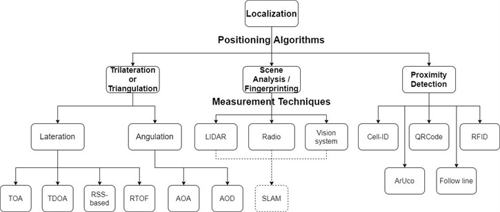
There are a lot of algorithms and measurement techniques for localization (Fig. 1), and it is possible to distinguish a subset of those that rely on the reproduction of a pre-programmed route, such as where a map that has been pre-designed and uploaded, or a route that is mapped by markers or lines [1-3]. A distinction can be drawn between those that rely on reference points, such as magnetic lines [4], RFID [5, 6], QRCode [7, 8], and others, and those that employ image recognition [9] and artificial intelligence techniques [10-13]. Another group uses sound (ultrasonic) waves [14, 15] or electromagnetic waves, such as laser [16-18], infrared [19] technologies, and radio waves [20-22], such as Bluetooth [23] or UWB [24, 25] technologies.
In the process of positioning by scene analysis, initial data collection involves identifying the characteristics or fingerprints of an environment. Subsequently, the location of an object is determined by combining the measurements taken online with those performed a priori during a calibration phase. The transmitted signal power is commonly used as a fingerprint in scene analysis.
In this context, it is also possible to distinguish between personal, local, or global navigation. Based on the fact that emitters are mounted on the mobile robot, it is possible to determine the direction of a route based on information from these sensors. The robot can also determine its position by examining the signal intensity [26]. Local localization can be achieved when appropriate sensors/cameras are deployed in a building, which transmit information to a central unit [27]. This allows robots to be managed centrally. Global localization frequently relies on the utilization of GPS technology [28, 29], thereby enabling the possibility of locating across the entire globe.
Odometry, a branch of metrology that focuses on distance measurement, can be employed for pose estimation. By utilizing motion sensors, it is possible to determine the change in position of an object relative to a previous position over time. Frequently used sensors are inertial sensors such as accelerometers, gyroscopes, or magnetometers [30]. Movement can be interpreted in up to nine axes of freedom. The most commonly employed IMU sensors [31] are MEMS (micro electromechanical system) sensors, as they have a small footprint and are relatively cheap. Another technique used to estimate position is wheel odometry, which uses encoders to count the number of revolutions of the wheels that are in contact with the ground [32]. In this method, it is important to select suitable filters. One can distinguish between particle filters [33] and the well-known Kalman filter [34, 35]. Furthermore, it is worth mentioning the errors that can result, for example, from wheel slippage [16].
Visual odometry is the process used to determine the position and orientation of a robot by analyzing the associated camera images. It is important to note that visual odometry is focused on local consistency and attempts to incrementally estimate the path of the camera/robot pose after pose, and possibly perform local optimization. In contrast, SLAM aims to obtain a globally consistent estimate of the camera/robot trajectory and map. Global consistency is achieved by knowing that a previously mapped area has been checked again (loop closure) and by using this information to reduce the drift in the estimates [36]. Among all kinds of SLAM (LiDAR-based SLAM, Radio-based SLAM), visual SLAM (VSLAM) is the key academic research due to its advantages of low price, easy installation, and simple algorithm model [37-39].
Each of the localization methods is subject to a greater or lesser error (Table 1). Before selecting the appropriate technology, it is imperative to inquire about the desired accuracy and the possessed capabilities. The most effective approach appears to be to employ multiple methods to localize a single object, thereby minimizing the error rate. However, due to the complexity of the algorithms and the requirement for additional computing power, the system becomes more complex, making it even more challenging to implement in small mobile robots, resulting in a higher cost. Visual methods with artificial intelligence algorithms have the highest accuracy, but are therefore among the most expensive methods. The cheapest methods to implement seem to be odometry-based methods using QRCode/ArUco or follow line. A moderate price applies to technologies based on laser rangefinders, RFID tags, GNSS, radio waves, or ultrasound. Among the most expensive methods is image recognition or LiDAR. It is worth noting that the final price is also composed of the algorithms used to calculate the position.
Table 1A review of literature on mobile robot positioning technology
Positioning technology | Algorithm or technique | Accuracy | Article |
Laser | Pose tracking | Minimal error: 5.3 cm on 4 m/s | [16] |
Odometry and QRCode | Filter H ∞ (EHF) | Mean error: 30 mm and 0.5° | [7] |
RFID (RSSI) | Particle Filter | Minimal error: 5.9 cm and 2.1° | [5] |
Laser | Particle Filter | Minimal error: <1% | [33] |
RTK-GPS | Extended Kalman Filter | Minimal error: 0.103 m and 3.32° | [17] |
Odometry | CORDIC | Mean error: ~0.6° | [32] |
WSN (radio waves) and IMU (odometry) | Filter H ∞ | Minimal error: 0.1313 m | [20] |
Vision system and LED markers | Extended Kalman Filter | Minimal error: 0.06 m/s | [27] |
Vision system and natural landmarks | 3D vision | Minimal error: 1.8 cm and 0.1° | [10] |
Follow line | Lyapunov approach | Mean error: 5.25 cm | [4] |
Vision system | Deep learning, PV-RCNN | Mean error: 0.5 mm and 0.3° | [11] |
Ultrasonic | DTOA | Mean error: 3.5 cm | [14] |
Ultrasonic | Extended Kalman Filter, UHL | Mean error: 0.07 m and 1.98° | [15] |
Radio waves, RF | Extended Kalman Filter, particle filter | Minimal error: 0.23 m | [21] |
LiDAR | RGB color information | RMSE: 0.111 m | [45] |
GNSS (GPS) | Adaptive Kalman Filter | Minimal error: 17 mm | [47] |
GNSS (GPS) | Fisheye | Minimal error: 0.05 m | [28] |
Odometry (IMU and Encoder) | Kalman Filter, EKF | Maximal error: 0.5 m | [31] |
Radio waves (Bluetooth RSSI) | WKNN, Kalman Filter | Mean error: 1.91 m | [23] |
(HF)-band RFID | Monte-Carlo | Mean error (for 8 HF-band RFID and Combination 100 tags/m2): 4.7 mm (x), 22.8 mm (y), 0.019 rad | [6] |
Ultrasonic and radio waves (UWB) | TDOA | Average dynamic errors: 0.35 m Pozyx and 0.15 m GoT | [24] |
Ultrasound | TDOA | Mean error: 1.57 cm | [42] |
PIR and ultrasonic | Decision Tree, K-Means | Reconstruct direction: 70.7 % | [19] |
Vision and LiDAR | YOLOv7 | Average: 95 % | [46] |
Visual marker, LiDAR, IMU, Encoder | Extended/Untraced/error-state Kalman Filter, particle filter, Lins, Fast-Lio (2) | RMSE relative to ground truth: 0.12 m | [48] |
Follow leader, vision, IMU, GNSS, ArUco markers | Extended Kalman filter | Minimal error: less than 4 cm in all axis | [35] |
Odometry | Extended Kalman filter (EKF) | Mean deviation: 11.3 mm | [18] |
LiDAR and vision | Original | Deviation: 0.4° and 2 cm | [9] |
AGV navigation (QR code) | Improved AMCL particle positioning | Minimal Error: 5.2 cm | [8] |
Radio waves (UWB) | Asymmetric two-way ranging (ADS-TWR) | Maximal Error: 10 cm | [25] |
GPS | [–] | Mean error: 3 cm (RTK DGPS correction mode) | [29] |
Radio waves (WLAN, WSN, UWB), RFID | TDOA, AOA | Average accuracy: 19.1 cm | [26] |
Odometry | Kalman filter | Mean error: 0.4 % | [30] |
Ultrasonic | FMCW | Maximal error: 50 mm | [43] |
UWB, IMU, Odometry, LiDAR | EKF, AMCL | RMSE: 0.04 m | [49] |
Fig. 1The classification of methods for localizing a mobile robot
Another question concerns the conditions and the place where the robot will be operating. For instance, in the heavy industry, the implementation of localization utilizing wireless technologies may prove ineffective due to the numerous errors resulting from interference, such as electromagnetic interference arising from the presence of numerous machines and wireless devices operating nearby, such as gate remotes and WiFi access points. In locations with frequent vibrations with significant amplitudes and different frequencies, a method based on inertial sensors may also be subject to high error, as it may be difficult or impossible to filter the signal from random vibrations. Other important considerations include the environmental conditions in which the robot is to operate. In places where there is a lot of contamination, like a paint shop, it might not be possible to use visual or ultrasound methods. The detector can get damaged quickly, but using special protection measures can make it less likely to happen. The comparison of different technologies to localize a mobile robot, with their advantages and disadvantages, is presented in Table 2.
Table 2The comparison of different technologies to localize a mobile robot.
Positioning technology | Costs | Advantages | Disadvantages | Article |
Laser | Medium | Good accuracy at medium speeds | Use of high-speed data processing and susceptible to contamination | [16], [33] |
Odometry IMU/Encoder | Low | Easy to apply, many degrees of freedom | Errors due to the design of the sensors themselves | [7], [12], [18], [20], [30-32], [35], [48], [49] |
QRCode/ArUco | Low | Quick and simple application, easy to change course - new marker | Susceptible to soiling | [7], [8], [35] |
RFID | Low/ Medium | Route tracking and provision of location information | Covering the entire area with a grid of markers | [5, 6] |
GNSS (GPS) | Medium | Global location determination and simple navigation thanks to extensive maps | Limited range (mainly indoors) | [12], [17], [28, 29], [35], [47] |
Radio waves | Medium | Good accuracy, resistant to harsh environmental conditions | Application of complex data processing algorithms | [20-26], [49] |
Vision system | High | Very high accuracy, can be used virtually anywhere, ambient mapping | Mainly based on artificial intelligence, so very sophisticated image recognition algorithms | [9-12], [27], [41], [46] |
Follow line | Low | Simple to implement, good track record | There must be a continuous reference point (line) | [1-4] |
Ultrasonic | Low/ Medium | Multiple signal processing options, high accuracy at low speeds | Limited operating range, low accuracy at higher speeds | [14, 15], [24], [42], [43] |
LiDAR | Medium/High | Possibility of mapping with good accuracy, fast operation | Poor dirt resistance, complex information processing | [9], [13], [45, 46], [48] |
Other markers | [-] | Easy to find (self) robot, with known marker location | High density of markers needed for decent work | [10], [27], [48] |
3. A review of the selected localization methods
3.1. Following the magnetic or optical line
The methodology is based on the juxtaposition of a displacement path with a suitable detector. Typically, optical lines with high contrast are employed to enhance the clarity and ease of processing of the sensor signal (Fig. 2). It is a common occurrence to utilize multiple sensors to increase accuracy or to augment the capability to track multiple lines. Among optical sensors, we can distinguish those that operate in the visible range (responding to contrast or color) or the infrared range. By adding the ability to track multiple lines at the same time, we can create more complex routes and use the cooperation of multiple robots. Due to the fact that optical detectors are sensitive to dirt, they are used in clean areas with very low dust levels.
Fig. 2The Arduino-based line follower robot [3]
![The Arduino-based line follower robot [3]](https://static-01.extrica.com/articles/23893/23893-img2.jpg)
For many applications, it is difficult to keep dust levels low, and magnetic tapes are used. A Hall sensor is usually used as a detector. This solution is more expensive when constructing extensive routes. However, it exhibits greater resistance to dirt than an optical solution [40].
3.2. Reference tags/points – RFID/QRCode
Markers play a crucial role in localization. Thanks to them, we are able to determine the initial position of the robot. The object, having acquired knowledge of the map of the markers, can, upon becoming lost for various reasons (such as power outage or manual relocation), either return to the previous point or alter the route to a more optimal one.
RFID is a radio-based technology, which possesses a relative degree of dirt resistance compared to QRCode. According to the available information, the two main categories of RFID-based localization methods are reader and tag. The tag density must be increased in order to increase localization accuracy (Fig. 3), however, this also involves more time-consuming information processing [6].
The utilization of QRCode is based on the examination of the information contained within such a tag, such as the approximate global location and the mobile robot’s heading direction . The disadvantage of this application is that an optical system is required to read these tags, which is less resistant to fouling than an RFID receiver. The advantage is that we can implement more information.
Fig. 3The RFID-based localization system for mobile robot [6]
![The RFID-based localization system for mobile robot [6]](https://static-01.extrica.com/articles/23893/23893-img3.jpg)
3.3. Image detection
The method is one of the most advanced, and also one of the most difficult to implement, but when combined with artificial intelligence, it produces very good results. Thanks to continuous image recognition, we are able to react to unpredictable changes in the course, such as the appearance of obstacles or the appearance of new landmarks (e.g. new buildings). It is important to utilize a high-quality camera or cameras in order to accurately determine the distance of more distant features with a high degree of accuracy.
It is noteworthy that it is imperative in this methodology to distinguish between obstacles and target objects in real time (Fig. 4). It is important to utilize a camera that has been calibrated appropriately to ensure that the image does not suffer from distortion. The implementation of artificial intelligence involves learning, for example, a robot following the same target can change its route each time as it chooses a more optimal one [41].
3.4. Ultrasonic system
The primary advantage of ultrasonic signals is their low propagation speed compared to the processing speed of electronic systems. This enables the capture of the propagation delay between known points with high precision. The proposed method can be classified into two distinct categories: the time-of-arrival (TOA) localization technique, wherein the system estimates the propagation delays between a sent and received signal, and the differential time-of-arrival (DTOA) techniques, wherein the system estimates the propagation delays between multiple receivers [42].
Fig. 4Object detection to navigate mobile robots using artificial intelligence used in indoor environments [41]
![Object detection to navigate mobile robots using artificial intelligence used in indoor environments [41]](https://static-01.extrica.com/articles/23893/23893-img4.jpg)
This technique is employed indoors, as the sound (ultrasonic) wave must be reflected, thereby revealing the relative position information (Fig. 5).
Fig. 5The principle of operation of an ultrasonic system on an unmanned ground vehicle (UGV) [43]
![The principle of operation of an ultrasonic system on an unmanned ground vehicle (UGV) [43]](https://static-01.extrica.com/articles/23893/23893-img5.jpg)
3.5. Radio waves
There exist numerous variations of this method, including those based on Bluetooth, WiFi, ultra-wideband (UWB), and GSM. Furthermore, radio waves can be utilized in a manner that, similar to ultrasound, the propagation time between the transmitter and the receiver can be measured [20]. Examples include the use of the triangulation method (Fig. 6) and the use of BTS base stations [44]. Being within range of several such stations, it is possible to determine the position of an object with a high degree of accuracy.
Alternatively, one solution may be to use wave fading in a medium with known attenuation [21], such as a steel pipe. Knowing the attenuation coefficient for a specific frequency may allow one to estimate the distance between receiver and transmitter with some approximation. Furthermore, by utilizing a greater number of receivers, reliability and resolution can be increased.
Fig. 6A method based on radio waves from BTS stations [44]
![A method based on radio waves from BTS stations [44]](https://static-01.extrica.com/articles/23893/23893-img6.jpg)
3.6. Laser method
The laser method is mainly based on the use of laser rangefinders to measure distances (Fig. 7). The operating principle is similar to that of ultrasonic sensors, but with greater accuracy. Distance information from laser sensors can be obtained by measuring the phase shift of the electromagnetic wave sent out and returning or by measuring the time taken for the pulse to travel from the transmitter to the object and from the object to the receiver. As a result of the fact that the velocity of wave propagation is significantly higher than that of sound waves, it is imperative to utilize systems with very high operating frequencies.
Fig. 7The principles of the LiDAR method [46]
![The principles of the LiDAR method [46]](https://static-01.extrica.com/articles/23893/23893-img7.jpg)
The relative location can determined with this method. A distinction can be made with the LiDAR method [45], whose operational principle is based on the combination of a laser and a telescope. The laser emits very short and precise measured strong pulses of light of a specific wavelength and in a specific direction. This light undergoes scattering along its path, which is observed with a telescope, followed by recording with a sensitive detector and analyzed by a computer.
3.7. GPS
Typically, global localization is based on the utilization of the Global Navigation Satellite System (GNSS), commonly known as the Global Positioning System (GPS). However, this system has many limitations, due to its dependence on satellite signals (Fig. 8). Localization cannot be performed in areas with poor signal reception (e.g. tunnels, underground car parks). Furthermore, the standalone GPS system exhibits limited precision. correction signals, such as differential GPS (DGPS) or real-time GPS (RTK-GPS), are required to achieve precise localization. Using different filtering, location reliability and accuracy can be increased. The conventional Kalman filter is incapable of providing a precise estimation of the robot's turning points, as the results obtained from sudden changes in the robot's position are average. Nonetheless, the implementation of an adaptive version of this filter can yield satisfactory outcomes [47].
Fig. 8The influence of the environment on the satellite signal [28]
![The influence of the environment on the satellite signal [28]](https://static-01.extrica.com/articles/23893/23893-img8.jpg)
3.8. Odometry-based methods
The most common solution is to combine IMU sensors with motorized encoders of mobile robots (Fig. 9). The direct integration of acceleration measurements from inertial sensors to obtain position information is problematic due to the presence of deviations and signal noise. The use of encoders alone is also problematic and can generate large errors in the case of slippage. Inertial sensors are capable of measuring accelerations in various axes, orientation, angular velocities, and other gravitational forces. It is possible to distinguish between accelerometers, gyroscopes, and magnetometers. At present, the most prevalent sensors are MEMS (micro-electromechanical systems) as they are capable of incorporating the three aforementioned types of inertial sensors into a single housing. This enables us to obtain measurements with multiple degrees of freedom.
Through mathematical transformations, we can obtain information about the mobile robot position. This is generally a relative position. However, when utilized in combination with technologies such as GPS, it is possible to determine the absolute position with a high degree of accuracy.
Fig. 9The four-wheeled mobile robot with complex localization (including IMU and encoder) [48]
![The four-wheeled mobile robot with complex localization (including IMU and encoder) [48]](https://static-01.extrica.com/articles/23893/23893-img9.jpg)
3.9. Systems integrated from several methods
By utilizing simultaneous localization and mapping, mobile robots are capable of performing automated navigation tasks in unfamiliar indoor environments. Using systems integrated from several localization methods, high accuracy is achieved. Fig. 10 and Fig. 11 show the localization process into two stages – initial estimation (including sensor data collection and position estimation) and accurate, with mapping of the robot often occurring in the second stage. By dividing it in this manner, it is possible to attain enhanced reliability as the robot can continue to operate despite any damage to any components of the localization system, albeit with reduced localization accuracy.
Fig. 10Visual marker-aided LiDAR/IMU/Encoder integrated odometry [48]
![Visual marker-aided LiDAR/IMU/Encoder integrated odometry [48]](https://static-01.extrica.com/articles/23893/23893-img10.jpg)
Fig. 11Integrated positioning frame diagram based on UWB/IMU/ODOM/LiDAR [49]
![Integrated positioning frame diagram based on UWB/IMU/ODOM/LiDAR [49]](https://static-01.extrica.com/articles/23893/23893-img11.jpg)
4. Summary
The paper presents the most commonly employed techniques for locating mobile robots. Each approach is founded on distinct physical phenomena. There is no one perfect method for localization. To attain optimal outcomes from robot localization, it is imperative to employ a variety of techniques. Also important to note that obtaining accurate measurements directly from the sensors does not yet prove accuracy. The filtering and processing of the data becomes an important element. Therefore, it is worth considering solutions holistically, not only because of the use of the sensors themselves, but also because of the relevant algorithms and hardware processing the information.
The selection of appropriate methods ought to be based on the operational assumptions of a mobile robot. Other methods will be better suited for robots used in industry, where the route is repeated, and others where robots will explore places (e.g. space rovers). It is also important to consider the environment in which such robots will operate, whether outdoors or indoors. It should also depend on environmental conditions. The objects in the close and distant surroundings of the robots are worth noting and trying to predict whether the condition will change in the near future. When using methods related to optics or ultrasound, it is important to ensure of the cleanliness of the detectors. It is important to consider whether robot navigation should be managed centrally or individually. For example, there are many disadvantages related to the loss of connection between the robot and the control panel. The second solution can result in collisions between robots, especially when there is a high density of through robots, for example, an incorrect map. Both solutions can, of course, have some disadvantages, but each case should be analyzed individually.
References
-
J. Goncalves, V. H. Pinto, and P. Costa, “A line follower educational mobile robot performance robustness increase using a competition as benchmark,” in 2019 6th International Conference on Control, Decision and Information Technologies (CoDIT), pp. 934–939, Apr. 2019, https://doi.org/10.1109/codit.2019.8820556
-
A. Latif, H. A. Widodo, R. Rahim, and K. Kunal, “Implementation of line follower robot based microcontroller ATMega32A,” Journal of Robotics and Control (JRC), Vol. 1, No. 3, pp. 70–74, Jan. 2020, https://doi.org/10.18196/jrc.1316
-
H. Li, M. Barão, L. Rato, and S. Wen, “HMM-based dynamic mapping with gaussian random fields,” Electronics, Vol. 11, No. 5, p. 722, Feb. 2022, https://doi.org/10.3390/electronics11050722
-
A. D. Asham, “Mathematical analysis of a line-follower robot, a stable controller design using lyapunov approach, and experimental tests,” International Journal of Dynamics and Control, Vol. 11, No. 1, pp. 385–395, Jun. 2022, https://doi.org/10.1007/s40435-022-00973-x
-
B. Tao, H. Wu, Z. Gong, Z. Yin, and H. Ding, “An RFID-based mobile robot localization method combining phase difference and readability,” IEEE Transactions on Automation Science and Engineering, Vol. 18, No. 3, pp. 1406–1416, Jul. 2021, https://doi.org/10.1109/tase.2020.3006724
-
J. Mi and Y. Takahashi, “Design of an HF-band RFID system with multiple readers and passive tags for indoor mobile robot self-localization,” Sensors, Vol. 16, No. 8, p. 1200, Jul. 2016, https://doi.org/10.3390/s16081200
-
P. Nazemzadeh, D. Fontanelli, D. Macii, and L. Palopoli, “Indoor localization of mobile robots through QR code detection and dead reckoning data fusion,” IEEE/ASME Transactions on Mechatronics, Vol. 22, No. 6, pp. 2588–2599, Dec. 2017, https://doi.org/10.1109/tmech.2017.2762598
-
B. Zhang, S. Li, J. Qiu, G. You, and L. Qu, “Application and research on improved adaptive monte carlo localization algorithm for automatic guided vehicle fusion with QR code navigation,” Applied Sciences, Vol. 13, No. 21, p. 11913, Oct. 2023, https://doi.org/10.3390/app132111913
-
C. Han, W. Wu, X. Luo, and J. Li, “Visual navigation and obstacle avoidance control for agricultural robots via LiDAR and camera,” Remote Sensing, Vol. 15, No. 22, p. 5402, Nov. 2023, https://doi.org/10.3390/rs15225402
-
E. Royer, M. Lhuillier, M. Dhome, and J.-M. Lavest, “Monocular vision for mobile robot localization and autonomous navigation,” International Journal of Computer Vision, Vol. 74, No. 3, pp. 237–260, Jul. 2007, https://doi.org/10.1007/s11263-006-0023-y
-
Z. Zhou, L. Li, A. Fürsterling, H. J. Durocher, J. Mouridsen, and X. Zhang, “Learning-based object detection and localization for a mobile robot manipulator in SME production,” Robotics and Computer-Integrated Manufacturing, Vol. 73, p. 102229, Feb. 2022, https://doi.org/10.1016/j.rcim.2021.102229
-
C. D. de Sousa Bezerra, F. H. Teles Vieira, and D. P. Queiroz Carneiro, “Autonomous robotic navigation approach using deep q-network late fusion and people detection-based collision avoidance,” Applied Sciences, Vol. 13, No. 22, p. 12350, Nov. 2023, https://doi.org/10.3390/app132212350
-
Y. Dai, S. Yang, and K. Lee, “Sensing and navigation for multiple mobile robots based on deep q-network,” Remote Sensing, Vol. 15, No. 19, p. 4757, Sep. 2023, https://doi.org/10.3390/rs15194757
-
S. Elvira, A. Castro, and J. Garrido, “ALO: An ultrasound system for localization and orientation based on angles,” Microelectronics Journal, Vol. 44, No. 10, pp. 959–967, Oct. 2013, https://doi.org/10.1016/j.mejo.2013.01.001
-
S. J. Kim and B. K. Kim, “Dynamic ultrasonic hybrid localization system for indoor mobile robots,” IEEE Transactions on Industrial Electronics, Vol. 60, No. 10, pp. 4562–4573, Oct. 2013, https://doi.org/10.1109/tie.2012.2216235
-
Kai Lingemann, H. Surmann, A. Nuchter, and J. Hertzberg, “Indoor and outdoor localization for fast mobile robots,” in 2004 IEEE/RSJ International Conference on Intelligent Robots and Systems (IROS) (IEEE Cat. No.04CH37566), Vol. 3, pp. 2185–2190, Jan. 2024, https://doi.org/10.1109/iros.2004.1389733
-
N. Shalal, T. Low, C. Mccarthy, and N. Hancock, “Orchard mapping and mobile robot localisation using on-board camera and laser scanner data fusion – part B: mapping and localisation,” Computers and Electronics in Agriculture, Vol. 119, pp. 267–278, Nov. 2015, https://doi.org/10.1016/j.compag.2015.09.026
-
Z. Cai, J. Liu, W. Chi, and B. Zhang, “A low-cost and robust multi-sensor data fusion scheme for heterogeneous multi-robot cooperative positioning in indoor environments,” Remote Sensing, Vol. 15, No. 23, p. 5584, Nov. 2023, https://doi.org/10.3390/rs15235584
-
I. Ciuffreda, S. Casaccia, and G. M. Revel, “A multi-sensor fusion approach based on pir and ultrasonic sensors installed on a robot to localise people in indoor environments,” Sensors, Vol. 23, No. 15, p. 6963, Aug. 2023, https://doi.org/10.3390/s23156963
-
H. Hur and H.-S. Ahn, “Discrete-time H filtering for mobile robot localization using wireless sensor network,” IEEE Sensors Journal, Vol. 13, No. 1, pp. 245–252, Jan. 2013, https://doi.org/10.1109/jsen.2012.2213337
-
C. Rizzo, T. Seco, J. Espelosín, F. Lera, and J. L. Villarroel, “An alternative approach for robot localization inside pipes using RF spatial fadings,” Robotics and Autonomous Systems, Vol. 136, p. 103702, Feb. 2021, https://doi.org/10.1016/j.robot.2020.103702
-
T. Sherwin, M. Easte, A. Chen, K. Wang, and W. Dai, “A single RF Emitter-based indoor navigation method for autonomous service robots,” Sensors, Vol. 18, No. 2, p. 585, Feb. 2018, https://doi.org/10.3390/s18020585
-
B. L. Lawu and G. P. Kusuma, “Combined techniques of indoor positioning system using bluetooth low energy,” Journal of Theoretical and Applied Information Technology, Vol. 99, No. 16, 2021.
-
A. L. Crețu-Sîrcu et al., “Evaluation and comparison of ultrasonic and UWB technology for indoor localization in an industrial environment,” Sensors, Vol. 22, No. 8, p. 2927, Apr. 2022, https://doi.org/10.3390/s22082927
-
Y. Liu, R. Sun, J. Liu, Y. Fan, L. Li, and Q. Zhang, “Research on the positioning method of autonomous mobile robot in structure space based on UWB,” in 2019 International Conference on High Performance Big Data and Intelligent Systems (HPBD&IS), pp. 278–282, May 2019, https://doi.org/10.1109/hpbdis.2019.8735462
-
Y. K., J.-H. Youn, and N. Pham, “Performance tests for wireless real-time localization systems to improve mobile robot navigation in various indoor environments,” Robotics and Automation in Construction, Oct. 2008, https://doi.org/10.5772/6193
-
P. Dutkiewicz, M. Kiełczewski, K. Kozłowski, and D. Pazderski, “Vision localization system for mobile robot with velocities and acceleration estimator,” Bulletin of the Polish Academy of Sciences: Technical Sciences, Vol. 58, No. 1, pp. 29–41-29-41, Jan. 2010, https://doi.org/10.2478/v10175-010-0003-9
-
J. Moreau, S. Ambellouis, and Y. Ruichek, “Fisheye-based method for GPS localization improvement in unknown semi-obstructed areas,” Sensors, Vol. 17, No. 12, p. 119, Jan. 2017, https://doi.org/10.3390/s17010119
-
M.-W. Han, “DGPS for the localisation of the autonomous mobile robots,” in EKC2008 Proceedings of the EU-Korea Conference on Science and Technology, Vol. 124, pp. 163–170, Apr. 2022, https://doi.org/10.1007/978-3-540-85190-5_16
-
H.-J. Von der Hardt, P. Arnould, D. Wolf, and M. Dufaut, “A method of mobile robot localisation by fusion of odometric and magnetometric data,” The International Journal of Advanced Manufacturing Technology, Vol. 9, No. 1, pp. 65–69, Jan. 1994, https://doi.org/10.1007/bf01792869
-
Jingang Yi, Junjie Zhang, Dezhen Song, and Suhada Jayasuriya, “IMU-based localization and slip estimation for skid-steered mobile robots,” in 2007 IEEE/RSJ International Conference on Intelligent Robots and Systems, pp. 2845–2850, Oct. 2007, https://doi.org/10.1109/iros.2007.4399477
-
J. Kurian and P. Saseendran, “A realization of an FPGA sub system for reducing odometric localization errors in wheeled mobile robots,” Journal of Automation Mobile Robotics and Intelligent Systems, Vol. 3, No. 3, pp. 26–33, 2009.
-
B. Siemiątkowska, J. Szklarski, J. Syrczyński, P. Węclewski, and M. Gnatowski, “The application of particle filters in mobile robot localization,” Pomiary Automatyka Robotyka, Vol. 15, No. 2, pp. 344–353, 2011.
-
A. Leśniak, T. Danek, and M. Wojdyła, “Application of Kalman filter to noise reduction in multichannel data,” Schedae Informaticae, Vol. 17, pp. 63–73, 2009.
-
A. Joon and W. Kowalczyk, “Leader-follower approach for non-holonomic mobile robots based on extended kalman filter sensor data fusion and extended on-board camera perception controlled with behavior tree,” Sensors, Vol. 23, No. 21, p. 8886, Nov. 2023, https://doi.org/10.3390/s23218886
-
G. Shang et al., “Traditional visual simultaneous localization and mapping,” Scholarly Community Encyclopedia, 2022.
-
Y. Dai, J. Wu, and D. Wang, “A review of common techniques for visual simultaneous localization and mapping,” Journal of Robotics, Vol. 2023, pp. 1–21, Feb. 2023, https://doi.org/10.1155/2023/8872822
-
L. Huang, “Review on LiDAR-based SLAM Techniques,” in 2021 International Conference on Signal Processing and Machine Learning (CONF-SPML), pp. 163–168, Nov. 2021, https://doi.org/10.1109/conf-spml54095.2021.00040
-
B. Amjad, Q. Z. Ahmed, P. I. Lazaridis, M. Hafeez, F. A. Khan, and Z. D. Zaharis, “Radio SLAM: a review on radio-based simultaneous localization and mapping,” IEEE Access, Vol. 11, pp. 9260–9278, Jan. 2023, https://doi.org/10.1109/access.2023.3237330
-
“Roboteq.”. https://www.roboteq.com/all-products/magnetic-guide-sensors
-
A. Hernández, C. Gómez, J. Crespo, and R. Barber, “Object detection applied to indoor environments for mobile robot navigation,” Sensors, Vol. 16, No. 8, p. 1180, Jul. 2016, https://doi.org/10.3390/s16081180
-
A. Burns, P. Paoletti, and S. Fichera, “A low cost ultrasound-based localisation system for ground robotics,” Sensors and Transducers, Vol. 238, No. 11, pp. 21–30, Nov. 2019.
-
S. Laureti, M. Mercuri, D. A. Hutchins, F. Crupi, and M. Ricci, “Modified FMCW scheme for improved ultrasonic positioning and ranging of unmanned ground vehicles at distances < 50 mm,” Sensors, Vol. 22, No. 24, p. 9899, Dec. 2022, https://doi.org/10.3390/s22249899
-
A. Lorenc, J. Szarata, and M. Czuba, “Real-time location system (RTLS) based on the Bluetooth technology for internal logistics,” Sustainability, Vol. 15, No. 6, p. 4976, Mar. 2023, https://doi.org/10.3390/su15064976
-
M.-J. Kim, O. Kwon, and J. Kim, “Vehicle to infrastructure-based LiDAR localization method for autonomous vehicles,” Electronics, Vol. 12, No. 12, p. 2684, Jun. 2023, https://doi.org/10.3390/electronics12122684
-
F. Jia, M. Afaq, B. Ripka, Q. Huda, and R. Ahmad, “Vision – and lidar-based autonomous docking and recharging of a mobile robot for machine tending in autonomous manufacturing environments,” Applied Sciences, Vol. 13, No. 19, p. 10675, Sep. 2023, https://doi.org/10.3390/app131910675
-
G. Reina, A. Vargas, K. Nagatani, and K. Yoshida, “Adaptive Kalman filtering for GPS-based mobile robot localization,” in 2007 IEEE International Workshop on Safety, Security and Rescue Robotics, pp. 1–6, Sep. 2007, https://doi.org/10.1109/ssrr.2007.4381270
-
B. Chen, H. Zhao, R. Zhu, and Y. Hu, “Marked-LIEO: visual marker-aided LiDAR/IMU/Encoder Integrated Odometry,” Sensors, Vol. 22, No. 13, p. 4749, Jun. 2022, https://doi.org/10.3390/s22134749
-
Z. Long, Y. Xiang, X. Lei, Y. Li, Z. Hu, and X. Dai, “Integrated indoor positioning system of greenhouse robot based on UWB/IMU/ODOM/LIDAR,” Sensors, Vol. 22, No. 13, p. 4819, Jun. 2022, https://doi.org/10.3390/s22134819
About this article

The authors have not disclosed any funding.
The datasets generated during and/or analyzed during the current study are available from the corresponding author on reasonable request.
Jakub Semborski: methodology, investigation, visualisation, writing-original draft preparation. Adam Idzkowski: conceptualization, formal analysis, validation, supervision, writing-review and editing.
The authors declare that they have no conflict of interest.
