Abstract
Two bird models were established with the SPH method to simulate bird impacting on the inner wall of the particle separator and the first-stage blade of the compressor, respectively. Bird ingestion experiments were carried out to validate results of the numerical simulation. The experimental results show great consistency with the numerical simulation. Both the numerical and experimental results show that the bird would rebound in the particle separator and might enter the scavenge passage. Also, after multiple impacts in the particle separator, the bird's speed will decay to about 52 % of the initial speed. It was found in the experiments that the smaller birds were more likely to cause serious damage to the blade of the compressor while the big ones might be jammed by the inlet guide vane.
Highlights
- The speed of the bird body can be greatly attenuated after hitting the particle separator for several times. The remaining speed is about 52% of the initial one
- The larger the bird body is, the more likely it would be jammed by the inlet guide vanes, which would protect the core of the engine
- The smaller bird body would probably pass through the inlet guide vane and collide with the first-stage compressor blade to cause serious curling and deformation of the leading edge of the blade
1. Introduction
Bird strike refers to the collision between birds and aircraft during flight [1, 2]. With the development of modern aviation technology, bird strike incidents are on the increase [3-5]. The U.S. Air Force reported that 18 % accidents occur when a bird (or birds) is sucked into the engine of aircraft [6]. Thus, the forefront compressor blades of the engine are more susceptible to bird strikes. Therefore, it is of great significance to carry out bird strike numerical simulation analysis and experimental research on them.
Numerical simulation is very important in studying blade damage caused by bird strikes. However, the constitution of the bird is very complex; it is very difficult to describe the constitutive model accurately. The most popular constitutive models for bird bodies are: plastic dynamic model with failure modes, approximate elasto plastic model with state equations and the fluid dynamics model [7-10] respectively. As for solution algorithm, accuracy of the Lagrange method greatly depends on quality of the finite element mesh and ALE (Arbitrary Lagrange Euler) method needs to continuously reconstruct the mesh during analysis, which greatly increases the computational time and also affects the accuracy. In contrast, the Smoothed Particle Hydrodynamics method (SPH method) is a meshless Lagrange algorithm which avoids the mesh distortion under large deformation and overcomes the disadvantage that the ALE method cannot simulate the bird body penetrating the thin-walled element. Thus gains more popularity in penetrating and colliding.
In this paper, the SPH method and the finite element method were combined to analyze the bird strike on a turbo-shaft engine: the particle separator and compressor blades are modeled with the finite element method while the bird body adopts the fluid dynamic model of the SPH method.
2. Modeling
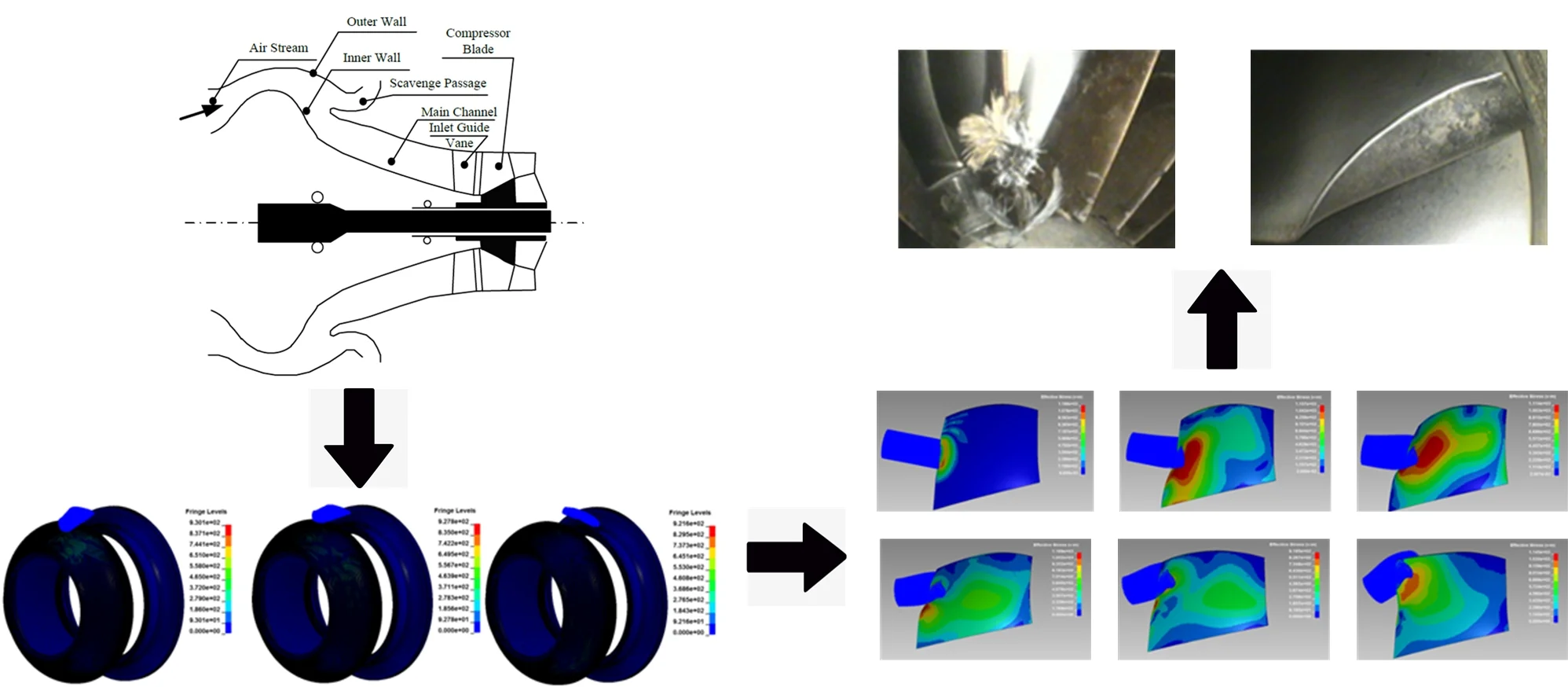
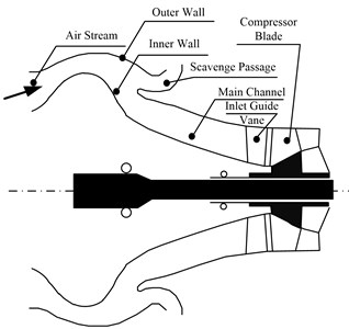
The intake of the turbo-shaft engine is shown in Fig. 1. When a bird is sucked into the engine, it would first hit the hump-shaped inner wall of the particle separator, passes through the inlet channel, the inlet guide vane, and then hit the first-stage blade of the compressor.
Fig. 1A schematic diagram of the intake of the turbo-shaft engine
Based on GJB242A-2018 [2] and literature [8], bird bodies of two different specifications, body A and B, are established with 2:1 length to diameter ratio. Body A, the larger one, is used to impact the inner wall of the particle separator and body B to impact the first-stage blades of the compressor. According to previous experimental experiences, the bird body would break and the larger fragments would be stuck by the inlet guide vane after hitting the inner wall of the particle separator at high speed. Therefore, the mass and volume of body B are one fourth of those of bird body A.
The bird body adopts the MAT10 (MAT_ELASTIC_PLASTIC_HYDRO_) constitutive model in LS-DYNA, and the polynomial state equation [13] is introduced to improve the accuracy. The finite element model of the bird body is shown in Fig. 2. The parameters of the bird body are shown in Table 1 and coefficients of the state equations are shown in Table 2.
Fig. 2Finite element model of bird body

a) Body A
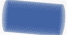
b) Body B
Table 1Parameters of the bird model
Bird | Weight / g | Length / mm | Diameter / mm | Particle number | Density/ kg/m3 | Shear modulus / MPa | / MPa | Cutout pressure | Failure strain |
A | 100 | 80 | 40 | 101120 | 950 | 2000 | 0.001 | 0 | 1.25 |
B | 25 | 32 | 16 | 25984 |
Fig. 3Finite element model of particle separator and blade
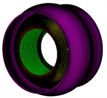
a) Particle separator
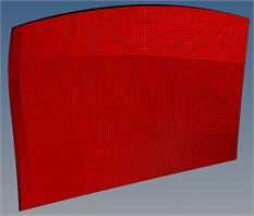
b) Compressor blade
Both the particle separator and the compressor blade are modeled with Solid185. FEM model of the particle separator constitutes of 865,080 elements and 1,107,360 nodes while 82,225 elements and 97,328 nodes for the compressor blade. The finite element models are shown in Fig. 3.
Table 2Parameters of the state equations
Parameters | C0 | C1 | C2 | C3 | C4 | C5 | C6 |
Coefficients | 0 | 5.00E7 | 4.06E9 | 3.03E9 | 0 | 0 | –25 |
3. Numerical results
3.1. Body A collision
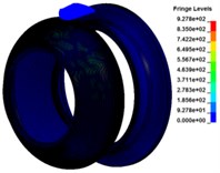
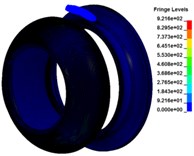
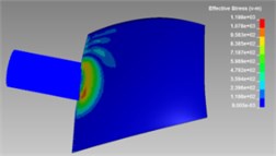
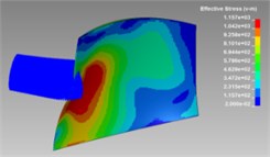
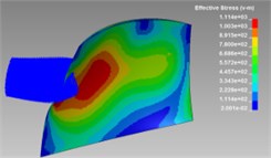
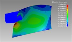
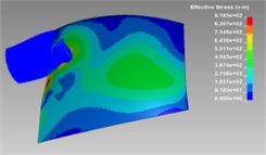
The impact process of body A is simulated with 180 km/h initial speed. Stress contours during impact process are shown in Fig. 4 and the velocity variation curve is shown in Fig. 5-7.
It can be seen from Fig. 4 that body A would quickly bounces upward along the wall and deforms greatly (the actual bird body would generally be broken) after collision with inner wall of the particle separator. Then it collides with the outer wall of the particle separator and the process repeated several times, during which body A might enter the cleaning channel and thus protecting the compressor.
Fig. 4Stress contours during impact process for body A
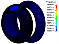
a)0.36 ms

b)0.69 ms
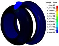
c)1.275 ms
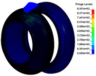
d)1.575 ms
e)2.07 ms
f)2.07 ms
Fig. 5Velocity in X direction
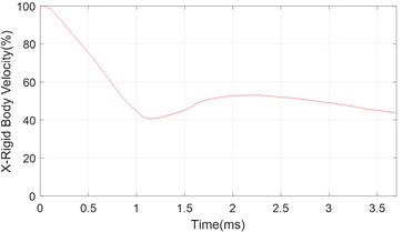
Fig. 6Velocity in Y direction
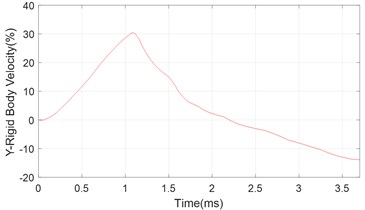
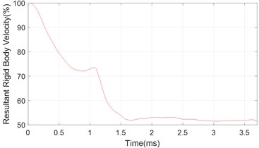
After multiple collisions with the particle separator, obvious speed attenuation in -direction can be observed, Fig. 5, while speed in -direction varies little comparing with initial state, Fig. 6. Also, the remaining speed of body A is approximately 52 % of the initial speed, Fig. 7. Figs. 5-7 provide basis for the subsequent analysis of body B impacting the first-stage blade of the compressor.
Fig. 7Absolute velocity variation
3.2. Body B collision
Based on results of Section 3.1, body A undergoes a large deformation (broken) after collision with the particle separator, and the speed would decay to approximately 52 % of the initial state. Therefore, to simulate the fragments of body A, the weight of body B is one quarter of body A, and the initial speed is set to half of body A, i.e. 90 km/h.
Also, field survey shows that 90 % of the damage to the compressor blades locate at approximately 60 % of the blade height [14]. Thus, it was assumed that body B would hit the blade at 60 % of the blade height. The stress contour during the collision process is shown in Fig. 8, and the compressor blade deformation after the impact is shown in Fig. 9.
Fig. 8Stress contours during impact process for body B
a)0.03 ms
b)0.15 ms
c)0.24 ms
d)0.45 ms
e)0.63 ms
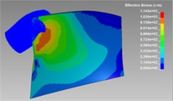
f)0.81 ms
It can be seen from Fig. 8 that body B would be further ripped by the leading edge of the blade and then sliding to the tip. Also, a maximum deformation of 7.6 mm was observed on the blade, Fig. 9(a). The blade tip, which collided with the ripped bird body, deformed approximately 10 mm, Fig. 9(b).
Fig. 9Deformation during impact process
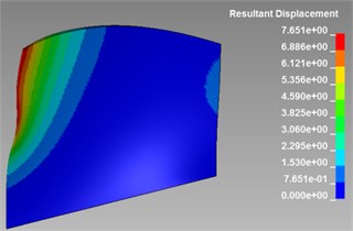
a) Largest deformation of the impact point
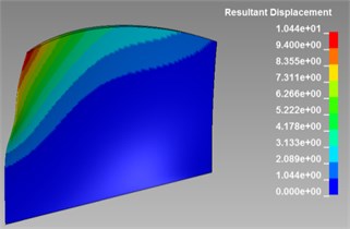
b) Largest deformation of the blade tip
4. Experimental results
In order to validate the numerical simulation results in section 3, bird ingestion experiments was carried out on a certain turbo-shaft engine with three different birds. The schematic diagram of the engine is shown in Fig. 1 and parameters of the birds are listed in Table 3. All the birds were artificially domesticated and purchased from the local farmer’s market. The distributor has the legal license to kill the birds with electric shock. All the birds were killed by electric shock before the experiments.
Table 3Parameters of the state equations
No. | Count | Weight / g | Velocity / km/h |
1 | 2 | 94.7 | 180 |
2 | 2 | 101.4 | 180 |
3 | 2 | 99.5 | 180 |
For the first experiment, the bird was stuck at the entrance of the particle outlet and failed entering main channel of the engine, Fig. 10, which was consistent with the simulation results in Fig. 4. In the second experiment, the bird body was only slightly broken and it was found that most of the bird body was stuck between the two blades of the inlet guide vane, as shown in Fig. 11(a). After the bird body was removed, no obvious structural deformation was found on the inlet guide vane, as shown in Fig. 11(b).
Fig. 10The first bird ingestion experiment
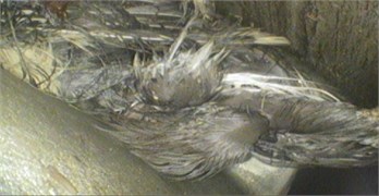
Fig. 11The second bird ingestion experiment
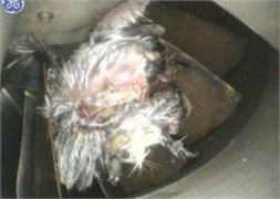
a) Bird stuck by the inlet guide vanes
b) Inlet guide vanes after bird cleaned
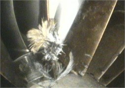
Fig. 12The third bird ingestion experiment
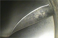
The third and the most successful one, the bird was sucked into main channel, passing through the inlet guide vane and colliding with the first stage compressor blade. A 12×5 mm2 curling deformation was observed, Fig. 12, which are basically consistent with the simulation results. However, there are some differences between experimental and numerical results in the size of the pits caused by the impact. The main reason is that the speed and size of the bumped and ripped bird body are different from the initial setting used in numerical simulation.
5. Conclusions
Two bird models were established with the SPH method to simulate bird impacting on the inner wall of the particle separator and the first-stage blade of the compressor, respectively. Bird ingestion experiments were carried out to validate results of the numerical simulation. The experimental results show great consistency with the numerical results. It can be concluded that:
1) After hitting the inner wall of the particle separator, the bird body would rapidly rebound upward along the wall and very large deformation can be observed in simulation. The real bird would be ripped into pieces during this process and then might enter scavenge passage, thus protecting the core of the engine.
2) The speed of the bird body can be greatly attenuated after hitting the particle separator for several times. The remaining speed is about 52 % of the initial one.
3) The larger the bird body is, the more likely it would be jammed by the inlet guide vanes, which would protect the core of the engine.
4) The smaller bird body would probably pass through the inlet guide vane and collide with the first-stage compressor blade to cause serious curling and deformation of the leading edge of the blade.
References
-
Zhu Yan, Air Force Auxiliary Airport bird identification system development. (in Chinese), Nanjing, 2009.
-
Ma Li, Jiang Jiayu, Et, and Al, “Research on Bird Impact of Aeroengine First Stage Fan,” (in Chinese), Aeroengine, Vol. 40, No. 2, pp. 65–68, 2014.
-
R. A. Dolbeer and S. E. Wright, “Wildlife Strikes to Civil Aircraft in the United States, 1990-2007,” United States, Department of Transportation, Federal Aviation Administration, Tech Report, Jun. 2008.
-
N. Lakshman, R. Raj, and Y. Mukkamala, “Bird strike analysis of jet engine fan blade,” in 2014 IEEE Aerospace Conference, pp. 1–7, Mar. 2014, https://doi.org/10.1109/aero.2014.6836249
-
Li Yulong and Shi Xiaopeng, “Investigation of the present status of research on bird impacting on commercial airplanes,” (in Chinese), Acta Aeronautica et Astronautica Sinica, Vol. 33, No. 2, pp. 189–198, 2012.
-
Chen Wei, Gao Deping, and Yin Jing, “Research on bird-impact on blade of aero-engine,” (in Chinese), Gas Turbine Experiment and Research, Vol. 11, No. 4, pp. 34–39, 1998.
-
Zhang Yongkang and Li Yulong, “Numerical study on bird mechanical model,” (in Chinese), Computer Simulation, Vol. 28, No. 9, pp. 67–70, 2011.
-
Liu Jun, Li Yulong, and Et. Al, “Numerical simulation study of bird-impact on a blade using SPH method,” (in Chinese), Journal of vibration and shock, Vol. 27, No. 9, pp. 90–93, 2008.
-
Wang et al., “A contact-impact coupled simulation for failure of aircraft windshield against bird strike,” Journal of Vibration and Shock, Vol. 31, No. 2, pp. 687–695, 2008.
-
U. A. Dar, W. Zhang, and Y. Xu, “FE Analysis of Dynamic Response of Aircraft Windshield against Bird Impact,” International Journal of Aerospace Engineering, Vol. 2013, pp. 1–12, 2013, https://doi.org/10.1155/2013/171768
-
G. R. Liu and M. B. Liu, Smoothed Particle Hydrodynamics: A Meshfree Particle Method. WORLD SCIENTIFIC, 2003, https://doi.org/10.1142/5340
-
“Commission for Science, Technology and Industry for National Defense, GJB241A-2010,” The General Reserve Department of PLA, Beijing, China, 2010.
-
Wen Yingjuan, Parametrization and Validity Analysis on the Response of Flat Blades due to Bird. (in Chinese), Nanjing, China, 2006.
-
R. Hedayati and S. Ziaei-Rad, “A new bird model and the effect of bird geometry in impacts from various orientations,” Aerospace Science and Technology, Vol. 28, No. 1, pp. 9–20, Jul. 2013, https://doi.org/10.1016/j.ast.2012.09.002
About this article

