Abstract
During the actual operation of the full-face tunnel boring machine (TBM), the vibration of the mainframe system is very strong, leading to the failure of key parts. Therefore, the vibration characteristics of TBM Cutter head under the maximum thrust condition are analyzed by ANSYS finite element software, and the effects of Cutter head panel thickness, Cutter head baseplate thickness, and support plate thickness on Cutter head vibration are analyzed. Subsequently, the optimal solution of the system is obtained by analyzing the data with orthogonal tests. It provides a reference for vibration reduction and parameter matching of Cutter head.
1. Introduction
TBM roadheader is widely used in various types of hard rock tunnel construction. A cutter head is a vital digging component of a roadheader. Moreover, the efficiency and safety of construction are directly influenced by the effectiveness of the roadheader work [1, 2]. By completing a dynamic model of the shield machine, Xian Hong Li et al. and Zhang K et al. analyzed some key parameters such as rotation and torque inside the system and found the relevant key issues [3, 4]. The vibration model of TBM Cutter head system was constructed by Jing Yang. Based on numerous scientific researches, the relationship between relevant digging performance and dynamic characteristics is analyzed in conjunction with the actual working conditions [5]. Ling J and other researchers have launched a prediction initiative for excavation parameters of roadheader under typical mixed working conditions [6] Tianmin Guan et al. analyzed the force characteristics of Cutter head and tool separately after the establishment and calculation of Cutter head Finite element model [7]. In the construction of Cutter head model of shield structure by Yi-Min Xia et al. the Cutter head modal analysis was realized by finite element method [8]. Zhao Zhenwei et al. implemented the analysis of the mechanical properties of Cutter head of different structural types and found the method to improve the overall stiffness of hard rock cutter [9].
The above-mentioned studies mainly concentrated on the dynamic characteristics and parameter prediction of TBM Cutter head, while the vibration characteristics of Cutter head under different working conditions were less studied. In fact, when TBM Cutter head is dug under complex geological conditions, especially in the case of both rock and soft soil, the Cutter head is prone to vibration and leads to accelerated damage of system components. Therefore, ANSYS software is used to analyze the vibration characteristics of hard rock cutter structure in this paper. In this paper, the vibration characteristics of hard rock cutter structure are analyzed by ANSYS software. This includes analyzing the influence of different parameters to make it have good dynamic and static characteristics and high reliability, improve fatigue life and reduce vibration.
2. TBM cutter head 3D model and load distribution
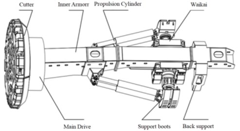
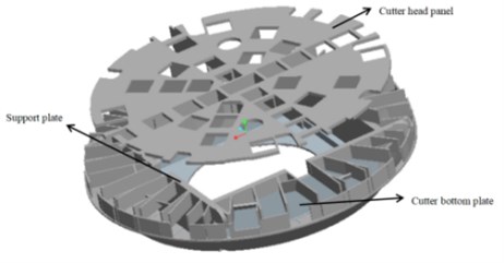
In this paper, the TBM consists of Cutter head, main drive, thruster, Cutter head support device, propulsion cylinder and other parts. The Cutter head diameter selected in this paper is 8416mm, and the material selected is Q345 steel. 3D modeling of the Cutter head as a whole is carried out using PRO/E software, as shown in Fig. 1. Among them, the core working part of the whole machine is TBM Cutter head, and the internal structure and connection relationship of the system are quite complicated. In combination with the harshness of the actual surrounding geological environment of the TBM and the variability of the tunneling parameters, the system is subjected to spatially distributed loads and vibration problems are particularly prominent, leading to abnormal structural failures.
Fig. 1TBM cutter head structure and 3D model
In the research of the load spectrum design process of TBM Cutter head, the typical working conditions of TBM Cutter head are usually defined as four types: (1) the maximum thrust working condition. (2) Maximum overturning moment. (3) Turning correction condition. (4) Escape condition. The equation in the literature can be obtained when the maximum thrust condition [10] Cutter head is subjected to the maximum load and the vibration is most obvious. The maximum thrust condition is used in this paper for loading and axial force 14682 kN, radial force 126 kN, overturning moment 1156 kNm, and torque 5763 kNm.
3. Analysis of vibration characteristics of cutter head
Modal analysis is to solve the vibration characteristics under free vibration, and the main parameters for the solution are the inherent frequency and the modal vibration pattern. A harmonic response analysis is used to solve the structural response of the structure under the action of periodic load and the dynamic characteristics under different frequency loads, which provides theoretical support for subsequent optimization. The calculation of harmonic response analysis is carried out by Modal superposition method with the same boundary constraints This means that the full restraint treatment is made near the lowermost flange of the hard rock cutter, and the axial force, radial force, overturning moment and torque values under the maximum thrust condition are added to the external load for analysis. Depending on the hard rock cutter first six orders of inherent frequency and vibration type, the harmonic response is analyzed in the frequency range of 66-166 Hz [11], and the first six inherent orders of frequency are included, and the response is calculated in 100 sub-steps. And define the axis, axis and axis of cuterhead as shown in Fig. 2.
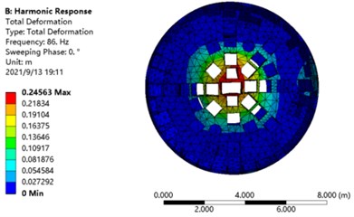
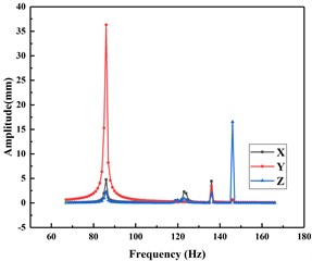
In Fig. 3, the results of the harmonic response analysis of the TBM Cutter head in the , , directions and the maximum deformation at 86 Hz are shown. From the figure, it can be seen that the resonance position mainly occurs at 86 Hz and 146 Hz. At 86 Hz, the vibration in the direction is the most obvious, and the vibration displacement reaches the maximum. At 146 Hz, the displacement in direction reaches the maximum. Therefore, the resonance is easy to occur at 86 Hz and 146 Hz. For the purpose of improving the service life of TBM Cutter head, the vibration displacement should be reduced as much as possible at the resonance.
Fig. 2Cutter head direction definition diagram
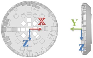
Fig. 3Harmonic response vibration analysis diagram
a)
b)
4. Parameter influence analysis of cutter head vibration response
4.1. Orthogonal design
For ensuring the reasonableness and accuracy of the test results, the selected parameters need to be noted for the effects of parameter variations on the vibration characteristics of the finite element simulation model. The three-factor, three-level orthogonal test scheme was adopted, and the orthogonal experimental factors were prepared Table 1.
Table 1Orthogonal test factor table
Level | Factors | ||
Cutter head panel (mm) | Cutter head baseplate (mm) | Support plate (mm) | |
1 | 90 | 50 | 180 |
2 | 120 | 75 | 210 |
3 | 150 | 100 | 240 |
Table 2Orthogonal test design table
Test number | Cutter head panel (mm) | Cutter head baseplate (mm) | Support plate (mm) | Empty column |
1 | 90 | 50 | 180 | 2 |
2 | 120 | 50 | 210 | 1 |
3 | 150 | 50 | 240 | 3 |
4 | 90 | 75 | 240 | 1 |
5 | 120 | 75 | 180 | 3 |
6 | 150 | 75 | 210 | 2 |
7 | 90 | 100 | 210 | 3 |
8 | 120 | 100 | 240 | 2 |
9 | 150 | 100 | 180 | 1 |
In this paper, a 3-factor, 3-level test is selected. Therefore, a -type orthogonal table is to be used, and because there are 3 factors and the interaction is not considered for the time being, a table with 3 is to be selected, while is an orthogonal table that satisfies the condition, so an orthogonal table is chosen to arrange the experiment. The completed table design is shown in Table 2.
In this orthogonal experiment design, the vibration amplitude of axis is taken as a reference, and the primary and secondary difference and strength of the conditions affected by the parameters are determined as the goal.
Fig. 4Schematic diagram of selection of cutter head factors
5. Analysis of the influence of cutter head vibration response parameters
According to Table 2, the simulation of Finite element model is carried out by orthogonal test, and the Vibration response result analysis table 3 is made by the average amplitude of axis in the Table 3 Vibration response results under all 86 Hz frequency loads.
Table 3Vibration response analysis table (Y axis)
Scheme number | Factor | Test results axis vibration (mm) | |||
Cutter head panel (mm) | Cutter head baseplate (mm) | Support plate (mm) | Empty column | ||
1 | 90 | 50 | 180 | 1 | 36.31 |
2 | 120 | 50 | 210 | 2 | 3.6892 |
3 | 150 | 50 | 240 | 3 | 5.3467 |
4 | 90 | 75 | 240 | 2 | 2.6484 |
5 | 120 | 75 | 180 | 3 | 2.4374 |
6 | 150 | 75 | 210 | 1 | 14.718 |
7 | 90 | 100 | 210 | 3 | 2.0554 |
8 | 120 | 100 | 240 | 1 | 10.932 |
9 | 150 | 100 | 180 | 2 | 1.3148 |
41.0138 | 45.3459 | 40.0622 | 61.96 | ||
17.0586 | 19.8038 | 20.4626 | 7.6524 | ||
21.3795 | 14.3022 | 19.9271 | 9.8395 | ||
13.6713 | 15.1153 | 13.35407 | 20.6533 | ||
5.6862 | 6.60127 | 6.82087 | 2.5508 | ||
7.1265 | 4.7674 | 6.309 | 3.27983 | ||
7.9851 | 10.3479 | 7.045 | 18.1025 | ||
Primary factor → secondary factor | Cutter head baseplate Cutter head panel Support plate | ||||
Excellent scheme | Panel 3 base plate3 Support plate 1 | ||||
The influence of -axis direction on Cutter head vibration is the greatest, and the extreme difference is , so the influence of three factors on the vibration is Cutter head baseplate, Cutter head panel, and Support plate from the largest to the smallest. The optimum solution for Cutter head is Cutter head base plate100 mm, Cutter head panel 150 mm and Support plate1 80 mm under the maximum thrust condition, and the vibration in -axis direction is reduced from 36.31 mm to 1.3148 mm under the load frequency of 86 Hz.
6. Conclusions
The vibration model of Cutter head is established based on ANSYS finite element simulation platform, and through the -axis translational vibration of Cutter head -axis under the maximum thrust condition, the following conclusions can be drawn.
1) The vibration of Cutter head is maximum at 86 Hz resonance point under the maximum thrust condition, and the vibration mainly occurs in -axis direction.
2) The orthogonal test is applied to analyze the effect of Cutter head baseplate, Cutter head panel and support plate on the -axis vibration of Cutter head. The optimal solution is obtained by intuitive analysis: Cutter head baseplate 100 mm, Cutter head panel 150 mm, Support plate 180 mm.
3) The thickness of Cutter head baseplate has the greatest effect on Cutter head vibration, and the thickness of Cutter head panel and Support plate has about the same effect.
References
-
J. Wei, Q. Sun, W. Sun, X. Ding, W. Tu, and Q. Wang, “Load-sharing characteristic of multiple pinions driving in tunneling boring machine,” Chinese Journal of Mechanical Engineering, Vol. 26, No. 3, pp. 532–540, May 2013, https://doi.org/10.3901/cjme.2013.03.532
-
J. Huo, D. Zhu, N. Hou, W. Sun, and J. Dong, “Application of a small-timescale fatigue, crack-growth model to the plane stress/strain transition in predicting the lifetime of a tunnel-boring-machine cutter head,” Engineering Failure Analysis, Vol. 71, pp. 11–30, Jan. 2017, https://doi.org/10.1016/j.engfailanal.2016.11.002
-
X. H. Li, H. B. Yu, M. Z. Yuan, J. Wang, and Y. Yin, “Dynamic modeling and analysis of shield TBM cutterhead driving system,” Journal of Dynamic Systems, Measurement, and Control, Vol. 132, No. 4, pp. 1–14, Jul. 2010, https://doi.org/10.1115/1.4000818
-
K. Zhang, H. Yu, Z. Liu, and X. Lai, “Dynamic characteristic analysis of TBM tunnelling in mixed-face conditions,” Simulation Modelling Practice and Theory, Vol. 18, No. 7, pp. 1019–1031, Aug. 2010, https://doi.org/10.1016/j.simpat.2010.03.005
-
Yang J., “Vibration characteristics analysis of TBM cutter head system and research on tunneling field test,” (in Chinese), Dalian University of Technology, 2014.
-
J. Ling, W. Sun, J. Huo, and L. Guo, “Study of TBM cutterhead fatigue crack propagation life based on multi-degree of freedom coupling system dynamics,” Computers and Industrial Engineering, Vol. 83, pp. 1–14, May 2015, https://doi.org/10.1016/j.cie.2015.01.026
-
Guan T. M. et al., “Finite element analysis of shield cutter head in sand and gravel stratum,” (in Chinese), Journal of Dalian Jiaotong University, Vol. 36, pp. 43–46, 2015.
-
Xia Y. M. et al., “Finite element analysis of a certain type of earth pressure balance shield cutterhead,” (in Chinese), Journal of Zhengzhou University (Engineering Edition), Vol. 3, pp. 73–77, 2009.
-
Zhao Z. W. et al., “Comparative analysis of static mechanical properties of TBM cutterheads with different geometric structures,” (in Chinese), Tunnel Construction, Vol. 36, No. 1, pp. 102–107, 2016.
-
Ling J. X., “Vibration analysis and life prediction of TBM cutterhead under spatially distributed loads,” (in Chinese), Dalian University of Technology, 2017.
-
Zhang J. S., Ji Y. X., Zhang Y. F., Wang W., and Liu J., “Modal analysis and research of roadheader cutterhead based on ANSYS,” (in Chinese), Machine Design, Vol. 33, No. 9, pp. 101–104, 2016.
About this article

