Abstract
In this study, a three-dimensional numerical model of an ejector is established, which is based on a 40 W power proton exchange membrane fuel cell (PEMFC) system. Computational Fluid Dynamics (CFD) technique is used to analyze the ejector in low power condition. The effects of two key structural parameters (distance from the mixing chamber to the nozzle and the mixing chamber diameter) on the ejector performance at different currents are investigated. It is found that ejector entrainment ratio changes slightly with the distance from mixing chamber to nozzle. The ejector entrainment ratio increases first and then decreases with the mixing chamber diameter. Moreover, with the increase of mixing chamber diameter, the turbulent kinetic energy and turbulent dissipation rate decrease obviously.
Highlights
- The effects of two key structural parameters (distance from the mixing chamber to the nozzle and the mixing chamber diameter) on the ejector performance at different currents are investigated.
- Optimized ejector performance improved 14.53 %.
- With the increase of mixing chamber diameter, the turbulent kinetic energy and turbulent dissipation rate decrease obviously.
1. Introduction
PEMFC offers excellent performance in terms of efficiency, power density, emissions and low temperature startability. It is considered to be the ideal replacement for the conventional automotive internal combustion engine. To ensure the stable operation of the fuel cell [1], excess hydrogen is supplied to the cell anode, so the anode hydrogen circulation system is essential for the proper operation of the fuel cell system. Both mechanical circulation pumps and ejectors can be used in hydrogen circulation systems. Compared with mechanical pumps, the ejector has the advantages of high relative system efficiency (owing to the absence of parasitic power), small size, simple structure and design, and low maintenance costs (owing to the absence of movable parts), which have aroused extensive research interest [2].
Keenan et al. [3] proposed the design theory of the inducer by establishing the conservation equations of mass, momentum and energy in one dimension, which pioneered the theoretical calculation of the inducer. Later, Sokolov et al. [4] proposed design formulas and empirical coefficients for the theoretical calculation of the inducer through experiments, which are still widely used. However, only a limited number of studies have been conducted on ejectors for anode hydrogen recirculation in PEMFC systems. There is no good solution to the problem of the narrow operating range of the inductor of the PEMFC anode hydrogen circulation system.
In this study, the objective is to establish a 3D numerical model of an ejector for the anode recirculation in PEMFC system, and to investigate the effect of geometrical parameters on the performance of the ejector under low power conditions. An optimization of the ejector design is also carried out.
2. Ejector
2.1. Structures
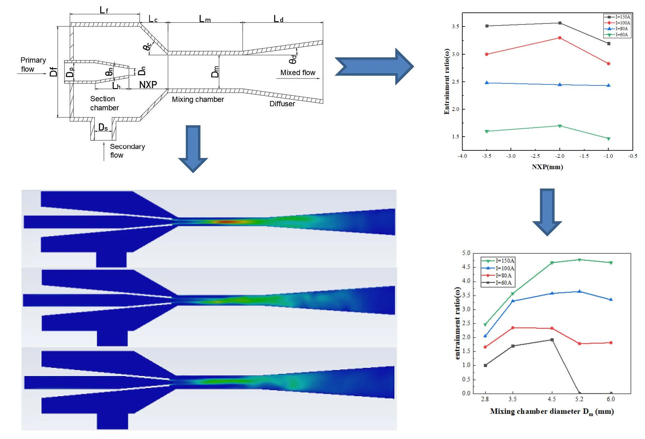
The structure chart of the ejector is illustrated in Fig. 1. It consists of five parts, a primary flow nozzle (working fluid inlet), secondary flow tube (entrained fluid inlet), suction chamber, mixing chamber, and diffuser.
When the ejector is working, the primary flow is accelerated through the nozzle, and a low pressure area is formed at the nozzle exit. In the meantime, the secondary flow is injected into the ejector. The large pressure difference between the low pressure area and the secondary flow will draws the secondary fluid into the mixing chamber. The two fluids are mixed in the mixing chamber, and the pressure of mixed fluid continues to increase in the diffuser chamber. The mixed fluid is ejected from the diffuser into the hydrogen inlet of the stack to achieve the next chemical reaction [5].
Fig. 1Structure chart of the ejector
2.2. Design
The performance of the ejector is evaluated by entrainment ratio , which is the ratio between the mass flows rate of the secondary inlet to the primary inlet. It is shown as:
where is the mass flow rate of the secondary flow, is the primary inlet mass flow rate which is calculated by:
where is the cell number of the stack, is Faraday constant (equals to 96485), is the operating current, and is the molar weight of hydrogen.
Besides, many important geometric parameters in the ejector are determined by empirical equation. For example, the most important parameter is the nozzle throat diameter , which is calculated from the isentropic flow laws and energy balance [6]:
where (equals to /4) is the nozzle throat area, (equals to 1.4) is the isentropic coefficient, is specific heat ratio of the gas in the primary flow and (equals to 8.3145) is gas constant.
The geometric parameters of the designed ejector are provided in Table 1, and some of them are determined on previous research [6], including the mixing chamber diameter () and length (), the distance from the mixing chamber to the nozzle (NXP), and diffusion length () and diffusion angle (). Besides, Elham [7] simulations showed that there are only two key parameters which play an important role in the performance of an ejector. Moreover, the recommended size of is 3 to 6 times .
Table 1Basic size
Parameters | Values | Parameters | Values |
Nozzle throat diameter (mm) | 1.4 | Mixing chamber diameter (mm) | 3.5 |
Nozzle length (mm) | 16 | Mixing chamber length (mm) | 28 |
Nozzle convergence angle (°) | 10 | Mixing tube convergence angle (°) | 30 |
Nozzle extension diameter (mm) | 4.2 | Secondary flow tube inlet diameter (mm) | 10 |
Diffuser angle (°) | 4 | Suction chamber length (mm) | 30 |
Diffuser length (mm) | 43 | Suction chamber diameter (mm) | 20 |
NXP (mm) | –2 |
3. Numerical modeling and simulation
3.1. Governing equations
In order to establish an effective numerical model of the ejector for PEMFC system that can be calculated by CFD simulation. The main assumptions of the PEMFC system are as follows:
1) The PEMFC system works in a steady state.
2) The primary gas is treated as an ideal gas so that satisfies the equation of ideal gas.
3) The secondary flow is wet hydrogen with a relative humidity of 80 %, and the water inside is in the gas phase.
4) Water vapor condensation and gravity of the gas are neglected.
5) The inner wall of the ejector is treated to be adiabatic.
Based on the above assumptions, the equations used in the numerical calculation of ejectors are as follows:
The continuity equation:
The momentum conservation equations:
With the ideal gas relationship:
The energy equation:
Species transport equation:
where is the density, is the velocity, is the stress tensor, is the is unit tensor, is the specific gas constant, is the total energy, is the thermal conductivity, is the enthalpy, , , , , , are diffusion flux, mass fraction, mass diffusion coefficient, thermal diffusion coefficient of species q, the turbulent viscosity, and the turbulent Schmidt number ,respectively.
In addition, based on the previous analyses [4, 6, 7], the RNG - turbulent model seems to be the most appropriate turbulent model for the ejector simulation. The RNG - turbulent model is therefore used in the present simulation.
3.2. Boundary conditions
The primary flow of the ejector is pure hydrogen, and its mass flow rate is a constant under a steady PEMFC system operating current. The ejector secondary flow chamber inlet pressure and diffuser outlet pressure are associated with the PEMFC stack inlet pressure and outlet pressure, respectively. As a result, the primary flow inlet boundary condition is set to a constant mass flow boundary. The secondary flow is a mixture of hydrogen and water vapor. The secondary flow inlet and the mixture outlet are set as pressure inlet and pressure outlet boundaries respectively. All other surfaces of the ejector are configured as adiabatic walls. The detailed boundary parameters were presented in Table 2.
Table 2Operating parameters of the ejector in 150 A conditions
Primary flow mass flow rate | Primary flow temperature | Secondary flow pressure | Secondary flow temperature | Mass fraction of water vapor in secondary flow | Ejector exit pressure |
0.0006 kg·s-1 | 298 K | 2.0 bar | 353 K | 0.57 | 2.3bar |
3.3. Numerical technique
The geometry was created using the software SOLIDWORKS 2022. The commercial software Workbench 2020 is used for mesh generation and governing equation solving. The RNG - turbulent model is used to simulate the complex fluid flow inside the ejector and the species model is used to solve the gas species transport. The SIMPLEC method is applied to solve the pressure field. The momentum, species transport and turbulent kinetic energy are discretized using the second-order upwind scheme, and the corresponding sub-relaxation factors are set. Initially, the gas velocity and the gauge pressure are both 0 in the fluid domain. For each simulation case, the convergence accuracy of residual is set to 10-5.
3.4. Mesh independency verification
To improve accuracy, hexahedral mesh is selected. The mesh near the ejector wall was refined to capture fluid flow near the wall, and the mesh of nozzle outlet was refined to improve the accuracy of fluid flow simulation. In order to ensure the accuracy of the calculated results, not only the quality of the mesh is strictly required, but also the mesh independence of the established injector model is verified. In order to prove the mesh independency, three different sets of mesh were generated and analyzed from the coarse level to exquisite level (“low” mesh:503710 elements, “medium” mesh: 864497 elements and “fine” mesh:1336019 elements). The calculation results are almost the same and the max relative error is below 3 %. After comprehensive consideration, this paper finally selected the mesh level with 864497 elements for simulation experiments.
3.5. Model validation
In order to verify the reliability of the model, the simulation results are compared with the experimental data in the literature. The geometric parameters, boundary conditions and working fluid of the model are consistent with experimental data in literature [1], [10]. Compared with the entrainment ratio of primary flow inlet pressure ranging from 4.5 to 6 bar, the relative error of the entrainment ratio between simulation results and experimental data is less than 5 %, indicating that the model has relatively high reliability. The deviation between simulation and experiment may result from the experimental error and machining error of the ejector.
4. Results and analysis
4.1. Distance from mixing chamber to nozzle
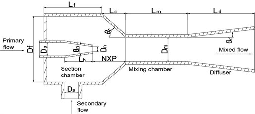
The distance from the mixing chamber to the nozzle is called NXP. The value of NXP is positive when the nozzle outlet is located in the mixing chamber indoor part, otherwise it is negative. The influence of NXP on the performance of the ejector under four different currents is shown in Fig. 2. As seen, for each set current value, the entrainment ratio has a peak at NXP = –2. From the perspective of energy, when the distance is smaller, the friction loss along the distance is smaller so that the entrainment ratio is higher. However, the smaller distance also leads to the lack of sufficient distance to entrap secondary fluid, so the entrainment ratio is not high. On the contrary, When the nozzle is far away from the mixing chamber, the larger wall pressure leads to increased momentum loss, so the mixing fluid cannot enter the mixing chamber in time and the entrainment ratio decreases gradually. To ensure stable operation of the ejector at low power, NXP = –2 mm is chosen.
Fig. 2Variation of ω versus NXP at different currents
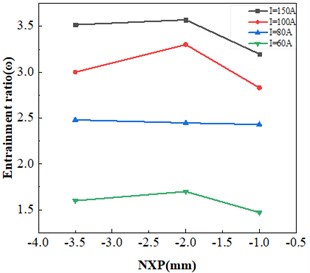
Fig. 3Variation of ω versus Dm at different currents
4.2. Mixing chamber diameter
The mixing chamber diameter is another important factor in the performance of the ejector. The optimized NXP (–2 mm) was taken, and the initial design values of other structural parameters were kept unchanged. Therefore, only the mixing chamber diameter was changed. The influence of mixing chamber diameter on entrainment ratio under four different current conditions is shown in FIG. 3. It can be seen that the maximum entrainment ratio was obtained for 150 A, 5.2, and 4.78, and when the diameter of mixing chamber deviates from the optimal value under the same working condition, the entrainment ratio decreases sharply.
However, when 5.2 mm, the ejector lose efficacy at 60 A. The higher optimal at high load conditions is due to the higher inlet pressure of the primary flow at this time. Therefore, there is sufficient pressure potential energy to accelerate the secondary fluid.
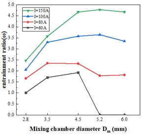
Fig. 4 shows the distribution of turbulent kinetic energy in the ejector with different mixing chamber diameters. As seen, the turbulent core region is formed in the mixing tube, where the turbulent kinetic energy of the fluid reaches the maximum and dissipates quickly. It promotes mixing between primary and secondary fluids. With the increase of mixing chamber diameter, the turbulent kinetic energy and turbulent dissipation rate decrease obviously. In order to ensure full mixing of fluid in mixing chamber, the effect of mixing chamber diameter on turbulent kinetic energy should be fully considered. In addition, when the diameter of mixing chamber is small, the flow area of gas in mixing chamber is small, which will greatly limit the performance of the ejector. Finally, in order to cover the higher range of the current, 4.5 mm was chosen.
Fig. 4Contour of turbulence kinetic energy
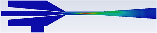
a)2.8 mm
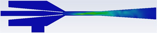
b)3.5 mm
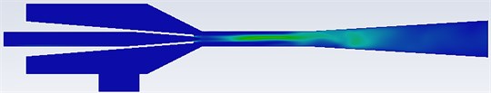
c)4.5 mm

d) Scale (m2/s2)
5. Conclusions
In this study, based on a 40 W power PEMFC system, a 3D ejector numerical model is designed using CFD technique. The working performance of the ejector under low load conditions is studied to enlarge the working range of the ejector, and some main geometric parameters are optimized. The ejector entrainment ratio has a slight influence with the distance from mixing chamber to nozzle. The ejector entrainment ratio increases first and then decreases with the mixing chamber diameter. The maximum ejector entrainment ratio exists at medium the distance from mixing chamber to nozzle and the mixing chamber diameter. When the mixing chamber diameter () is greater than 6 times nozzle throat diameter (), the ejector is completely inoperative. Moreover, the increase of mixing chamber diameter will lead to the decrease of turbulent kinetic energy, which is not conducive to fluid mixing. Finally, optimized ejector performance improved 14.53 %.
References
-
Y. Yin, M. Fan, K. Jiao, Q. Du, and Y. Qin, “Numerical investigation of an ejector for anode recirculation in proton exchange membrane fuel cell system,” Energy Conversion and Management, Vol. 126, pp. 1106–1117, Oct. 2016, https://doi.org/10.1016/j.enconman.2016.09.024
-
M. Dadvar and E. Afshari, “Analysis of design parameters in anodic recirculation system based on ejector technology for PEM fuel cells: A new approach in designing,” International Journal of Hydrogen Energy, Vol. 39, No. 23, pp. 12061–12073, Aug. 2014, https://doi.org/10.1016/j.ijhydene.2014.06.046
-
J. H. Keenan, E. P. Neumann, and F. Lustwerk, “An investigation of ejector design by analysis and experiment,” (in Chinese), Journal of Applied Mechanics, Vol. 17, No. 3, pp. 299–309, Sep. 1950, https://doi.org/10.1115/1.4010131
-
E. Sokolov and H. M. Jin Geer, Ejector. (in Chinese), Beijing: Science Press, 1977.
-
X. Zhang, L. Wang, H. Zhang, and L. Jia, “Optimization of ejector structure for the PEMFC hydrogen recirculation system,” in 2020 Chinese Automation Congress (CAC), Nov. 2020, https://doi.org/10.1109/cac51589.2020.9327006
-
Y. Zhu, W. Cai, C. Wen, and Y. Li, “Fuel ejector design and simulation model for anodic recirculation SOFC system,” Journal of Power Sources, Vol. 173, No. 1, pp. 437–449, Nov. 2007, https://doi.org/10.1016/j.jpowsour.2007.08.036
-
E. Hosseinzadeh, M. Rokni, M. Jabbari, and H. Mortensen, “Numerical analysis of transport phenomena for designing of ejector in PEM forklift system,” International Journal of Hydrogen Energy, Vol. 39, No. 12, pp. 6664–6674, Apr. 2014, https://doi.org/10.1016/j.ijhydene.2014.02.061
-
Z. Du, Q. Liu, X. Wang, and L. Wang, “Performance investigation on a coaxial-nozzle ejector for PEMFC hydrogen recirculation system,” International Journal of Hydrogen Energy, Vol. 46, No. 76, pp. 38026–38039, Nov. 2021, https://doi.org/10.1016/j.ijhydene.2021.09.048
-
Y. Zhu, W. Cai, C. Wen, and Y. Li, “Numerical investigation of geometry parameters for design of high performance ejectors,” Applied Thermal Engineering, Vol. 29, No. 5-6, pp. 898–905, Apr. 2009, https://doi.org/10.1016/j.applthermaleng.2008.04.025
About this article

